Direct Numerical Simulation (DNS) and High-Fidelity Large-Eddy Simulation (LES) for Improved Prediction of In-Cylinder Flow and Combustion Processes
←
→
Page content transcription
If your browser does not render page correctly, please read the page content below
Direct Numerical Simulation (DNS) and High-Fidelity Large-Eddy Simulation
(LES) for Improved Prediction of In-Cylinder Flow and Combustion Processes
Muhsin Ameen, Saumil Patel, Juan Colmenares, Sicong Wu (ANL)
Jackie Chen, Tuan Nguyen, Swapnil Desai (SNL)

2021 DOE Vehicle Technologies Office Annual Merit Review
June 21-25, 2021
Project # ACE146

This work was performed as part of the PACE program. Special This presentation does not contain any proprietary,
acknowledgments to the program managers Gurpreet Singh and confidential, or otherwise restricted information.
Mike Weismiller
Overview
Timeline Barriers
 • PACE started in Q3, FY19 US DRIVE Advanced Combustion and Emission Control
 • PACE will end in FY23 (~25% complete) Roadmap
 • Incomplete understanding of the dynamics of fuel-air mixture
 • Focus and objectives of individual tasks will be continuously preparation
 adjusted • Incomplete understanding of stochastic combustion problems (CCV,
 • Overall PACE work plan discussed in ACE138 misfire, knock)
 US Fiscal years run from October 1 through September 30 PACE Major Outcomes
 • MO1: Current models do not accurately predict knock response to
Budget design changes
 • MO5: Homogeneous and stratified lean/dilute engine efficiency and
 Task Description FY20 FY21
 emissions are not accurately predicted
 • MO8: Understand and improve dilute combustion strategies during
 A.M.05.01
 Spray and Combustion model implementation $350k $340k* cold start and cold operation to reduce emissions
Ameen, ANL

 A.M.05.02
 Partners
 Gridding, validation, and workflow development $350k $300k
Ameen, ANL • PACE is a DOE-funded consortium of 6 National
 S.M.02.01 DNS and modeling of turbulent flame propagation Laboratories working towards a common goal (ACE138)
 $50k $50k
 Chen, SNL & end gas ignition • Specific partners on this work include:
 S.M.02.02 • LLNL on surrogate development and kinetics
 Flame wall interactions $150k $50k
 Chen, SNL • Nek5000 development team at ANL, UIUC
*Listed funding also supported ANL research presented in ACE 143 • PELE development team at LBNL, NREL, ORNL, SNL
 • Additional details on later slides
 2
Relevance

Overall Relevance of PACE:
PACE combines unique experiments with world-class DOE
computing and machine learning expertise to speed
discovery of knowledge, improve engine design tools, and
enable market-competitive powertrain solutions with
potential for best-in-class lifecycle emissions

To achieve PACE objectives, we need:
• Better understanding of CCV under lean/dilute
 operations to develop mitigation strategies
• Accurate knock models under high-load operation
• Accurate flame-wall interaction models under
 lean/dilute and cold-start conditions
• Accurate wall heat transfer models

 Use high-fidelity simulation tools and DOE leadership-class machines to develop accurate submodels
 for combustion, heat transfer, and CCV.
 3
Relevance: Need for more predictive models
 PACE Major Outcome 5 PACE Major Outcome 1
 Dilute Cyclic Variability (M Ameen, owner) High Load Knock (S Som, owner)

 Target Success Baseline
 Target Success Baseline
 COV 10% 100%
 KLSA 1 CAD 3 CAD
 CA10-
 10% 36% 5x faster/5x
 90 CPU cost ---
 more physics
 Simulations performed by Chao Xu
 (ANL)

• CCV is not well-captured. • Current practice is to use Livengood-Wu integrals* to
• Need to tune combustion model parameters from one predict end-gas autoignition which are not sufficiently
 operating condition to the next. accurate.
• Late-stage combustion is not captured well – need for • Need for faster and more accurate end-gas autoignition
 better flame-wall interaction models and wall heat models.
 transfer models.

 *Yue, Z., Xu, C., Som, S. et al., “A Transported Livengood-Wu Integral Model for Knock Prediction in CFD Simulation” ASME ICEF 2020
 4
Milestones

Month/Year Description of Milestone Status Lab
Q2 FY21 Improved wall and heat transfer models Completed ANL
 using DISI DNS
Q4 FY21 Multi-cycle LES Dataset for the motored On Track ANL
 Sandia DISI engine with flow and spray
Q3 FY21 High-fidelity LES of evaporating ECN On Track ANL
 Spray G simulated using Nek5000
Q2 FY21 Improved flame propagation models Delayed to Q4 FY21 ANL
 coupled with PACE ignition model
 implemented into Nek5000 and validated
 using DNS dataset
Q4/FY21 DNS of end gas ignition under boosted On Track SNL
 conditions, flame-wall interaction and
 soot

 5
Approach: Leverage Exascale-ready DOE codes to accomplish PACE objectives

Nek5000 (ANL) S3D (SNL)
High-fidelity DNS/LES of ICE flows DNS of turbulent reactive flows
• Spectral element method (SEM)-based spatial discretization • Solves compressible reacting Navier-Stokes, total energy and
 delivering minimal numerical dispersion and dissipation and species continuity equations
 exponential grid convergence • High-order finite-difference methods
• Body-fitting capabilities for complex geometries, Arbitrary • Detailed reaction kinetics and molecular transport models
 Lagrangian Eulerian (ALE) capabilities to handle moving • Lagrangian particle tracking (tracers, spray, soot)
 boundaries • In situ analytics and visualization
• Capability to model fuel sprays and combustion • Geometry using immersed boundary method
• Mesh generation: supports major 3rd party meshing tools • Refactored for heterogeneous architectures using dynamic task-
• Supported by DOE through ASCR and ECP (Exascale based programming model (Legion)
 Computing Project) funding: ~$7.6M • Sustained funding from ASCR through SciDAC partnerships,
 Exascale Computing Initiative combustion co-design (ExaCT),
 and through ASCR core CS projects

 Approach: Leverage heavy DOE ASCR (Advanced Scientific Computing Research) investments in these
 codes to achieve PACE objectives 6
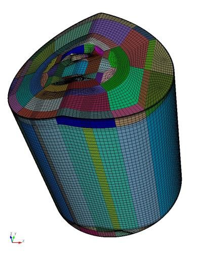
Approach – Multi-Cycle Simulations to Study CCV (ANL)
Objective: Understand relevant in-cylinder flow features that can
affect CCV under lean/dilute conditions
Approach: Combination of open-cycle engineering and wall-
resolved high-fidelity LES of the Sandia DISI engine

 Open-cycle Closed-cycle high-
 engineering LES fidelity LES
 simulations using simulations using
 Converge Nek5000

 CFD Setup for open-cycle Mesh structure for closed-cycle
 Simulation parameters simulations using Converge. Nek5000 simulations
 Nek5000
 Element count 100K - 370K
 DISI Engine Specifications
 Number of grid points 50M - 200M
 Bore 86 mm
 Max. Δ 0.7 mm
 Stroke 95.1 mm
 Min. Δ 0.002 mm
 Connecting Rod Length 166.7 mm
 Converge Compression Ratio 12:1
 Number of grid points 1M – 1.5M RPM 1000
 Max. Δ 1.0 mm

 Min. Δ 0.25 mm
 7
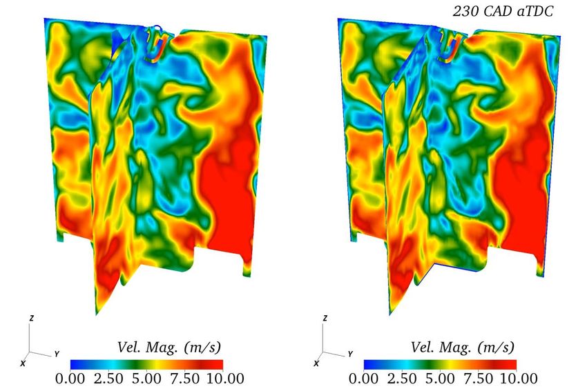
Accomplishment: Demonstrated the need for high-fidelity
simulations to capture CCV
Flow Field Evolution Tumble/Swirl Ratios

 Engineering LES High-Fidel. LES

 Evolution of X-tumble (left) and swirl (right) ratios during the
 compression/expansion strokes for 3 different cycles from
 engineering and high-fidelity LES simulations

 • High-fidelity LES shows a much larger range of flow features
 than engineering LES
 • Large-scale structures are similar during early compression, but
 smaller scale features affect the large-scale feature evolution at
 later crank angles – can impact flame growth.
 • Demonstrates the need for high-fidelity LES calculations to
 investigate CCV in flowfield
 • Next step: Evaluate the effect of flowfield variability on CCV of
 combustion (FY22)

 8
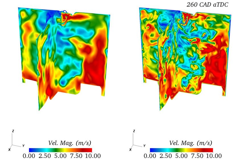
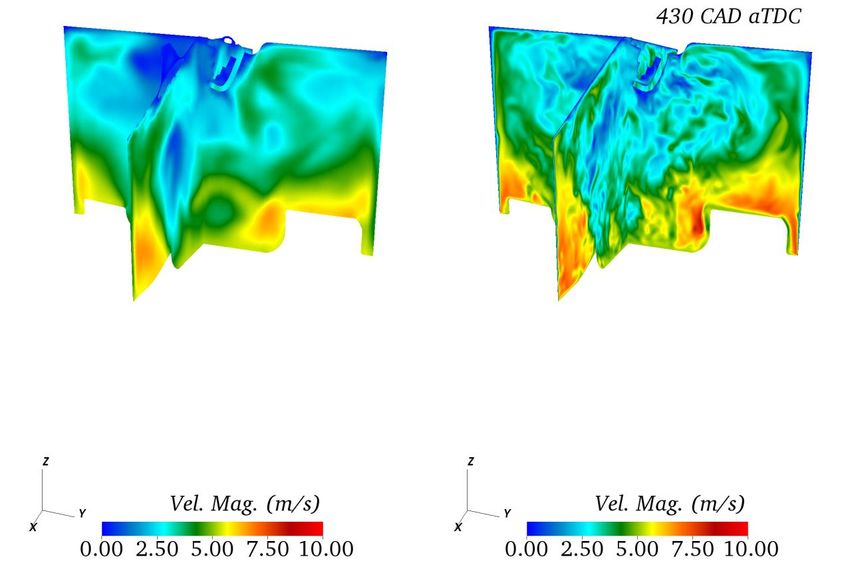
Accomplishment: High-fidelity simulations provide insights into wall boundary layers and turbulent kinetic energy distribution Thermal boundary layer evolution Turbulence distribution = ; = 260 CAD 300 CAD 260 CAD 300 CAD 420 CAD Appearance of smaller scale structures with increasing compression. Need higher resolution at higher compression. 360 CAD 420 CAD Left: Evolution of thermal boundary layer during a single cycle Right: Evolution of viscous length scale near the liner during compression/expansion Thermal and momentum boundary layer thicknesses reduce with increasing compression. Near TDC, boundary layer thicknesses (
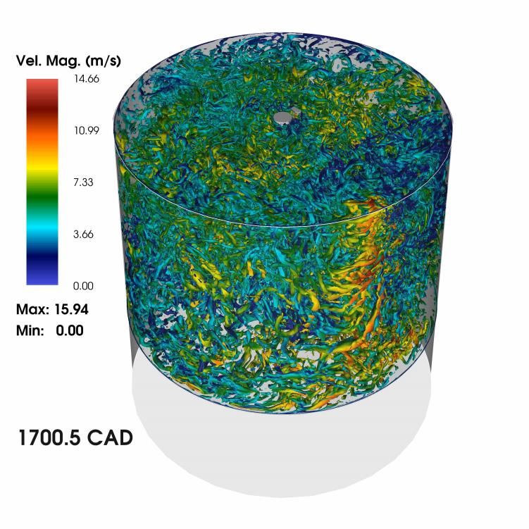
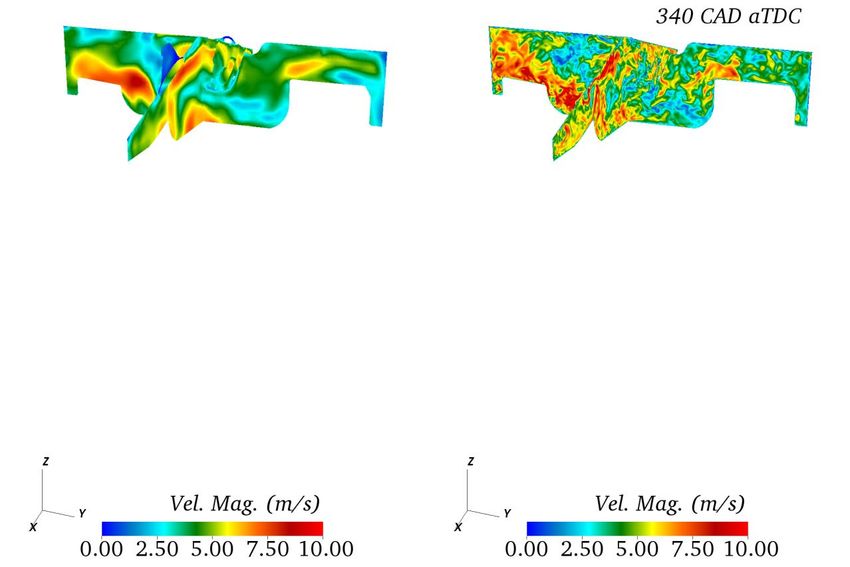
Accomplishment: DNS of Compression/Expansion Strokes of TCC-III
Engine with Experimental Validation
Objective: Perform DNS of motored engine flows to develop improved wall models 2020 U.S. DRIVE Highlight

 Evolution of heat flux at the probe
 Visualization of the λ2 iso-surfaces during the Flowfield near the head at CAD340 location on the head
 compression stroke showing the appearance
 of smaller scale flow features

• Performed DNS of compression/expansion strokes of TCC-III motored operation at 800 (FY20) and 500 RPM (FY21)
• Validated the flowfield and heat transfer using experimental measurements to increase confidence in the accuracy of the DNS. Overall,
 excellent agreement between DNS and experiments.
 10
Accomplishment: Developed Improved Heat Transfer Models using DNS Dataset Objective: Tune model parameters in the Rakopoulos model formulation to improve wall heat flux prediction by using DNS data at 500 and 800 RPM 1 1 1 1 11 1 1 + = log + +log + + − − loglog4040 + = ++ +B + 10.2384 0.4767 A 0.4767 A 0.4767 A 0.4767 A A-Priori Evaluation of DNS data to develop improved A-Posteriori Error Estimation of the tuned heat transfer model in Converge heat transfer models engineering LES Simulations % Error in heat flux prediction as a function of A and Implemented the tuned heat transfer B 800 RPM, CAD270 800 RPM, CAD300 model in Converge and performed multi- cycle engineering LES (min grid size=0.25 mm). Tuned heat transfer model leads to larger wall heat transfer as compared to the original model. Trends as expected as the a-priori analysis results. Tuned model leads to larger error in heat flux as compared to the original model; Performed tuning of the Rakopoulos heat needs further analysis. Shows transfer model using DNS dataset. importance of a-posteriori analysis. Changing (A,B) from (0.4747,10.2394) to Next step: Repeat analysis under fired (0.7,5.0) increases the heat flux and reduces conditions (FY22). model error to < 30% for near-wall grid sizes < Improved models will be shared across 1 mm across different RPMs and CADs PACE. 11
Accomplishment: Evaluated accuracy of baseline ECFM model using wall- resolved LES simulations in Nek5000 Objective: Implement ECFM combustion model in the Nek5000 engine simulation setup and validate against experimental dataset. Preliminary validation of ECFM for fired (stoichiometric propane) TCC-III at 500 RPM 1 3 3 Map flowfield Flame radius, = ∗ 4 Closed-cycle wall- Multi-cycle wall- resolved LES at a few resolved LES at 500 select cycles with RPM motored premixed fuel-air operation mixture Implemented the ECFM model in the Red: Simulation Nek5000 engine simulation setup Grey: Experiments with a spherical ignition source. Performed preliminary closed-cycle Validation of ECFM in a constant-volume simulations for the TCC-III fired turbulent premixed flame propagation from operation. Renou and Boukhalfa (CST, 2001). Baseline ECFM model fails to predict the peak pressure and late- stage combustion behavior. Motivates need for improving ECFM closure terms and ignition model 12
Accomplishment – GDI spray simulations with Nek5000 (1/2)
Objective: Implement spray modeling capabilities in Nek5000 to make the code ready to perform engine simulations in FY22
 [mm3/mm2]
• Performed high-resolution LES of ECN Spray G 8-hole
 injector, standard conditions. Nozzle Diameter 165
• Spray parameters were tuned to match experimental Injection pressure 20 MPa
 liquid penetration, based on the PLV=0.2e-3 threshold: Ambient density 3.5 kg/m3

 o Cone angle degree, plume direction, area contraction Ambient gas Nitrogen
 Ambient temperature 573 K
 coefficient and 1 parameter were varied.
 (Colmenares, J., Ameen, M., Patel, S. (2021) ASME ICEF) Fuel Iso-octane
 Injection time 0.76 ms
 Plume cone angle, ∘ , ∘
 Plume direction ∘
 Area contraction, 0.65
 LES, = 30∘
 Experiment

 Volume render of LVF from LES vs. Mie scatter, front view. PLV=0.2e-3 contours.
 Physical models Breakup model Value Order N=5

 Evaporation model Abramzon & Sirignano parameters Minimum Δ @ axis [mm] 0.033

 Breakup model KH-RT 0 0.61 # elements 270 k
 Droplet distortion TAB 1 80 # unique grid points 33.9 M
 0.4
 13
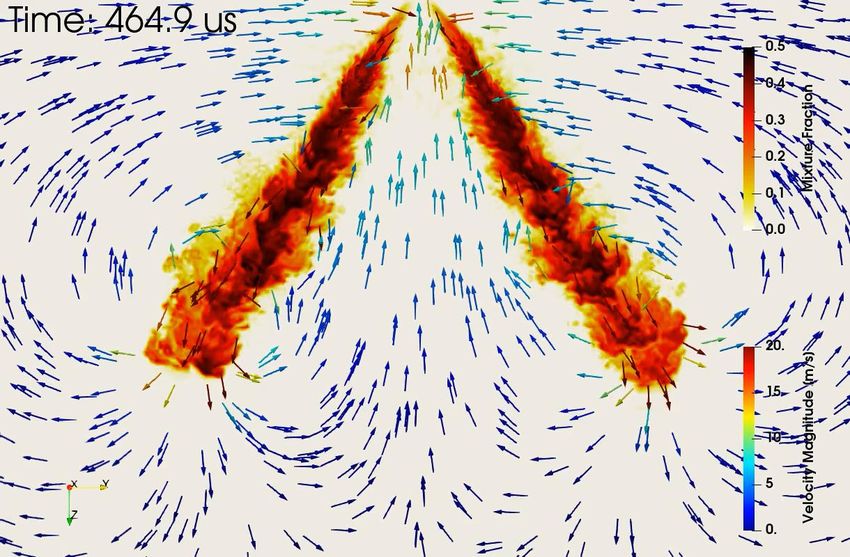
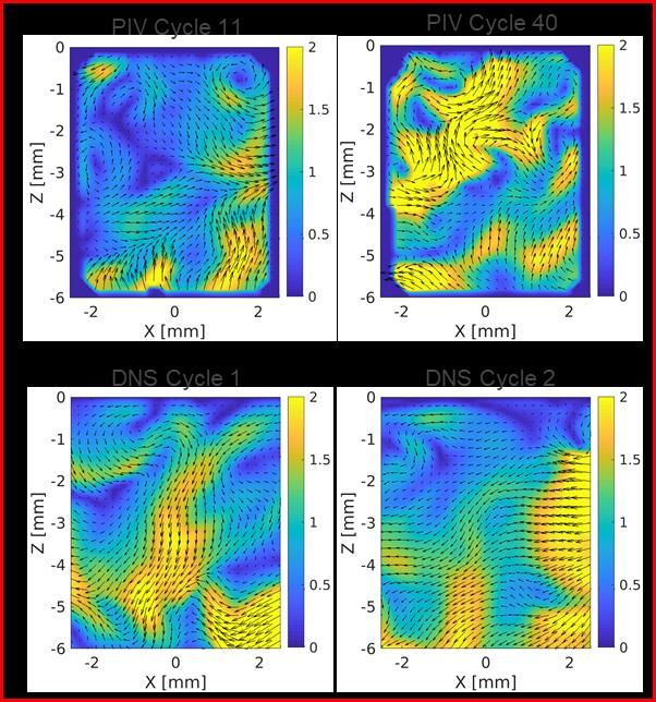
Accomplishment – GDI spray simulations with Nek5000 (2/2)

 Schematic of
 sampling locations

 SMD [ ]
 a) b) c)
 ∘
 Droplet Sauter mean diameters (SMD). a) LES with 25 cone angle, b) a) LES with
Gas mixture fraction, with vectors indicating velocity direction colored by 30∘ cone angle, c) PDI experiments (Parrish, 2015).
 velocity magnitude.
 • Inter-plume recirculation is well captured, though there is room for
 improvement.
 Axial velocity evolution at 15
 • Droplet sizes are under predicted towards the plume center, but well
 mm below the injector tip – PIV
 vs simulations captured towards the edge of the plume.
 • Even with high fidelity simulations, there are inaccuracies in the gas
 phase flowfield - need for improved Lagrangian spray models.
 • Demonstrated the readiness of Nek5000 to perform wall-resolved
 LES/DNS of fired engines (FY22) 14
Approach – Fully resolved simulations of flame/wet wall interactions, end- gas auto-ignition and detonation (SNL) o Gaps in existing models of flame/wet wall interactions and knock Flame wall interactions mainly focused on wall heat flux with little effort to model processes impacting emissions while utilizing quenching Peclet numbers for identifying the quenching zone that are only valid for dry walls Most knock models rely on presumed pdfs of local mixture fraction/enthalpy and there is a lack of high-fidelity DNS datasets, especially those valid for multi-component gasoline surrogates to verify the underlying assumptions o Low dimensional (1D/2D) fully resolved simulations allow exploration of wide thermochemical parametric space which is not possible with computationally expensive 3D DNS Identify the effects of various parameters on the overall trend of relevant physics Provide datasets for wide range of relevant conditions to aid model validation/development Numerical configuration for Flame/Wet-wall interaction Numerical configuration for End gas auto-ignition Turbulent Eddies Hot Spot Premixed Flame Premixed Flame propagation propagation 400-K 50 µm liquid fuel Stratified wall Adiabatic film Stoichiometric Gasoline-Air Fuel Vapor Gasoline-Air mixture Cold Spot wall mixture at 1100K and 50 atm 15 1: Pal et al. JERT, 140(10) 102205 (2018)
Accomplishments: Quantified quenching distances during flame-wet wall interaction
through fully resolved 1D simulations
 575 K
 140.00 650 K 6.00

 Local Quenching Equivalnce Ratio
 500 K
 120.00 5.00
 Quenching Distance (microns)

 100.00 4.00

 80.00 3.00

 60.00 2.00

 40.00 1.00

 0.00
 20.00

 500K
 575K
 650K

 500K
 575K
 650K

 500K
 575K
 650K

 500K
 575K
 650K
 0.00
 DW Hept Iso Tol DW Hept Iso Tol DW Hept Iso Tol Cases
 Cases

 • Wet walls, in general, lead to larger quenching distances with higher emissions than dry walls as previously observed
 by Tao et al. (IJER 2018)
 • Rich flammability limit is the dominant quenching mechanism in the presence of wet walls, in agreement with the
 observations of Tao et al. (IJER 2018)
 • The magnitudes of quenching distance (and hence quenching Peclet numbers) as well as quenching equivalence ratio
 are highly dependent upon the fuel wall film composition

 16
Accomplishments: Quantified emissions of soot precursors upon flame quenching in the
presence of wet walls

 • While the bulk gas composes of stoichiometric mixture, quenched layer consists of rich stratified mixture
 • Upon quenching, C6H6 production in the toluene case is accompanied by noticeable production of C14H14 unlike
 the iso-octane or n-heptane case
 • New PACE developed mechanism with more detailed PAH chemistry will be tested in FY 22
 17
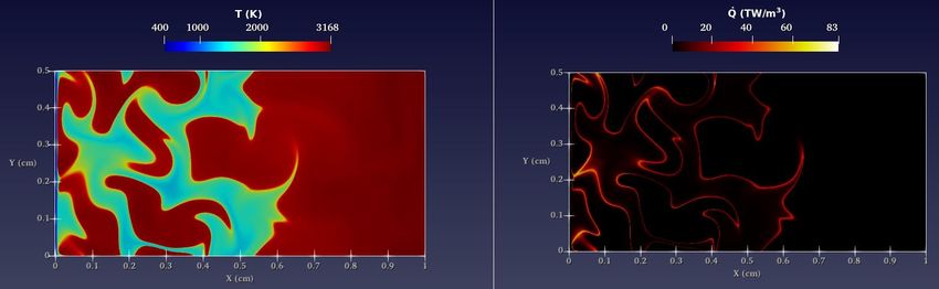
Accomplishments: Identified transition point from mild-knock to detonation through 2D DNS of end-gas auto-ignition 2 x×lT lT ( . ) • Mild knock observed for T < 5 mm with maximum 6 pressure (Pmax) seldom exceeding the equilibrium pressure (Peq) 5 • Results agree with previous studies using simpler 4 fuels/configurations 1 Pmax/PVN 3 o Recent DNS of knock phenomenon have revealed similar trends in 2D and 3D cases, with 3D cases leading to higher 2 maximum pressures due to higher interactions between originating detonation fronts 1 1 • Datasets will enable a-priori and a-posteriori evaluation of 0 the widely used transported Livengood-Wu model 0.11 0.115 0.12 0.125 0.13 0.135 + ∙ − = ሶ , t (ms) Φ 1 • Parametric variations in temperature length scales ( T ~ 50 − 100 × ሶ PDF,avg = Φ , Φ Φ , =1 =1 F where F = primary flame thickness) carried out at a fixed turbulence intensity ( ′ = 3.72 m/s), turbulence length scale ( 11 = 0.8 mm) and ሶ PDF,avg usually evaluated using presumed PDF of RMS temperature fluctuation ( RMS = 15 K) local mixture fraction and enthalpy depicted below: 2 • Detonation observed for T ≥ 5 mm with maximum pressure (Pmax) exceeding the Von-Neumann pressure (PVN) 1: Luong et al., (FTaC, 2020, PROCI 2020) 18 2: D’Adamo et al., Applied Energy, 2017
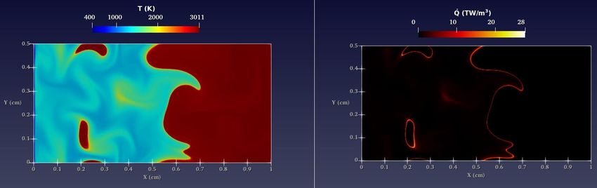
Accomplishments: 2D DNS of mild-knock under boosted GDI engine conditions

 = . ×
 • Smaller length scales of
 temperature
 stratification tend to
 result in smaller,
 isolated hot-spots
 igniting in conjunction
 • Eventually, volumetric
 = . × ignition of the
 unburned end-gas
 occurs
 • Not enough unburned
 mixture available for
 detonation to develop,
 Pmax ≈ Peq
 = .
 19
Accomplishments: 2D DNS of detonation under boosted GDI engine conditions

 = . × • Larger length scales of
 temperature stratification
 result in larger, isolated hot-
 spots igniting independently
 • Pressure waves emanating
 from the igniting hot-spots
 get reflected off of the wall
 and couple with the reaction
 front
 = . ×
 • As a result, there is an
 abrupt 20X increase in the
 PCJ heat release rate
 • Eventually a developing
 detonation emerges due to
 the availability of sufficient
 amount of unburned
 mixture, Pmax > PCJ
 =
 20
Response to Previous Year Reviewer’s Comments
 • While the reviewer appreciated the importance of super high-fidelity simulations
 to provide benchmarks against which to compare more affordable simulations, it
 is still not clear how results from this work will be used to develop sub -to
 improve engineering level simulations.
 In the current year, we demonstrated the use of DNS simulations to develop
 improved heat transfer and knock models. Plans are in place to implement these
 improved model into engineering level simulations
 • The team would benefit by engaging an OEM partner.
 We have held conversations with engine OEMs and plan to have them in the
 advisory board in FY22
 • This appears to be a collection of unconnected efforts with no coherent plan for
 integrating them or collaborating among them. The three efforts are aligned with
 the overall PACE effort, but they are not clearly coordinated with each other.
 We have improved coordination among the projects. The plan is to leverage the
 ASCR investments to provide high quality simulation datasets which will be used
 to develop improved submodels for spray, combustion, and heat transfer.

 21
Partnerships/Collaborations

PACE Collaboration
• Bill Pitz, Scott Wagnon (LLNL) – Skeletal/reduced mechanisms for PACE surrogates
• Russell Whitesides (LLNL) – Implement fast chemistry and transport solvers
• Lyle Pickett, Julien Manin (SNL) – Spray vessel experiments
• Magnus Sjoberg (SNL) – Optical engine experiments

External Collaborators
• Pointwise Inc. – Fast and efficient mesh generation for Nek5000
• Paul Fischer (UIUC) – Solver development for compressible version of Nek5000
• Joe Insley, Silvio Rizzi (ANL-LCF) – Integrate in-situ visualization capabilities into Nek5000
• Kris Rowe (ANL-LCF) – GPU version of Nek5000
• Matthias Ihme (Stanford) – Implement non-equilibrium wall models in Nek5000
• Chao Xu, Pinaki Pal (ANL) – Submodel implementation in Nek5000
• PELE Team (LBNL, NREL, ORNL, SNL) – Submodel implementation and scalability in PELE

 22
Remaining Challenges and Barriers

• PACE-wide barriers discussed in ACE138
• Coupling with commercial CFD codes:
 o Need to develop workflows to perform hybrid DNS/LES or LES/RANS simulations by coupling with
 commercial or open-source low-order CFD codes
 o Use data generated from DNS and wall-resolved LES simulations to improve submodels in
 commercial codes
• Size and accuracy of skeletal/reduced mechanisms for PACE fuel surrogates:
 o Collaborations with the PACE combustion/kinetics team to develop compact mechanisms (~100
 species) with sufficient accuracy for the high-fidelity DNS simulations
• Computational resources may be limited:
 o ALCC and INCITE proposals to be submitted for access to DOE leadership class machines
 o Long queue times on leadership-class machines
• Proper archiving of data:
 o High fidelity simulations will generate >100 TB of data. There is a need to develop efficient data
 analytics and ML tools, and workflow to share this data across the PACE program
 23
Proposed Future Work- ANL

• Spray Model Development in Nek5000
 o Implement improved spray/wall interaction models (FY22 Q1)
 o Corrected Distortion, multi-component evaporation models from Sandia (FY22 Q2)
 o One-way coupling injection method using maps from internal-nozzle flow simulations from ANL (FY22
 Q4).
 o Couple spray modeling with engine framework to simulate Sandia DISI engine to study CCV (FY22-
 FY23).
• Combustion Model Development in Nek5000
 o Improve submodels for flame propagation and flame-wall quenching using Chen’s DNS dataset (FY21-
 FY22)
• Multi-cycle LES/DNS of the Sandia optical DISI engine under fired conditions [FY21-FY23]:
 o Improve understanding on causes of cyclic variability in flow, mixing, spray and combustion
 o Improve flame-wall interaction and wall heat transfer models
 o Archive numerical setup, flow and thermal data
 Any proposed future work is subject to change based on funding levels 24
Proposed Future Work- SNL

• Flame wall interaction
 o Liquid film evaporation model implementation
 o 2D simulations with side wall quenching
 o Hybrid Method of Moments implementation
 o New gasoline surrogate (TPRF-Ethanol/PACE20) chemical mechanism to accurately capture PAH and
 subsequently soot formation
• End gas autoignition
 o Implement a scalar transport equation in S3D resembling the widely used transported Livengood-Wu
 integral model to assess its accuracy to predict knock in the presence of turbulence and
 temperature/mixture stratification
 o Parametrize laminar flame speeds at auto-ignitive conditions under the effect of time evolving
 pressure towards predictive turbulent flame speed models

 Any proposed future work is subject to change based on funding levels 25
Summary
Relevance
• Cyclic variability mitigation and reducing cold start emissions are barriers to attaining higher efficiency for dilute SI combustion

Approach
• Leverage ASCR funded codes Nek5000 and S3D to perform high-fidelity simulations of the flow, spray and combustion processes in SI
 engines
• Adapt Nek5000 code into a simulation platform tailored for ICE simulations
• Multi-fidelity approach for improved wall heat transfer, combustion and emission models

Accomplishments
• Performed multi-cycle LES of the Sandia DISI and demonstrated potential causes of CCV
• DNS of the compression/expansion stroke performed on >400M grid points on >51,000 processors - Largest ever engine simulation
• Implemented spray submodels in Nek5000 and demonstrated the accuracy in modeling multi-hole evaporating sprays
• Implemented ECFM combustion model in Nek5000 and modeled fired engine simulations
• Demonstrated that one-way coupled soot models cannot capture soot onset or growth under pyrolysis conditions
• Simulated the chamber pre-burn for soot wall film experiment

Future Work
• Multi-cycle LES of the Sandia optical DISI engine with spray and combustion
• Improve combustion submodels in Nek5000 using Chen’s DNS dataset
• 2D DNS with S3D of flame wall interaction for a range of gasoline fuel surrogate: TPRF-Ethanol and PACE20
• 3D DNS with S3D of end gas ignition and flame wall interaction for selective conditions.

 26
• TECHNICAL BACKUP SLIDES

 27
Approach: DNS/LES to Develop Submodels
 • Adapt Nek5000 code into a simulation platform tailored for ICE simulations (ANL)
 o Provide an accurate platform for testing and developing ICE-specific turbulence, spray and combustion submodels
 o Perform multi-cycle, high-fidelity wall-resolved LES to identify the root causes of cyclic variability and provide the
 understanding needed to design for their minimization
 o DNS of compression and expansion strokes to evaluate and improve wall and heat transfer models
 • Multi-fidelity approach for improved combustion and emission models (SNL)
 o 1D and 2D DNS with large parametric variations to gain physical insight
 o Full 3D DNS simulations to provide high-fidelity and high quality data for developing submodels for flame propagation, flame-
 wall interaction, and emissions
 o Physics-based and data-driven sub-model development for both RANS/LES
 • The improved submodels will be implemented back into commercial codes for use in OEM workflows Use in OEM workflow

 Boundary High-fidelity Improved ignition, flame
Combustion vessel Validation data conditions data propagation, flame-wall
 LES Simulation DNS Simulation interaction, and emission
 experiments
 Nguyen Chen submodels
 Pickett/Manin

 Optical engine Multi-cycle wall- DNS of closed- Improved wall and heat
 experiments resolved LES cycle transfer models
 Sjoberg Ameen Initial Ameen High-fidelity
 Validation data
 conditions data
 28
TCC-III Experimental Setup

Heat Flux Probe and PIV Measurement Planes

 29
Approach – DNS simulation of flame wall quenching, end-gas autoignition,
 flame deflagration and detonation
• 3D DNS simulations using gasoline surrogate are extremely expensive
 o Chemical mechanism consists of 100s of species
 o End gas auto-ignition simulations require high temporal and spatial resolution due to fast propagating reaction fronts coupled with
 pressure waves
 o Flame wall interaction requires large parametric variations because of thermochemical mixture sensitivity
• Computationally efficient 1D-2D DNS is utilized for large parametric variations
 o Reduced TPRF-Ethanol gasoline mechanism with 165 or 118 species1
 o Variations in temperature, pressure, mixture stratification
 o Detailed analysis of flame quenching, auto-ignition, flame detonation and deflagration behavior
 o Identify relevant cases for 3D DNS simulations
 Flame wall interaction DNS configuration End gas auto-ignition DNS configuration
 Turbulent Eddies Hot Spot

 Premixed Flame Premixed Flame
 propagation propagation
 400-K
50 µm liquid fuel Stratified wall Adiabatic
film Stoichiometric Gasoline-Air
 Fuel Vapor Gasoline-Air mixture Cold Spot wall
 mixture at 1100K and 50 atm

 30
 1: Pal et al. JERT, 140(10) 102205 (2018)
Accomplishments: 1D DNS flame-wall interaction simulations S3D/CONVERGE setup
validation
• To validate the permeable wall boundary S3D CONVERGE
 condition in S3D, numerical results from S3D
 and CONVERGE for the dry wall case were
 compared.
• Wet wall boundary conditions implemented
 as permeable wall condition based on fuel
 evaporation rate calculated by CONVERGE.
• High order S3D DNS code δq
 o 8th order central differencing scheme
 o 4th order explicit Runge-Kutta time integrator
• CONVERGE
 Dry wall quenching characteristics
 • PISO algorithm with fully conserved
 Quenching Peclet
 formulation Code distance (δq) number
 [µm] (Peq)
 • 1st order implicit Euler time integration
 scheme S3D 32 3.04

 • 2nd order flux blending scheme
 CONVERGE 29 2.77
 • Variable time step sizes

 Despite the difference in the numerical implementation, both codes are in good agreement 31
KNOCK PREDICTION • Transported Livengood-Wu integral , • is tabulated a priori. Min. Max. Step + ∙ − = ሶ Temperature 500 K 1500 K 10 K • Solving the reaction rate ሶ with sub-grid fluctuation, Pressure 10 bar 70 bar 5 bar Φ Phi 0.4 2 0.1 1 ሶ , = Φ , Φ Dilution 0 0.2 0.05 Φ , =1 =1 • Auto-Ignition volume: total in-cylinder • Local PDF of mixture fraction and enthalpy, volume where reaches 1. D’Adamo et al., Applied Energy, 2017 32
You can also read