Driver Assistance Systems - Technology Guide - Oem1stop.com
←
→
Page content transcription
If your browser does not render page correctly, please read the page content below
Driver Assistance Systems
Technology Guide
Preface2

                                               Driving systems                                               3
                                               Overview3
                                               Blind Spot Assist/Active Blind Spot Assist              4
                                               Lane Keeping Assist/Active Lane Keeping Assist          6
                                               DISTRONIC/DISTRONIC PLUS                                8
                                               DISTRONIC PLUS with Steer Assist                       12
                                               Night View Assist/Night View Assist PLUS               14
                                               Adaptive Highbeam Assist/Adaptive Highbeam Assist PLUS 17
                                               Cruise control and Speedtronic                         19
                                               Downhill Speed Regulation                              21
                                               Speed Limit Assist/Traffic Sign Assist                 22
                                               ATTENTION ASSIST                                       24

                                               Parking systems                                              26
                                               Overview26
                                               PARKTRONIC/PARKTRONIC with Parking Guidance 27
                                               Active Park Assist                          29
                                               Reversing camera                            31
                                               360° camera system                          34

                                               Driving Safety Systems                                       36
                                               Overview36
                                               Brake Assist System (BAS/BAS PLUS)                            37
                                               Adaptive Brake Assist                                         38
                                               Brake Assist System (BAS PLUS) with Intersection Assist       39
                                               PRE-SAFE® brake                                               41
                                               PRE-SAFE® PLUS                                                43
                                               COLLISION PREVENTION ASSIST/ COLLISION PREVENTION ASSIST PLUS 45

                                               Annex47
                                               Information and copyright                                    47

Driver Assistance Systems | Technology Guide                                                                       1
Preface

Dear Reader,

Driver assistance systems make driving easier by providing
assistance and protection to the driver – and they help to
make the Mercedes-Benz brand even more fascinating than
before. Bring this fascination for the brand to life for your
customers in your role as a service specialist.

This manual provides all of the important information you
need about the driver assistance systems found in Mercedes-
Benz cars. It is compact, clearly arranged and contains the
most important facts about their operation as well as practi-
cal tips for service and diagnosis. It will help you to perform
in accordance with the motto of "The Best or Nothing" in your
customer consultations and when preparing your service
jobs.

Global Service & Parts wishes you good luck!

Daimler AG
Retail Operation (GSP/OR)

                                                                  bbNote
                                                                  This manual is not subject to the ongoing update
                                                                  service. When working on the vehicle, always use the
                                                                  most up-to-date workshop aids (e.g. EPC net, WIS net,
                                                                  DAS, special tools) for the vehicle in question.

                                                                  See the respective sales documentation for country-
                                                                  specific special considerations.

2                                                                                       Driver Assistance Systems | Technology Guide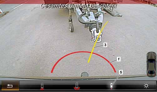
Overview

                                                                                                                                  Driving systems
Driving systems                           Abbreviation   SA code   Model series

Blind Spot Assist                         BSM            234       117, 164, 166, 172, 176, 197, 204 MOPF, 207, 212, 218,
                                                                   216/221 up to MY 2009, 246, 251 MOPF

Active Blind Spot Assist                  BSM+           237       166, 204 MOPF, 207, 212, 216 MOPF, 218, 221 as of MY
                                                                   2010, 222, 231

Lane Keeping Assist                       ALDW           476       117, 166, 172, 176, 204 MOPF, 207, 212, 216 MOPF,
                                                                   218, 221 MOPF, 231, 246

Active Lane Keeping Assist                LDP            238       166, 204 MOPF, 207, 216 MOPF, 212, 218, 221 MY 2011,
                                                                   222, 231

DISTRONIC                                 DTR            219       209, 211/219, 220/215, 230, 164/251

DISTRONIC PLUS                            DTR+           233/239   166, 172, 204 MOPF, 207, 212/218, 221/216,
                                                                   207/212 MOPF, 222, 231 (code 233)
                                                                   117, 176, 246, 463 MOPF (code 239)

DISTRONIC PLUS with Steer                 DTR+Q          266       207/212 MOPF, 222
Assist

Night View Assist                         NV             610       216, 221

Night View Assist PLUS                    NV+            610       166, 212, 218, 216/221 MOPF, 222, 231

Adaptive Highbeam Assist                  IHC            608       117, 166, 172, 176, 204 MOPF, 207, 212, 216 MOPF,
                                                                   218, 221 MOPF, 231, 246

Adaptive Highbeam Assist                  IHC+           628       207/212 MOPF, 222
PLUS

Cruise control                            TPM            440       169, 203 up to MY 2005, 245 – non-braking cruise control
                                                                   117, 164, 166, 171, 172, 176, 203, 204, 207, 209, 211,
                                                                   212, 216, 218, 219, 221, 222, 230, 231, 246, 251 –
                                                                   braking cruise control

Speedtronic                               LIM            440       169, 203 up to MY 2005, 245 – non-braking variable
                                                                   speed limiter
                                                                   117, 171, 172, 176, 203, 204, 207, 211, 212, 216, 218,
                                                                   219, 221, 222, 230, 231, 246, – braking variable speed
                                                                   limiter

Downhill Speed Regulation                 DSR            4301      164, 166, X204

Speed Limit Assist                        SLA            513       117, 166, 172, 176, 204 MOPF, 207, 212, 216 MOPF,
                                                                   218, 221 MOPF, 231, 246
                                                                   As of MY 2012 Speed Limit Assist 1.5
                                                                   207/212 MOPF, 222 Traffic Sign Assist

ATTENTION ASSIST                          AA             538       117, 166, 172, 176, 204 MOPF (only with code 442), 207,
                                                                   212, 216 MOPF, 218, 221 MOPF (without S400 Hybrid),
                                                                   222, 231, 246

1 Included with off-road package (code 430)

Driver Assistance Systems | Technology Guide                                                                                  3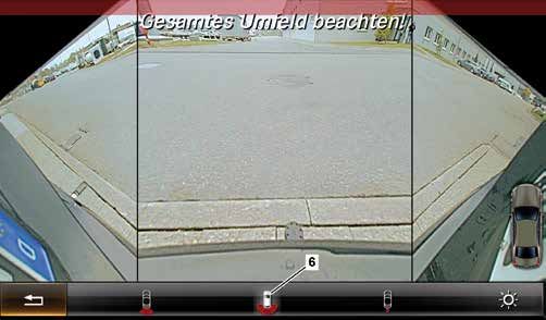
Blind Spot Assist/Active Blind Spot Assist
Driving systems

                  Features                                                                System limits
                  The Blind Spot Assist system developed by Mercedes-Benz                 False warnings can be issued near guardrails or concrete si-
                  uses radar technology to monitor the area 3 m to the side               dewalls and the system is automatically shut off in the vicinity
                  and 3 m to the rear of the vehicle. The system becomes ac-              of radio astronomy facilities by means of the navigation data.
                  tive as of 30 km/h and the yellow visual indicator in the out-
                  side mirrors then disappears. If the system detects another             Overtaking vehicles are reliably detected up to a speed diffe-
                  vehicle in the blind spot, this is indicated in the first stage         rential of 35 km/h. During overtaking, warnings are issued
                  by a red hazard warning triangle lighting up in the respective          up to a speed differential of 12 km/h. Vehicles with a higher
                  outside mirror. If the driver sets the turn signal despite the          speed differential may - under certain circumstances - be de-
                  visual warning, an acoustic warning is issued additionally in a         tected too late or not at all. As a consequence, any warning
                  second stage.                                                           may then come too late or not at all.

                  The Active Blind Spot Assist system builds upon the functio-            At a vehicle speed of > 200 km/h, and in the event of heavy
                  nality of Blind Spot Assist. This system can additionally help          longitudinal or lateral acceleration, only a warning is issued
                  to avoid accidents in a third stage by performing a single-             and no course-correcting brake system intervention is
                  sided, targeted brake application to correct the course of the          performed.
                  vehicle in a vehicle speed range of 30 - 200 km/h.

                  The driver is able to abort the course-correcting brake sys-
                  tem intervention by countersteering at a steering angle of
                  > 5° or by depressing the accelerator pedal to change its
                  position by > 10%.

                  Extended functionality on BR 222
                  The readiness indicator is displayed on the instrument cluster
                  and not in the form of a visual indicator consisting of a yellow
                  triangle in the outside mirror. The warning indicator is dis-
                  played in the outside mirror and on the instrument cluster.

                                                                                             bbService information
                                                                                             No calibration is required. When accident repairs are
                                                                                             performed, the paint coat thickness on the bumper
                                                                                             must be observed and filler repairs may not be carried
                                                                                             out in the area of the sensors on the bumper.

                                                                         P54.33-3399-00
                  Instrument cluster display for Blind Spot Assist

                  4                                                                                                  Driver Assistance Systems | Technology Guide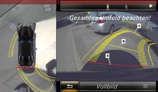
Blind Spot Assist/Active Blind Spot Assist

                                                                                                                                                                                 Driving systems
Blind Spot Assist components without additional control                             Components of Active Blind Spot Assist:
unit:                                                                               • 2 x NBR in outer rear bumper
• 2 x short range sensors (NBR) in outer rear bumper                                • 1 x radar sensors control unit (SGR)
                                                                                    • 1 x long range radar
Blind Spot Assist components with additional control
unit:                                                                               Diagnosis
• 2 x NBR in outer rear bumper                                                      • Radar sensors control unit (SGR)
• 1 x radar sensors control unit (SGR)                                              • Outer left rear intelligent radar sensor control unit
• On BR 221 before MOPF: 2 x NBR in front bumper,                                      (IRS-HLA)
    4 x NBR in rear bumper                                                          • Outer right rear intelligent radar sensor control unit (IRS-
                                                                                       HRA) (with Blind Spot Assist without additional control
                                                                                       unit)

                                                                                                                                  2

                       1

                                                 3m

                                    3m

                                                                       A                                B                                      C

                                                                                                                                                                P54.33-3400-00
Active Blind Spot Assist
1   False warnings may be issued near guardrails or concrete sidewalls in           A   Warning stage 1
    roadwork zones.                                                                 B   Warning stage 2: If the driver sets the turn signal despite the warning, the
2   The system shuts off automatically in the vicinity of certain radio astronomy       red triangle flashes and an acoustic warning also sounds in the instrument
    facilities by means of navigation data.                                             cluster.
                                                                                    C   Warning stage 3: Course-correcting, single-sided brake system intervention if
                                                                                        risk of side collision detected. (Only with Active Blind Spot Assist)

Driver Assistance Systems | Technology Guide                                                                                                                                5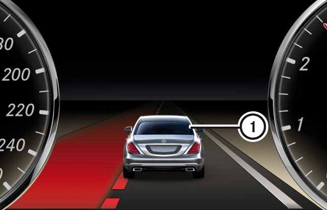
Lane Keeping Assist/Active Lane Keeping Assist
Driving systems

                  Features
                  The Lane Keeping Assist system from Mercedes-Benz helps                  The Active Lane Keeping Assist system also intervenes
                  the driver to keep the vehicle in its lane. The multifunction ca-        when the vehicle is threatening to cross over continuous
                  mera recognizes the lane markings through contrast compa-                lines. If the driver does not respond to the haptic warning in
                  rison. If the system detects that the vehicle is unintentionally         stage 1, the system attempts to keep the vehicle in its lane
                  leaving its lane, a vibration motor in the steering wheel warns          by performing a single-sided, course-correcting brake system
                  the driver with a haptic signal (3x pulsation). The system is            intervention using the ESP.
                  activated as of a vehicle speed of 60 km/h and indicates that
                  it is ready to operate by means of an inverted or green icon             No intervention is performed by the Active Lane Keeping As-
                  on the instrument cluster. The Lane Keeping Assist system                sist system if a trailer is coupled, if the ESP is off, in run-flat
                  also detects single-sided lane markings.                                 mode (tires) or if there are single-sided lane markings.

                  No warnings are issued when a turn signal is set, on narrow              As of model series 207/212 MOPF and 222, the system
                  bends, directly after a warning has been issued, for ambi-               also performs a course-correcting, single-sided brake system
                  guous markings (yellow/white roadworks markings), during                 intervention with non-continuous lane markings if there is
                  dynamic driving (e.g. heavy acceleration/braking), kickdown              a risk of collision with vehicles on the adjacent lane due to
                  or rapid steering. Deliberate corner cutting results in a de-            oncoming traffic, vehicles overtaking rapidly, parallel traffic
                  layed warning. Earlier warnings are issued on the outside of             or stationary vehicles. If a vehicle is detected close behind in
                  bends and on narrow lanes.                                               the same lane (tailgating scenario) or the system detects an
                                                                                           obstacle in the same lane, e.g. cyclists, the course-correcting
                  As of model series 246 and 166, different operating modes                brake system intervention may be aborted.
                  can be set on the instrument cluster.

                                                                                              bbService information
                                                                                               The camera has to be re-calibrated if the windshield is
                                                                                               replaced, the camera is replaced or the suspension is
                                                                                               modified.

                                                                                               Special tool Romess Rogg 0840-10, calibration target
                                                                                               for Night View Assist.

                                                            1
                                                                          P46.10-3366-00
                  Steering wheel with vibration element
                  1   Vibration motor

                  6                                                                                                     Driver Assistance Systems | Technology Guide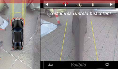
Lane Keeping Assist/Active Lane Keeping Assist

                                                                                                                                              Driving systems
System limits                                                             Components
Warnings are only issued if the lane is clearly recognizable.             • 1 x multifunction camera
Leaves, snow etc. can conceal the lane and limit the function             • 1 x vibration motor in steering wheel
of the system. Functional impairments can also be caused                  • Radar sensors control unit (SGR) (only with Active Lane
by the sun shining directly on the camera lens, heavy rain or               Keeping Assist)
other visual obstructions e.g. fog. If the vehicle in front is too
close, the camera cannot recognize the lane markings be-                  Additional components as of model series 207/212
cause they are concealed by the vehicle in front.                         MOPF and 222 for recognizing occupied adjacent lanes
                                                                          • 1 x stereo multifunction camera
Course-correcting interventions are only performed by the                 • 1 x front long range radar
Active Lane Keeping Assist system if the lane markings are                • 4 x short range radar (2 each at front and rear)
continuous and a haptic warning has previously been issued.               • 1 x rear multi-mode radar
The maximum change in longitudinal and lateral acceleration
is approx. 2 m/s². Furthermore, no interventions are perfor-              Diagnosis
med on tight bends with a curve radius of < 150 m. In the                 • Multifunction camera (MFK)
case of BR 207/212 MOPF and 222, the system can perform                   • Radar sensors control unit (SGR)
a course-correcting intervention with non-continuous lane                 • Guided calibration via Xentry Diagnostics
markings under certain circumstances (e.g. if there is onco-
ming traffic in the lane).

The system operates in a vehicle speed range of 60 -
200 km/h. As of a speed of > 200 km/h, haptic warnings
are issued only.

                                                         P54.33-3401-00                                                      P54.33-3402-00
Instrument cluster display                                                Installation location of multifunction camera
1   Systems vehicle                                                       1   Multifunction camera

Driver Assistance Systems | Technology Guide                                                                                             7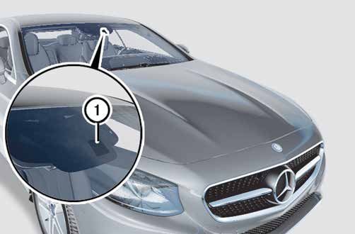
DISTRONIC/DISTRONIC PLUS
Driving systems
Features Additional functions
The DISTRONIC and DISTRONIC PLUS systems from On vehicles with code 233 as of MY 2011, the system is able
Mercedes-Benz ensure that the systems vehicle maintains a to suppress acceleration commands if the target vehicle is
preset time interval to vehicles in front. The radar-assisted lost on freeway exits or traffic circles. The multi-object con-
adaptive cruise control system maintains a preset speed. If trol function (BR 221/216, 212, 218, 207 with code 233
the distance to the vehicle in front reduces, the acceleration as of MY 2011) enables the system to respond earlier to
is reduced or the system activates the brakes if necessary. vehicles which cut into the lane and to perform situation-
As soon as the traffic situation allows it again, the system au- dependent braking based on the second vehicle ahead as
tomatically accelerates back up to the previously set speed. well as early and dynamic acceleration in the case of lane
changes. Here, activation is carried out by actuating the turn
The time interval can be steplessly adjusted using the cruise signal function.
control lever in a range of 1 – 2 s. The system brakes and ac-
celerates automatically, but is not able to react to stationary Additional extended functionality as of BR 207,
vehicles. The potential braking effect is limited to approx. 30 212 MOPF and 222
% of the maximum possible braking power of the vehicle (ap- More dynamic acceleration is carried out in the dynamic
prox. 40 % with DISTRONIC PLUS and 50 % with DISTRONIC transmission mode. Braking is carried out with up to approx.
PLUS with Steer Assist). If the braking power which can be 50 % of the max. braking power of the vehicle. The system
applied by the DTR or DTR+ system is not adequate, the dri- takes into account the fact that overtaking on the right on
ver is warned visually and acoustically. The control response freeways or similar roads is not permitted above 80 km/h
of the DISTRONIC system is determined by the distance to and adjusts the speed to the traffic line in the left-hand lane.
the target object, the vehicle speed and the steering angle. In countries with left-hand traffic, the system prevents overta-
king in the left-hand lane.
P30.30-2660-00
Installation situation of DTR+ radar sensors (code 233)
1 Short-range radar sensor
2 Long-range radar sensor
8 Driver Assistance Systems | Technology Guide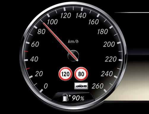
DISTRONIC/DISTRONIC PLUS

                                                                                                                              Driving systems
DISTRONIC sensor types: ARS 210 and as of MY 2011
(BR 164/251) ARS 310

Components
• 1 x Long-range radar sensor with integrated control unit

Diagnosis
• Distronic (DTR)

                                                                                                             P30.30-2661-00
                                                             ARS 210 sensor

DISTRONIC PLUS sensor types: LRR 3 (code 239) and
ARS 310/315/316 (code 233)

Components
• 1 x long-range radar sensor with integrated control unit
• 2 x short-range radar (code 233 only)
• 1 x radar sensors control unit (SGR) (code 233 only)

Diagnosis
• Distronic (DTR)
                                                                                                             P30.30-2662-00
• Radar sensors control unit (SGR) (code 233 only)           Sensor LRR 3

                                                                                                             P30.30-2663-00
                                                             ARS 310 sensor

    bbService information                                       bbService information
    Manual calibration must be performed on sensor type          Special tool for sensor type LRR 3:
    ARS 210, see AR30.30-P-1000R.                                Beissbarth Order no. 1690380004 or Romess Rogg
                                                                 Order no. 09807-10
    Special tool: Romess Rogg, Order no. 09803

    A calibration drive must be performed for sensor type
    ARS 310/315/316, see Xentry Diagnostics.

Driver Assistance Systems | Technology Guide                                                                             9
DISTRONIC/DISTRONIC PLUS
Driving systems
m
500
500
30 m m
60 m
200 m
P30.30-2664-00
Detection range of DISTRONIC
Nahbereich PLUS mit
Reichweite with 80°
ARS 310 long-range radar sensor and short-range sensors
Erfassungswinkel
Mittelbereich
Short range withReichweite mit 60° Erfassungswinkel
80° detection angle Long range with 18° detection angle
Fernberich Reichweite mit 18° Erfassungswinkel
Medium range with 60° detection angle Camera range with 35° detection angle
Kamera Reichweite mit 35° Erfassungswinkel
30 m
100 m
200 m
P30.30-2665-00
Nahbereich
Detection Reichweite
range of DISTRONIC PLUS mit
with 30°
LRR 3Erfassungswinkel
radar sensor
Mittelbereich Reichweite mit 16° Erfassungswinkel
Short range with 30° detection angle Long range with 12° detection angle
Fernberich Reichweite mit 12° Erfassungswinkel
Medium range with 16° detection angle
10 Driver Assistance Systems | Technology GuideDISTRONIC/DISTRONIC PLUS
Driving systems
System limits
The DTR and DTR+ systems operate in a certain vehicle In the event of heavy snowfall or icing on the sensor cover in
speed range (see table). Cross-traffic is not detected by the radiator grille, the system may shut off. This is indicated
the system and the detection of narrow vehicles is not fully by the message "System currently unavailable".
reliable. On roads which slope down at the sides, the coun-
tersteering changes the sensing angle. Stationary obstacles, In addition, the DTR+ system can shut off in the vicinity of ra-
e.g. signs on bends, can trigger collision warnings. A further dio astronomy facilities. Manual deactivation may sometimes
limitation is in the detection of vehicles on bends, whereby be necessary here (code 233 only). Similar radar technology
brake applications can be performed unexpectedly or with a in use by other road users or e.g. toll systems, automatic
delay. Furthermore, vehicles driving at an offset may not be door systems, can also cause the system to shut off.
detected, which can cause the distance to the vehicle in front
to become too short.
System Model series Sensor Code Vehicle speed range Maximum possible
deceleration
DISTRONIC 209, 211, 219, 220, ARS 210 219 30 – 180 km/h 30 %
215, 230
164, 251 as of ARS 310 219 0 – 200 km/h 30 %
MY 2011
DISTRONIC PLUS 166, 172, 204 MOPF, ARS 310 233 0 – 200 km/h 40 %
207, 212, 218, 216,
221, 231
222, ARS 315 233 0 – 200 km/h 50 %
207/212 MOPF ARS 316 233 0 – 200 km/h 50 %
117, 176, 246, LRR 3 239 0 – 200 km/h 40 %
463 MOPF
Driver Assistance Systems | Technology Guide 11DISTRONIC PLUS with Steer Assist
Driving systems
Features System limits
The extended functionality of DISTRONIC PLUS with Steer The lane guidance function is aborted if the lane markings
Assist helps the driver to keep the vehicle in the center of cannot be clearly recognized (e.g. due to multiple markings
the lane on straight roads and minor bends through the ap- in roadwork zones), if the markings are concealed (snow,
plication of steering torque in a targeted manner and makes leaves etc.), if the contrast to the road surface is too low and
it easier to follow the vehicle in front in traffic jam situations in heavy rain or thick fog. The object guidance function is
with the "Stop & Go Pilot" function. aborted if the vehicle in front changes lane or the distance to
passing or parked vehicles is too short. No assistance is pro-
The vehicle is kept the center of the lane either by lane or vided by the Steer Assist function if a collision with a vehicle
object guidance. The function requirements for lane guidance in the blind spot is imminent, the driver actively changes lane,
are a maximum speed of 200 km/h while the stereo multi- the turn signal is operated, the driver does not steer by them-
function camera is able to detect lane markings on both si- selves for an extended period of time or the driver takes his/
des. The lane width must be ≤ 4.2 m and the maximum offset her hands off the steering wheel.
to the center of the lane cannot exceed 40 cm at the start
of a control operation. Steering assistance is canceled when
the turn signal is actuated. An additional function require-
ment for object guidance is a vehicle speed of max. 60 km/h
while the stereo multifunction camera is able to detect the
position of the vehicle in front. The distance to the vehicle in
front must be between 1.0 - 40.0 m (speed-dependent) and
the offset to the vehicle in front can be max. 0.35 m at the
start of a control operation.
The "Stop & Go Pilot" function operates in the range up to
60 km/h. If the lane marking is not detected or missing,
the vehicle is kept in the center of the lane through object
guidance.
The torque sensor of the electric power steering records the
steering torque applied by the driver (hands-off detection)
and the signal is evaluated by a control unit. If no steering
torque or an insufficient steering torque is measured for ap-
prox. 10 s, a visual warning is issued in the first stage. After a
further 5 s, an acoustic warning is output in the second stage
and the Steer Assist function is deactivated. The DISTRONIC
PLUS system still remains active in this case.
P54.33-3403-00
Instrument cluster indicator of DISTRONIC PLUS with Steer Assist
1 Steer Assist icon
12 Driver Assistance Systems | Technology GuideDISTRONIC PLUS with Steer Assist
Driving systems
Components
• 1 x stereo multifunction camera bbService information
• 1 x long range radar Guided calibration for multifunction camera and long-
• 4 x short range radar (2 each at front and rear) range radar with Xentry Diagnostics.
• Radar sensors control unit (SGR)
Diagnosis
• Stereo multifunction camera (MFK)
• Radar sensors control unit (SGR)
1 4 1
1 3 12
P30.30-2666-00
Components of DISTRONIC PLUS with Steer Assist
1 Short range radar 3 Stereo multifunction camera
2 Long range radar 1 4 Radar sensors control unit
Driver Assistance Systems | Technology Guide 13Night View Assist/Night View Assist PLUS
Driving systems
Features Extended functionality as of MY 2014 (BR 222, 231)
The Night View Assist and Night View Assist PLUS systems The system was extended with a thermal imaging camera
from Mercedes-Benz are infrared light-based camera sys- which can recognize relevant people at a range of up to 160
tems which are used to detect obstacles and hazards at an m and animals (e.g. deer, cows, horses) up to 100 m ahead
early stage. The system only works in the dark and if the light of the vehicle. This allows even people or animals without suf-
switch is set to "On" or "Auto". Special headlamp modules ficient contrast to be seen. In the dark, the pedestrian detec-
then emit infrared light which is reflected by the surround- tion function is available as of a vehicle speed of 10 km/h.
ings. The reflected infrared light is recorded by the infrared Pedestrian/animal detection is not active when the vehicle
camera and displayed as a grayscale picture. The picture on is at a standstill. Furthermore, the automatic picture display
the display allows the driver to see the path of the road bey- and spotlight are available on unlit roads as of a vehicle
ond the range of the low beams. speed of 60 km/h. The automatic picture display function is
activated when relevant people or animals are detected.
On vehicles with Night View Assist PLUS, an icon at the top
right of the picture indicates when pedestrian detection is In contrast to the previous Night View Assist system (BR 221
available on unlit roads. Pedestrians are detected based on MOPF, 212, 166), the range of the pedestrian detection
their silhouette and a spotlight/warning light function flashes function has been increased and it is now also available on
at them three times on the right-hand side of the road with illuminated roads. Furthermore, detected people and animals
the right-hand high beam. (Only BR 216 MOPF/MY 2012) are highlighted more clearly by colored markings. In dark
surroundings, the night view picture is automatically activated
when objects are detected. The spotlight function is perfor-
med by means of a mechanical flap in the headlamp.
P82.10-7309-00
Viewing range of Night View Assist
Viewing range with low beams
Viewing range with Night View Assist
14 Driver Assistance Systems | Technology GuideNight View Assist/Night View Assist PLUS
Driving systems
System limits
The infrared illumination function is activated at a vehicle On the Night View Assist PLUS system with thermal imaging
speed of ≥ 10 km/h and it is shut off at a vehicle speed of camera, pedestrian detection may also be impaired if the out-
< 5 km/h. If the windshield is dirty within the camera field side temperature is above 28°C or if insulating objects (ruck-
of view or in conditions of poor visibility such as snow, rain, sacks, functional clothing etc.) hinder the thermal imaging
fog, sea spray etc., the functionality of the system is limited. camera's view of objects. Furthermore, the spotlight function
The functionality may also be limited on bends and on uphill/ does not flash at animals.
downhill slopes.
If people are partially or fully concealed by other objects or if
they are not contrasted strongly against the background, the
detection capability of the Night View Assist system may be
limited. This also applies if people are not standing upright
e.g. squatting, sitting or lying down. The function can also be
impaired if the silhouette of the person in the display of the
Night View Assist PLUS system is incomplete or broken e.g.
due to bright light reflections.
P54.33-3404-00
Display on instrument cluster in the dark (pedestrian detection)
1 Visual highlighting of person detected by system
2 Pedestrian detection active symbol
Driver Assistance Systems | Technology Guide 15Night View Assist/Night View Assist PLUS
Driving systems
Components
• 1 x near-infrared camera bbService information
• 1 x thermal imaging camera (including cleaning nozzle) The camera has to be re-calibrated if the windshield is
(222, 231 as of MY2014) replaced, the camera is replaced or the suspension is
• 1 x control unit modified. On systems with thermal imaging camera,
• 2 x IR headlamp, infrared the system has to be calibrated if the vehicle suffers
significant damage in the area of the radiator grille
Diagnosis and after suspension modifications.
• NV control unit, Night View
• NSA control unit, Night View Assist Calibration with special tool Romess Rogg 0840-10,
(222, 231 as of MY2014) calibration target for Night View Assist and calibration
device W000589022100.
If the image quality is impaired, the windshield and the
camera lens can be cleaned after folding down the
cover (see WIS).
The protective glass of the thermal imaging camera
can be replaced if it is damaged by stone chipping.
P54.33-2595-00 P54.33-2596-00
B84/2 Night View Assist infrared camera B 84/11 Night View Assist infrared camera (thermal imaging camera)
16 Driver Assistance Systems | Technology GuideAdaptive Highbeam Assist/Adaptive Highbeam Assist PLUS
Driving systems
Features
The Adaptive Highbeam Assist system from Mercedes-Benz The Adaptive Highbeam Assist PLUS system makes it pos-
automatically adjusts the headlamp range of the low beams sible for the first time to drive with the high beams switched
to the distance of illuminated vehicles which are in front of or on permanently. The lights are dimmed in the area where
coming towards the systems vehicle. The optimal headlamp other vehicles are located through the actuation of a mecha-
range of up to 300 m is thus made available to the driver. A nical flap in the LED headlamp module. This makes nighttime
multifunction camera on the inside of the windshield obser- driving even safer.
ves the traffic situation in front of the car and helps the driver
to see the course of the road, pedestrians or hazards by pro- The system regulates the headlamp range of the low beams
viding optimal light distribution in every driving situation. dynamically. Reflective glare, e.g. due to reflective traffic
signs, is detected and avoided by selective dimming of the
The system is activated by switching the light switch to "Auto" headlamps.
and moving the lever to the high beams position and an in-
dicator on the instrument cluster shows that it is active. The
normal high beams symbol indicates when the high beams
are active.
Depending on the traffic situation, the high beams are activa-
ted and deactivated automatically, which provides added con-
venience because it is not normally necessary to intervene
manually. The multifunction camera detects points of light
and evaluates them. If there are vehicles in front or oncoming
or if the road lighting is sufficient, the high beams and pos-
sibly also the dynamic low beams are dimmed.
P82.10-7310-00
Various light systems
Abblendlicht
Low beams
Abblendlicht dynamisch
Kein Abblenddlicht,
Dynamic low beams kein Fernlicht
Fernlicht
No low beams, no high beams (certification: registration not permissible
either for low beams or high beams)
High beams
P82.10-7311-00
Adaptive Highbeam Assist PLUS
Driver Assistance Systems | Technology Guide 17Adaptive Highbeam Assist/Adaptive Highbeam Assist PLUS
Driving systems
System limits
The reflectors of vehicles parked by the side of the road and bbService information
heavily reflective signs can be mistaken for a vehicle driving The camera has to be re-calibrated if the windshield is
front, which can cause the system to dim the headlamps. replaced, the camera is replaced or the suspension is
Individual road lamps and roads where the oncoming traffic is modified.
separated by guardrails at headlamp level can also cause the
system to dim the headlamps. Vehicles crossing in front and Calibration with special tool Romess Rogg 0840-10,
pedestrians are not detected or are detected ineffectively calibration target for Night View Assist.
and the system thus does not dim the headlamps.
Guided calibration via Xentry Diagnostics.
The Adaptive Highbeam Assist system switches on as of a
speed of 55 km/h and switches off at a speed of below 45
km/h. As of 40 km/h, adaptive headlamp range adjustment
is performed for the low beams.
The Adaptive Highbeam Assist PLUS system is activated as of
30 km/h in the dark and without road lighting.
Components
• 1 x multifunction camera
• ILS headlamps, Intelligent Light System, with code 622
• LED-ILS headlamps, LED-Intelligent Light System, code
642 (Adaptive Highbeam Assist Plus)
Diagnosis
• Multifunction camera (MFK)
P82.10-7312-00 P82.10-7313-00
High Beam Assist PLUS with oncoming vehicle High Beam Assist PLUS with vehicle in front
18 Driver Assistance Systems | Technology GuideCruise control and Speedtronic
Driving systems
Features of cruise control Speedtronic in combination with (code 440)
Cruise control systems from Mercedes-Benz automatically re- The Speedtronic system prevents the vehicle from exceeding
gulate the torque so that the vehicle maintains its set speed. a preset speed. The driver is free to choose how he or she
The system automatically brakes, accelerates and shifts ge- wants to accelerate.
ars (with automatic transmission).
The system operates in a vehicle speed range of
There is a non-braking system whereby the vehicle speed is 30 – 250 km/h. During operation, the system brakes or
reduced by releasing the accelerator in the vehicle speed shifts down automatically so that the speed limit is not excee-
range of 40 - 250 km/h. The control interventions are perfor- ded. The limit is either variable or permanent (e.g. winter tire
med by the engine control unit. limit).
On the braking system, the cruise control maintains the set The Speedtronic system shuts off automatically if the kick-
speed between 30 - 250 km/h. The system brakes or shifts down function is operated (as of model series 117 only
down automatically in order to maintain the speed setting. switches to "passive"). On vehicles with manual transmission,
shutoff is also performed if a gear which is too high is enga-
The cruise control system shuts off automatically if the brake ged or the engine speed drops too much. Activating "DSR" on
pedal or parking brake is operated or the speed drops below cross-country vehicles also causes the system to shut off.
30 km/h. The system also shuts off as soon as the ESP per-
forms a control intervention or is switched off. On vehicles As with the cruise control function, manual shutoff is not
with manual transmission, the cruise control shuts off auto- confirmed while automatic shutoff is indicated by an acoustic
matically if the vehicle is in neutral for longer than 6 s or the warning.
clutch is operated. This also happens if a gear which is too
high is engaged or the engine speed drops too much. The
system is also shut off if the transmission is shifted to the "N"
position on vehicles with automatic transmission or if DSR
(Downhill Speed Regulation) is switched on on cross-country
vehicles. An acoustic warning indicates automatic shutoff,
while manual shutoff is not confirmed. The cruise control
does not shut off if the driver accelerates.
P54.33-3405-00 P54.33-3406-00
Instrument cluster display for cruise control Instrument cluster display for Speedtronic
Driver Assistance Systems | Technology Guide 19Cruise control and Speedtronic
Driving systems
System limits Components
Both systems do not take the traffic situation into account • ESP control unit
and have no distance control functionality. • Engine control unit
• Steering column tube switch module incl. operating lever
The cruise control system operates in a vehicle speed range
of 30 - 250 km/h. The Speedtronic with variable speed limi- Diagnosis
ter operates in the vehicle speed range of 30 - 250 km/h. • ESP control unit
The permanent speed limiter operates in the vehicle speed • Engine control unit (non-braking cruise control/variable
range of 160 - 240 km/h (e.g. winter tire limit). speed limiter)
bbService information
The braking cruise control/variable speed limiter is
integrated in the ESP. The non-braking cruise control/
variable speed limiter is integrated in the engine con-
trol unit.
If there is a variation in wheel circumference between
the individual wheels of > 4 %, the functions are not
available.
P54.33-3407-00
Instrument cluster display for permanent speed limiter
20 Driver Assistance Systems | Technology GuideDownhill Speed Regulation
Driving systems
Features Components
The downhill cruise control system maintains the set speed • ESP control unit
when driving downhill in cross-country vehicles with off-road • Cruise control lever
package. Within certain limits, the vehicle speed can be
changed by braking or accelerating at any time. After this, Diagnosis
the system returns the vehicle back to the set speed. The • ESP control unit
steeper the downhill slope, the more powerfully the system
brakes. On the flat or on uphill slopes, the system does not
brake much or at all. The speed setting is made using the
cruise control lever.
System limits
Depending on the type of ground the vehicle is driving on,
the system may not be able to maintain the speed exactly.
On model series 166 and X 204 MOPF, the speed setting can
be adjusted within the range of 2 - 18 km/h. Downhill Speed
Regulation can be switched on at vehicle speeds of up to
40 km/h and the system shuts off automatically at speeds
above 45 km/h.
On model series X204 before MOPF and 164, the speed set-
ting can be adjusted within the range of 4 - 18 km/h. Down-
hill Speed Regulation can be switched on at vehicle speeds
of up to 30 km/h and the system shuts off automatically at
speeds above 35 km/h.
BBService information
Downhill Speed Regulation is integrated in the ESP.
If there is a variation in wheel circumference between
the individual wheels of > 4 %, the function is not
available.
Driver Assistance Systems | Technology Guide 21Speed Limit Assist/Traffic Sign Assist
Driving systems
Features System limits
The system is able to recognize speed limit markings on The system is only able to recognize round speed limit
round traffic signs. In addition to the image detection by the signs. Rectangular signs, e.g. for play streets, recommended
multifunction camera, the system also performs verification speeds, or additional signs such as "only when wet" are not
using the map material of the navigation system. The maxi- recognized. Traffic signs may not be detected or may be de-
mum speed indicated on the sign is displayed to the driver on tected too late due to rain, fog, direct sunlight on the lens,
the instrument cluster. tailgating or if the field of view of the camera is impaired.
Signs on tight bends may be missed.
Furthermore, the system is able to reset the display after
a minimum distance (country-dependent) without the sign Irrelevant information, e.g. speed stickers on the rear end of
appearing again. This also takes place for end of restriction trucks, may be incorrectly recognized as speed limit signs
signs, when the vehicle passes a city limit boundary or when and displayed by the system.
the road type changes e.g. a freeway exit.
P54.33-2573-00
Instrument cluster display
22 Driver Assistance Systems | Technology GuideSpeed Limit Assist/Traffic Sign Assist
Driving systems
Extended functionality as of MY 2012 Components
As of MY 2012, Speed Limit Assist 1.5 was introduced. In ad- • 1 x multifunction camera
dition to the maximum speed, this also displays the end of re- • 1 x navigation unit
striction symbol on the multifunction and/or central display.
The system also recognizes additional signs and displays Diagnosis
them. Speed limits can now also be displayed without traffic • MFK control unit
signs due to the use of verified map data of the navigation
system. The display of irrelevant signs is suppressed (e.g.
additional signs only applicable to trucks). As of MY 2012,
the extended functionality is additionally available for the
following countries: Portugal, Czech Republic, Great Britain,
Norway, Poland, Sweden, Latvia, Lithuania, Estonia, Russia,
Greece, Slovakia, Hungary, Croatia and Slovenia.
Extended functionality as of 207/212 MOPF and 222
Introduction of Traffic Sign Assist. This additionally recogni-
zes no passing signs - and their associated end of restriction
signs - as well as no entry signs. If a no entry sign is detected
when the vehicle drives onto a freeway or expressway in the
wrong direction (wrong-way driver scenario), the no entry
sign is displayed on the instrument cluster and on the Audio/
COMAND display. In addition, a warning message is shown
on the instrument cluster and an acoustic warning is output.
bbService information
The camera has to be re-calibrated if the windshield is
replaced, the camera is replaced or the suspension is
modified.
Calibration is performed with special tool Romess
Rogg 0840-10, calibration target for Night View
Assist.
Driver Assistance Systems | Technology Guide 23ATTENTION ASSIST
Driving systems
Features Extended functionality as of BR 207/212 MOPF and 222
The ATTENTION ASSIST system from Mercedes-Benz ana- The function of the ATTENTION ASSIST system is active in an
lyzes the driver's behavior using sensors and can detect extended vehicle speed range of 60 - 200 km/h. In addition,
increasing inattentiveness and fatigue based on typical stee- the driver can select three operating modes: "Standard",
ring patterns and changes in driving style. It supports the "Sensitive" and "Off". In "Sensitive" operating mode, the At-
driver during long, monotonous journeys, e.g. on freeways tention Assist system responds more sensitively and issues
and long-distance highways. The system is switched on and warning messages earlier than in "Standard" operating mode.
off using the assistance systems menu on the instrument In "Off" operating mode, the output of warnings is suppressed
cluster and can issue warnings in the vehicle speed range of but the system continues to analyze driving behavior.
80 - 180 km/h.
The attention status of the driver is also shown on the ins-
The system learns the specific steering behavior of the driver trument cluster. If the warning threshold is exceeded, the
during the first 20 min. It evaluates typical signs of fatigue driving time since the last break is displayed in addition to
or reduced attentiveness based on the personal driving and an acoustic warning. Selected rest stop possibilities are also
steering behavior, time of day and driving time, the operation displayed on the Audio/Comand display in addition to the
of vehicle controls and longitudinal/lateral acceleration. warning indication on the instrument cluster. The display of
rest stop possibilities can be deactivated on the Audio/Co-
The driver is prompted to take a break through the output mand display.
of a visual and acoustic warning message. After a break
warning, a new warning is issued after another 15 min at the No warnings or delayed warnings are issued if Steer Assist
earliest. The system is reset when the engine is switched off (code 266) is active.
or the driver changes, when the seat belt buckle is released
and the door is opened.
bbService information
Monitoring and evaluation of the steering wheel angle
sensor on the steering column tube is performed
by the ESP control unit. In the event of faults in the
ESP control unit related to the steering wheel angle
sensor, the service instructions must be followed pre-
cisely (valid for BR 221 MOPF/216 MOPF).
P54.33-3408-00
Instrument cluster display for ATTENTION ASSIST
24 Driver Assistance Systems | Technology GuideATTENTION ASSIST
Driving systems
System limits Components
The time of day and driving time can affect the sensitivity of • High-resolution steering wheel angle sensor
the system. Functional impairments and omitted/delayed • ESP control unit
warnings can occur with a sporty driving style and when
driving outside of a vehicle speed range of 80 - 180 km/h or Diagnosis
60 - 200 km/h. • ESP control unit
Even in the active vehicle speed range, the driving beha-
vior cannot be evaluated if certain circumstances occur
e.g. frequent lane changes, high cornering speeds, heavy
acceleration, frequent operation of audio unit or COMAND
controls, very poor road surface condition, e.g. surface undu-
lations, crosswind, short driving periods or if the time is set
incorrectly.
A B C D E
F
P54.33-3409-00
Schematic illustration of function sequence with display on instrument cluster
A Operation of controls --- Part of calculation for fatigue probability using algorithms
B Driving time -- Evaluation
C Current steering wheel behavior compared to start
D Time of day
F Current steering wheel angle
Driver Assistance Systems | Technology Guide 25Overview
Parking systems
Parking systems Abbrevia- SA code Model series
tion
PARKTRONIC PTS 220 164/251, 166, 171, 172, 197, 203, 204, 207, 209, 211,
212, 215, 216, 218, 219, 220, 221, 230, 231, 245/169,
246/176, 463
PARKTRONIC with Parking APA 230 172, 204 MOPF (not X204), 207, 212, 216 MOPF,
Guidance 221 MOPF
Active Park Assist APC 235 117, 166, 169/245 MOPF, 176, X204 MOPF,
207/212 MOPF, 218, 222, 231, 246
Reversing camera RVC 218 117, 164, 166, 176, 204, 207, 212, 216, 218, 221, 222,
231, 246, 251
360° camera system SVS 501 X166, W166 as of MY 2013, X204 MOPF, 207/212 MOPF,
222
26 Driver Assistance Systems | Technology GuidePARKTRONIC/PARKTRONIC with Parking Guidance
Parking systems
Features
The PARKTRONIC system from Mercedes-Benz features ul- The PARKTRONIC system with Parking Guidance offers ad-
trasonic sensors in the front and rear bumpers. The system ditional convenience. This always builds on the functionality
uses the echo sounding principle to monitor the surroundings of the PARKTRONIC system. If the system detects a parking
of the vehicle and measures the distance to other vehicles space of sufficient size, this is indicated by an arrow next to
or obstacles during parking maneuvers. As of a distance of the "P" on the instrument cluster.
approx. 1 - 1.2 m (depending on model series), a visual war-
ning is issued by the system. As of approx. 30 cm, acoustic Once Parking Guidance is activated, the required steering
and visual signals warn the driver about the possibility of a movements and driving path are indicated. Parking spaces
collision. are scanned on the passenger side by default and on the dri-
ver side when the turn signal is set.
The system is always active at low vehicle speeds ofPARKTRONIC/PARKTRONIC with Parking Guidance
Parking systems
System limits Components
No warning or a delayed warning is issued for objects with a • 12 x ultrasonic sensors
small reflective area, e.g. narrow bars, narrow objects with a (8 x on BR 169, 197, 245 before MOPF)
surface at an unfavorable angle to the vehicle, objects above • 1 x control unit
or below the sensor detection range or due to snow and • 1 x front warning element
other sound-absorbing materials. • 1 x rear warning element
System interference can also be caused by the vehicle Diagnosis
detection loops used for traffic lights and automatic gates, • PTS control unit
high grass, sound waves at the same frequency of 50 kHz,
e.g. from other Parktronic systems, jackhammers, tramway
squeaking noises or the floor echoes that occur in steep un-
derground parking garage entrances. If a trailer is coupled,
the system is deactivated at the rear end.
Parking Guidance is only possible for parallel parking and the
parking space must have a minimum length equal to the ve-
hicle length + 1.3 m. The system detects all spaces between
two vehicles and between vehicles and a clearly recognizable
curb. In traffic jams, the system may erroneously indicate
parking spaces between vehicles.
bbService information
The volume and the sound can be adjusted using Xen-
try Diagnostics. It is also possible to code in an earlier
acoustic warning ("extended acoustic warning"). On
vehicles equipped with a trailer hitch, this must also
be coded in because otherwise it is detected as an
obstacle and is not included in distance calculations.
In the case of PARKTRONIC with Parking Guidance,
the outer left/right front sensors are special sensors
with an extended detection range and separate part
numbers.
28 Driver Assistance Systems | Technology GuideActive Park Assist
Parking systems
Features System limits
With the Active Park Assist system from Mercedes-Benz, the The system only works for parallel parking spaces and not
vehicle automatically searches for a suitable parking space on tight bends or perpendicular parking spaces and does not
and then parks the vehicle in it automatically after confirma- provide assistance when exiting a parking space. The system
tion by the driver. The driver accelerates and brakes while the also does not perform any automatic brake system interven-
Active Park Assist system performs the steering maneuvers tions and the minimum length of a parking space is: vehicle
automatically. The parking system uses the ultrasonic measu- length +1.3 m.
ring principle and always incorporates the PARKTRONIC
function. Steering maneuvers by the Active Park Assist system can be
aborted by intervening in the steering maneuver or pressing
The system scans for parking spaces on both sides. When a the "PTS Off" button. Further cancellation conditions include
suitable parking space is found, an arrow appears next to the vehicle speeds of > 10 km/h or opening the driver seat belt
"P" on the instrument cluster. buckle or driver door. EPS faults, e.g. overheating of the stee-
ring system, and ESP control interventions also cause the
As with PARKTRONIC with parking guidance, parking spaces process to abort.
are scanned on the passenger side by default and on the
driver side when the turn signal is set. The parking process
starts once reverse gear has been engaged and the Active
Park Assist system is activated.
The function requirement is a vehicle speed ofActive Park Assist
Parking systems
Extended functionality on 176, 231, X204 MOPF, 166 as Components
of MY 2013, 246 as of MY 2013 • 10 x ultrasonic sensors
The system was extended with the function of being able to • 1 x control unit
park on bends. Another new feature is parking space exit • 1 x front warning element
assistance for parallel parking spaces. It is activated if the ve- • 1 x rear warning element
hicle was previously parked in the space using the Park Assist
system and the turn signal is set. In this case, the minimum Diagnosis
length of the parking space must be: vehicle length +1.0 m. • PTS control unit
Extended functionality on BR 117, 207/212 MOPF, 222
With this extended function, the option of parking in perpen-
dicular parking spaces was added. In this case, the width
of the parking space must be: vehicle width +1 - 2 m. The
vehicle brakes automatically at the necessary maneuvering
points and when the final parking position is reached. The ve-
hicle also brakes if the system detects an object or person in
the path of the vehicle during the parking maneuver (except
BR 117).
bbService information
The volume and the sound can be adjusted using Xen-
try Diagnostics. It is also possible to code in an earlier
acoustic warning ("extended acoustic warning"). On
vehicles equipped with a trailer hitch, this must also
be coded in because otherwise it is detected as an
obstacle and is not included in distance calculations.
The outer left/right front sensors are special sensors
with an extended detection range and separate part
numbers.
P54.33-3410-00
Start Park Assist display on instrument cluster
30 Driver Assistance Systems | Technology GuideReversing camera
Parking systems
Features
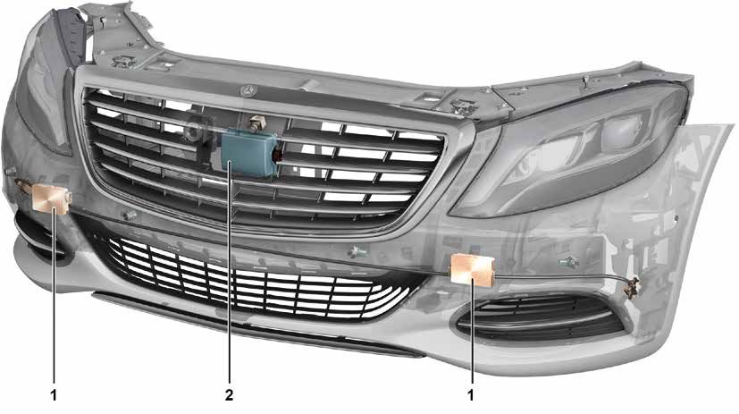
The reversing camera (RBC) from Mercedes-Benz switches Reversing camera version 2.0 (RVC 2.0) was extended with
on automatically when reverse gear or gear range "R" is trailer hitch mode. The picture displays a guide line for the
engaged and displays the area behind the vehicle on the CO- path of the trailer hitch (not with Audio 20) and is equipped
MAND display. It thus provides a better view of the immediate with optical and electrical distortion correction. The camera
surroundings at the rear of the vehicle and provides effective is located centrally, directly on the rear-end door handle and
assistance for parallel and perpendicular parking. has a special new dirt-resistant coating on the lens. Another
new feature is maneuvering mode whereby the camera re-
Different variants are in use depending on the model series. mains switched on in a forward gear for a defined period of
Reversing camera version 1.0 (RVC 1.0) displays only a pic- time or defined distance. Static guide lines are replaced by
ture without guide lines on the central display as soon as re- dynamic guide lines on the new version and show the path of
verse gear is engaged. The system uses an operating voltage the vehicle depending on the steering wheel angle. The PTS
of 5 V and requires an additional modulator (control unit). On indicator is also shown on the COMAND display (not with
certain model series (see table), the COMAND shows static Audio 20).
guide lines, or dynamic guide lines in BR 221 before MOPF.
In the case of version 3.0 (RVC 3.0), the reversing camera
has a direct digital connection to the COMAND and features
a 180-degree field of view as well as object recognition.
P54.33-3411-00 P54.33-3412-00
Display on instrument cluster for maneuvering mode Instrument cluster display for trailer mode (with code 550 Trailer hitch)
1 Virtual steering angle (dynamic, yellow guide lines) 3 Virtual steering angle (yellow guide line)
2 Virtual vehicle width (static, white guide lines) 5 "Trailer mode active" symbol
4 "Maneuvering mode active" symbol f Distance line around ball head (red guide line):
c Distance line 0.30 m
d Distance line 1.0 m
e Distance line 4.0 m
Driver Assistance Systems | Technology Guide 31Reversing camera
Parking systems
System limits
The camera does not detect any objects outside of the ca- bbService information
mera viewing cone. The function is limited or not available in The reversing camera with dynamic guide lines has to
the event of direct sunlight, heavy rain, fog or a concealed/ be calibrated after installation.
dirty lens.
Special tool for calibration for RVC 2.0
Components Order no.: 00058901210 (see Gotis)
• 1 x camera
• 1 x modulator with RVC 1.0 Automatic calibration with RVC 2.0 in model 207/212
• 1 x control unit with BR 221 before MOPF MOPF, C218 MY 2014 and RVC 3.0
Diagnosis
• RVC control unit
P54.33-3413-00 P54.65-5177-00
180° view Reversing camera on rear-end door handle
6 Parktronic indicator
32 Driver Assistance Systems | Technology GuideReversing camera
Parking systems
Overview of the individual reversing camera systems
Model series RVC 1.0 RVC 2.0 RVC 3.0
Dynamic guide lines Dynamic guide lines
C 117 X
164 X
164 MOPF X1
W/X 166 X
W 176 X
W/S/C 204 MOPF X
X 204 X1
X 204 MOPF X
A/C 207 X
A/C 207 MOPF X
W/S/V 212 X
W/S/V 212 MOPF X
C 216 MOPF X1
C 218 X
C 218 as of MY14 X
X 218 X
W/V 221 MOPF X1
W/V 222 X
R 231 X
W 246 X
251 X
251 MOPF X1
1 Static guide lines
Driver Assistance Systems | Technology Guide 33360° camera system
Parking systems
Features
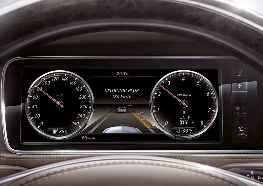
The 360° camera system from Mercedes-Benz receives The cameras are positioned in the radiator grille, in the out-
picture information from four cameras. The picture, which is side mirror housings and in the liftgate handle strip respec-
processed by an image processing system, appears on the tively. Based on the four camera images, the steering wheel
COMAND display in real time and displays a bird's eye view angle and stored vehicle parameters, the system calculates
of the vehicle and its surroundings. The vehicle corners and an artificial picture and displays this bird's eye view of the
sides are monitored with the aim of protecting the outside vehicle and its surroundings (3 m at front/rear and 2.5 m at
mirrors and rims. The display of cross-traffic at the front and side) on the Audio/COMAND display with guide lines. The
rear allows the driver to park, maneuver and exit areas safely. camera viewing angle is up to approx. 180° horizontally and
up to approx. 120° vertically.
P54.33-3414-00 P54.33-3415-00
View on instrument cluster View on instrument cluster
a Distance line 0.30 m
b Distance line 1.00 m
c Distance line 4.00 m
34 Driver Assistance Systems | Technology Guide360° camera system
Parking systems
System limits
The side cameras are shut off if the door is opened. Curb bbService information
edges may be shown in an offset position in the top view due After a camera is replaced, it must be calibrated du-
to their height profile. ring a calibration drive. If more than one camera is
replaced, all cameras have to be calibrated during a
Components calibration drive.
• 4 x camera
• 1 x 360° camera control unit After the control unit is replaced, the calibration va-
• RVC control unit lues from the old control unit can be transferred to
the new control unit using Xentry.
Diagnosis
• 360° camera system
P54.33-3416-00
360° view on instrument cluster
Driver Assistance Systems | Technology Guide 35Overview
Driving Safety Systems
Driving safety systems Abbrevia- SA code Model series
tion
Brake Assist System BAS Standard Standard as of BR 210
Brake Assist System (BAS BAS+ 233 166, 172, 204 MOPF, 207, 212, 216, 218, 221, 222, 231
PLUS) (on vehicles with DISTRONIC PLUS)
Adaptive Brake Assist - 239/ 117, 176, 246, 242, 207/212 MOPF, 222, 166 (as of MY
252/ 2013) (with code 239, 252 or 258)
258
Brake Assist System PLUS with BAS+Q 233 and 207/212 MOPF, 222
Intersection Assist 269
PRE-SAFE® brake CMS 233 CMS: 164, 251, 209, 230, 211, 219
CMS and CMS2: 207, 212, 221, 216, 204 MOPF, 166,
218, 231, 172
PRE-SAFE® PLUS - 253 207/212 MOPF, 222
COLLISION PREVENTION CPA 252/258 Code 252: 246, 176, 166 (as of MY 2013)
ASSIST Code 258: 207/212 MOPF, 222, 117
COLLISION PREVENTION CPA+ 239 117, 176/242/246 as of MY 2014
ASSIST PLUS
30 m
80 m
200 m
500 m
P54.70-2665-00
Detection ranges of radar sensors and stereo multifunction camera
Detection range of left and right front bumper short-range radar sensor Detection range of long-range radar sensor
Detection range of COLLISION PREVENTION ASSIST Detection range of stereo multifunction camera
36 Driver Assistance Systems | Technology GuideBrake Assist System (BAS/BAS PLUS)
Driving Safety Systems
Features BAS components
The Brake Assist System (BAS) from Mercedes-Benz imme- • Diaphragm travel sensor and release switch or
diately makes the maximum braking force available when the • pressure sensor in the hydraulic unit
brake pedal is depressed quickly and deliberately. The system
thus helps to prevent rear-end collisions or to reduce the im- BAS PLUS components
pact velocity. • Pressure sensor in the hydraulic unit
• 1 x long range radar
The extended functionality of the BAS PLUS Brake Assist • 2 x short-range radar sensors
System and Adaptive Brake Assist System provides situation- • 1 x steering angle sensor
dependent brake servo assistance with the help of the radar • 1 x radar control unit
sensor system. The system thus performs optimized and con-
trolled brake applications to fulfill the driver's request, all the Diagnosis
way up to emergency braking if necessary. • ESP control unit
• BAS control unit on BR 140, 202, 208, 210
System limits of BAS PLUS • Radar sensors control unit (SGR) (BAS PLUS)
The system operates in the vehicle speed range of 30 - 250
km/h for moving objects and 30 - 72 km/h for stationary
objects.
bbService information
See DISTRONIC PLUS
Driver Assistance Systems | Technology Guide 37You can also read