ELAD DUO-ART 120 HF/50MHz 120W amplifier - USER MANUAL - Eladit.com
←
→
Page content transcription
If your browser does not render page correctly, please read the page content below

ELAD DUO-ART 120
HF/50MHz 120W amplifier

  USER MANUAL

        www.eladit.com
ELAD DUO-ART 120                                                                                          User Manual - Rev. 1.7 - 02/2020

Contents
Revision History ...................................................................................................................................... 3
Supplied Accessories ............................................................................................................................... 3
1      Introduction .................................................................................................................................... 4
    1.1        Notice ...................................................................................................................................... 4
    1.2        Precautions ............................................................................................................................. 4
    1.3        Software and firmware versions ............................................................................................. 4
    1.4        Features .................................................................................................................................. 4
    1.5        Block Diagram ......................................................................................................................... 5
2      Panels Description........................................................................................................................... 6
    2.1        Front Panel Description .......................................................................................................... 6
    2.2        Rear Panel Description ............................................................................................................ 7
3      User Interface ................................................................................................................................. 9
    3.1        Menu Bar and Push-buttons ................................................................................................... 9
    3.2        Main Window........................................................................................................................ 10
       3.2.1          Overview ............................................................................................................................. 10
       3.2.2          Main Menu .......................................................................................................................... 11
       3.2.3          Views ................................................................................................................................... 12
       3.2.4          Tune Menu .......................................................................................................................... 14
       3.2.5          Setting Menu ....................................................................................................................... 17
       3.2.6          Messages ............................................................................................................................. 25
    3.3        Memory Bank Window ......................................................................................................... 28
    3.4        Information Window............................................................................................................. 31
Annex A - Technical Specifications........................................................................................................ 32
Annex B - DUO-ART 120 Connections ................................................................................................... 34
    FDMDUO Interface - Local Setup ...................................................................................................... 34
    FDMDUO Interface - Remote Setup.................................................................................................. 34
    Generic Interface .............................................................................................................................. 35
    FT-817 Interface ................................................................................................................................ 35
Annex C - Tune-up Procedure ............................................................................................................... 36
    Foreword........................................................................................................................................... 36
    Warning............................................................................................................................................. 36
    With the FDM-DUO Transceiver ....................................................................................................... 37
    With a Generic Transceiver ............................................................................................................... 37
Product Warranty ................................................................................................................................. 38
Declaration of Conformity (EC) ............................................................................................................. 39
FCC Certification.................................................................................................................................... 40

      © 2020 ELAD S.r.l. All rights reserved. No part of this document may be reproduced, published, used, disclosed or disseminated
           in any form or by any means, electronic, photocopying or otherwise, without prior written permission of ELAD S.r.l.                                       2
ELAD DUO-ART 120 User Manual - Rev. 1.7 - 02/2020
Revision History
Revision Date Description
Rev 1.0 04/2018 First version.
Rev 1.1 04/2018 Added Annex A - Technical Specifications.
Updated pictures.
Rev 1.2 05/2018 Added Annex B - DUO-ART 120 Connections.
Added Supplied Accessories section.
Rev 1.3 05/2018 Updated pictures.
Rev 1.4 06/2018 Updated Annex A - Technical Specifications.
Rev 1.5 07/2018 Added section 1.5 Block Diagram.
Updated section 2 Panels Description.
Updated section 3 User Interface.
Updated Annex B - DUO-ART 120 Connections.
Added Annex C - Tune-up Procedure.
Rev 1.6 08/2018 Updated section 1.3 Software and firmware versions.
Updated the menu items table under section 3.2.5 Setting
Menu.
Rev 1.7 02/2020 Various minor fixes.
Added information about the Stand-By mode in section 3.2.2
Main Menu.
Updated section 3.2.4 Tune Menu.
Updated the menu items table under section 3.2.5 Setting
Menu.
Added the description of menu 2 (Rx Filters Setting) and 40
(Spectrum Settings) at the end of section 3.2.5 Setting Menu.
Added the description of the Auto Tune Low Pwr warning.
Updated section 3.3 Memory Bank Window.
Updated section 3.4 Information Window.
Updated FT-817 Interface.
Updated Annex C - Tune-up Procedure.
Underlined and bolded the clickable links within the document.
Supplied Accessories
1 LAN cable.
1 PTT cable (jack 3.5 mm).
1 EXT I/O cable (DB9 connector type).
1 power cord (US or Schuko version).
2 PL-259 cables (for FDM-DUO RX and RTX connections).
1 DC power cord (Powerpole to 2.1 mm jack) to power the FDM-DUO.
1 user manual.
© 2020 ELAD S.r.l. All rights reserved. No part of this document may be reproduced, published, used, disclosed or disseminated
in any form or by any means, electronic, photocopying or otherwise, without prior written permission of ELAD S.r.l. 3
ELAD DUO-ART 120 User Manual - Rev. 1.7 - 02/2020
1 Introduction
1.1 Notice
Amateur radio regulations vary from country to country. Check local amateur radio regulations and
requirements before operating the ELAD DUO-ART 120.
1.2 Precautions
Connect the amplifier only to a power source described in this manual.
Take care when plugging-in cables, avoid applying sideways pressure that might damage the
connectors.
Avoid operating in wet conditions.
Leave an empty space of at least ten centimeters (10cm / 4in) on both sides of the amplifier
to allow the fans to operate correctly.
For better performance and safety, connect the amplifier to good earth ground using a
short, heavy, braided cable.
Ground all outdoor antennas for this amplifier using approved methods. Grounding helps
protect against voltage surges caused by lightning. It also reduces the chance of build-up of
static charge.
1.3 Software and firmware versions
The features described in this manual refers to the following versions :
User Interface software Internal firmware
Version 1.70 - date 11/20/2019 Version 1.02 – date 06/28/2018
1.4 Features
The DUO-ART 120 is a 120 watt amplifier for HF and 50MHz frequency ranges. It includes the
internal PA power supply, preselector filters, an antenna tuner (optional) and acts as remote
controller for the FDM-DUO.
The DUO-ART 120 has three modes of operation that are called interfaces :
1. FDMDUO interface : this interface is used when operating with the FDM-DUO,
2. Generic interface : this interface is used when operating with another transceiver,
3. FT-817 interface : this interface is used to read the frequency through the RS-232 port using
the FT-817 CAT protocol.
The DUO-ART 120 has 20 memory banks and each one saves :
1. the interface used,
2. the attenuators setting,
3. the antenna used,
4. the use of the antenna tuner,
5. and other settings.
The USA version of the DUO-ART 120 has a security feature that prevents to amplify in the frequency
band 26-28MHz. Any attempt to drive the amplifier in the 26-28MHz frequency band will result in
0dB gain from input to output of the amplifier.
© 2020 ELAD S.r.l. All rights reserved. No part of this document may be reproduced, published, used, disclosed or disseminated
in any form or by any means, electronic, photocopying or otherwise, without prior written permission of ELAD S.r.l. 4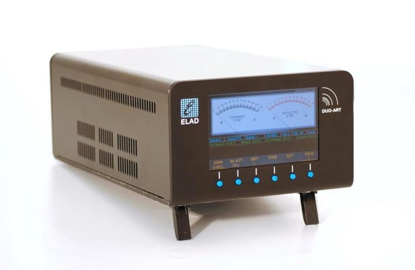
ELAD DUO-ART 120                                                                          User Manual - Rev. 1.7 - 02/2020

1.5 Block Diagram
The block diagram below shows the possible paths of the RF signal.

    © 2020 ELAD S.r.l. All rights reserved. No part of this document may be reproduced, published, used, disclosed or disseminated
         in any form or by any means, electronic, photocopying or otherwise, without prior written permission of ELAD S.r.l.         5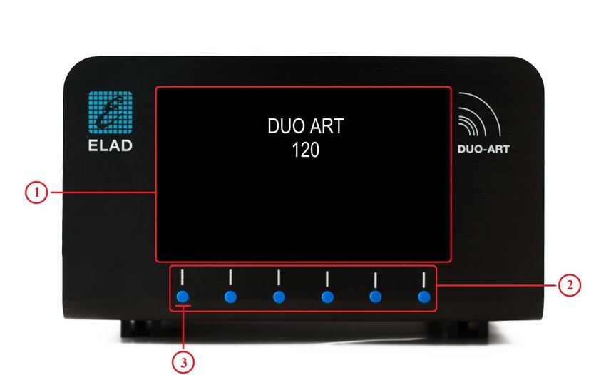
ELAD DUO-ART 120                                                                          User Manual - Rev. 1.7 - 02/2020

2 Panels Description
2.1 Front Panel Description

1 - Display
5.0 inches LCD TFT display with resolution of 800x480 pixels. Displays menus, power values and
amplifier status.

2 - Push-buttons
These six Push-buttons allow to navigate in the menus and change the various working modes.

3 - Power button
To powered up the amplifier, first switch the main power switch on the rear panel, then press the
first button on the left. When this button is released the amplifier emits an acoustic signal and in
about ten to twenty seconds it will be ready to operate.

 The menu 94 “Turn Off Hardware” allows to put the DUO-ART 120 in Low Power mode, stopping
 both the software and the firmware. To shut down completely the DUO-ART 120 use the power
 switch situated on the rear panel.

    © 2020 ELAD S.r.l. All rights reserved. No part of this document may be reproduced, published, used, disclosed or disseminated
         in any form or by any means, electronic, photocopying or otherwise, without prior written permission of ELAD S.r.l.         6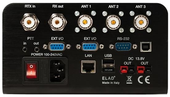
ELAD DUO-ART 120                                                                          User Manual - Rev. 1.7 - 02/2020

2.2 Rear Panel Description

1 - Main power supply
Power switch, fuse holder and 100-240Vac power supply connector. Insert the power supply cable
and use the power switch to power up the amplifier.

2/3 - PTT in/out
3.5mm jack connectors.
PTT in        Input for transmit control, connect TIP to ground to put the amplifier
              in transmit state.

PTT out       The TIP goes to ground while transmitting.

RING connection is not used.

4 - RTX connection
SO-239 connector. Transmit path with the FDMDUO interface. Reception and transmit paths with
the other interfaces (Generic and FT-817).

5 - RX connection
SO-239 connector. Reception path with the FDMDUO interface.

6 - Antennas
SO-239 connectors to connect up to three antennas.

    © 2020 ELAD S.r.l. All rights reserved. No part of this document may be reproduced, published, used, disclosed or disseminated
         in any form or by any means, electronic, photocopying or otherwise, without prior written permission of ELAD S.r.l.         7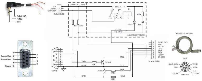
ELAD DUO-ART 120                                                                          User Manual - Rev. 1.7 - 02/2020

7 - RS-232 port
DB9 connector for the FT-817 interface acting on an RS-232 serial link.

8 - AUX USB port
Reserved for service.

9 - USB connection
USB type A female connectors for host type connections.

10 - Output power supply
Allows to power other devices without the need of other power units. Max 2A. Powerpole connector
type.

11 - LAN connection
RJ45 connector for LAN connection.

12 - EXT I/O
EXT I/O connection with external hardware such the FDM-DUO.

13 - Ground Connector
For better performance and safety, connect it to an earth ground using a short and wide cable.

 The DUO-ART 120 Output power Supply ⑩ can be used to power both the FDM-DUO and the
 ELAD SP-1A speaker.

    © 2020 ELAD S.r.l. All rights reserved. No part of this document may be reproduced, published, used, disclosed or disseminated
         in any form or by any means, electronic, photocopying or otherwise, without prior written permission of ELAD S.r.l.         8
ELAD DUO-ART 120 User Manual - Rev. 1.7 - 02/2020
3 User Interface
3.1 Menu Bar and Push-buttons
The Menu Bar is composed of six labels corresponding to the Push-buttons. It allows together with
the Push-buttons to modify the settings and navigate in the menus; therefore, the labels of the
Menu Bar change in function of the selected Window or Menu.
The picture below shows the Menu Bar with the Push-buttons when the Main Window is displayed.
The Push-buttons have two type of press :
a normal press,
and a long press.
Long press is available when the label is underlined, as seen in the picture above for the MEM
and VIEW labels. The settings menu 10 “Long Press Time” allows to modify the long press
duration.
Even if Push-buttons and labels are two separate things, this manual refers to a push-button
using its label.
For example : “press the SET button” stands for “press the button under the SET label”.
© 2020 ELAD S.r.l. All rights reserved. No part of this document may be reproduced, published, used, disclosed or disseminated
in any form or by any means, electronic, photocopying or otherwise, without prior written permission of ELAD S.r.l. 9
ELAD DUO-ART 120                                                                          User Manual - Rev. 1.7 - 02/2020

3.2 Main Window
3.2.1    Overview
When the DUO-ART 120 is started the Main Window is displayed. This window is divided in six
horizontal areas :
    1. the top one shows the device name, the date, the hour and information about the LAN
        connection,
    2. the second area shows a graph with the current transmission power and operating
        frequency, the          label is displayed when the DUO-ART 120 is in transmission state,
    3. the third area (text in blue) is a status bar that includes information about the current
        settings,
    4. the fourth area (text in green) is a diagnostic bar that shows some diagnostic information,
    5. the fifth area is used to show the warning and error Messages, some generic information
        (on the left) and the status of the antenna tuner (on the right),
    6. the last area is the Menu Bar which is composed of six labels corresponding to the six Push-
        buttons.

 The menu 30 “Powers Unit” allows to choose the unit of measurement used to display the
 powers on the Main Window, Watt or dBm.
 The menu 31 “Temperatures Unit” allows to choose the unit of measurement used to display
 the temperatures on the Main Window, Celsius or Fahrenheit.

    © 2020 ELAD S.r.l. All rights reserved. No part of this document may be reproduced, published, used, disclosed or disseminated
         in any form or by any means, electronic, photocopying or otherwise, without prior written permission of ELAD S.r.l.         10
ELAD DUO-ART 120 User Manual - Rev. 1.7 - 02/2020
3.2.2 Main Menu
The picture below shows the Menu Bar with the Push-buttons when the Main Window is displayed.
A normal press on the Push-buttons allows to perform the following operations :
MEM: switch between the memory banks where the configurations are saved.
IN-ATT: choose between the Stand-By mode and an Input Attenuators value (0, 2, 3 or 5
dB).
ANT: choose the antenna connector used to operate.
TUNE: allows to access to the Tune Menu.
SET: allows to access to the Setting Menu.
VIEW: switch between the different Views.
A long press on the Push-buttons allows to perform the following operations :
MEM: allows to access to the Memory Bank Window.
VIEW: allows to access to the Information Window.
The menu 1 “Max Banks Number” allows to modify the banks number in use until a maximum of
20 banks.
In Stand-By mode the internal PA (Power Amplifier) is not activated. The PA is activated when an
attenuator value is chosen (0dB, 2dB, 3dB or 5 dB).
Refer to section 1.5 Block Diagram to see where are the attenuators and the PA. The Stand-By
mode allows bypassing attenuators and PA.
© 2020 ELAD S.r.l. All rights reserved. No part of this document may be reproduced, published, used, disclosed or disseminated
in any form or by any means, electronic, photocopying or otherwise, without prior written permission of ELAD S.r.l. 11ELAD DUO-ART 120 User Manual - Rev. 1.7 - 02/2020
3.2.3 Views
While the Main Window is displayed, it is possible to switch the view with a normal press on the
VIEW button. The number under indicates the selected view.
VIEW 1 : forward power and reflected power.
VIEW 2 : forward power and SWR.
VIEW 3 : forward power and input power.
© 2020 ELAD S.r.l. All rights reserved. No part of this document may be reproduced, published, used, disclosed or disseminated
in any form or by any means, electronic, photocopying or otherwise, without prior written permission of ELAD S.r.l. 12ELAD DUO-ART 120 User Manual - Rev. 1.7 - 02/2020
VIEW 4 : spectrum view.
VIEW 5 : spectrum zoomed view.
Spectrum views are available only with the FDMDUO interface.
Menu 32 "View on TX" allows you to choose which view to display during transmission.
© 2020 ELAD S.r.l. All rights reserved. No part of this document may be reproduced, published, used, disclosed or disseminated
in any form or by any means, electronic, photocopying or otherwise, without prior written permission of ELAD S.r.l. 13ELAD DUO-ART 120 User Manual - Rev. 1.7 - 02/2020
3.2.4 Tune Menu
While the Main Window is displayed, it is possible to enter to the Tune Menu with a normal press
on the TUNE button. The tune menu allows, if the ATU (automatic antenna tuner) is installed, to
proceed to the tune-up procedure.
The picture below shows how changes the Main Window while the Tune Menu is displayed.
Button functionalities are the following :
- the BACK button allows to exit from the Tune Menu,
- the ATU button allows to enable and disable (to bypass) the ATU,
- the TUNE button allows to start the automatic tune-up which consists in carrying out a
coarse tune-up followed by a fine tune-up,
the ATU must be enabled with the ATU button in order to start the tune-up,
- the TUNE F button allows to proceed to a fine tune up,
this operation is valid only if a manual tune-up has been carried out first,
- the MANUAL Tune button allows to access to the manual tune menu.
The ATU state is saved in the selected Memory Bank, this state can be ON or ByPass. Tune-up
results are store in base of the selected bank and antenna.
To start the tune-up use the TUNE button. The DUO-ART 120 will first start a coarse tune-up and
after finding the best point it will perform an accurate tune-up.
When a tune-up is successful, the DUO-ART 120 saves the tuning data relating to :
- the selected memory bank,
- the selected antenna,
- the reference frequency.
This tuning data are automatically reloaded when the same working conditions occur again : same
bank, same antenna, same frequency.
© 2020 ELAD S.r.l. All rights reserved. No part of this document may be reproduced, published, used, disclosed or disseminated
in any form or by any means, electronic, photocopying or otherwise, without prior written permission of ELAD S.r.l. 14ELAD DUO-ART 120 User Manual - Rev. 1.7 - 02/2020
The ATU functioning depends on the memory banks organization. For each bank three sets of
tuning data are saved; one set for each antenna. A set of tuning data is nothing more than a list of
tuning data organized relatively to reference frequencies. The number of tuning data (in other
words the number of reference frequencies) depend on the step used according to the operating
band :
- for 160m the step is 2kHz,
- for 80m the step is 4kHz,
- for 60m the step is 5kHz,
- for 40m the step is 5kHz,
- for 30m the step is 10kHz,
- for 20m the step is 10kHz,
- for 17m the step is 10kHz,
- for 15m the step is 20kHz,
- for 12m the step is 25kHz,
- for 10m the step is 25kHz,
- for 6m the step is 50kHz.
Some practical examples of what happens :
- start tune-up with working frequency equal to 14.001MHz, the tuning data is saved on the
reference frequency 14.000MHz,
- start tune-up with working frequency equal to 14.002MHz, the previous tuning data on the
reference frequency 14.000MHz is overwritten by the new value,
- start tune-up with working frequency equal to 14.007MHz, the tuning data is saved on the
reference frequency 14.010MHz,
- the working frequency becomes equal to 14.002MHz, the tuning data of the reference
frequency 14.000MHz is loaded,
- the working frequency becomes equal to 14.009MHz, the tuning data of the reference
frequency 14.010MHz is loaded,
- the working frequency becomes equal to 14.011MHz, the tuning data of the reference
frequency 14.010MHz is kept loaded,
- the working frequency becomes equal to 14.016MHz, no tuning data is loaded.
The DUO-ART 120 displays messages on the right of the display to provide information on the loaded
and set tuning data. Messages can be :
- Tune Data Loaded : the tune-up has already been carried out and the data is in use, no tune-
up is needed (if the connected antenna has not been changed),
- No Tune Data Available : no tuning data was found and no data is therefore in use, it is
necessary to perform the tune-up,
- Antenna Tuner Bypassed : the tuner is in bypass, the bypass can be removed to check the
tune-up status, i.e. "Loaded" or "Not Available".
To tune-up antennas follow the tune-up procedure in Annex C - Tune-up Procedure.
© 2020 ELAD S.r.l. All rights reserved. No part of this document may be reproduced, published, used, disclosed or disseminated
in any form or by any means, electronic, photocopying or otherwise, without prior written permission of ELAD S.r.l. 15ELAD DUO-ART 120 User Manual - Rev. 1.7 - 02/2020
While the Tune Menu is displayed, it is possible to switch to the Manual Tune Menu with a normal
press on the MANUAL Tune button.
This menu allows you to manually adjust the various ATU parameters which are :
- the ATU configuration : by long pressing on the left button you can choose one of three
configurations : CL (first capacitance and after inductance), LC (first inductance and after
capacitance) and finally ByPass,
- the value of the inductance : the down L and up L buttons allow you to change the value,
- the capacity value : the down C and up C buttons allow you to change the value.
The StartTX button allows you to start the transmission in order to evaluate the effect of the current
configuration on the SWR, during transmission the StartTX button becomes the StopTX button
which is used to stop the transmission.
To save the manual tuning data you need to press the BACK button, the window changes and
another menu is presented:
- the ESC button allows you to exit without saving,
- the SAVE button allows you to save the current state of the ATU as a tuning data,
- the BANK and ANT buttons allow you to modify the destination for saving the tuning data if
necessary.
It is possible to proceed to a manual tune-up after performing an automatic tune-up to manually
adjust the tuning data.
© 2020 ELAD S.r.l. All rights reserved. No part of this document may be reproduced, published, used, disclosed or disseminated
in any form or by any means, electronic, photocopying or otherwise, without prior written permission of ELAD S.r.l. 16ELAD DUO-ART 120 User Manual - Rev. 1.7 - 02/2020
3.2.5 Setting Menu
While the Main Window is displayed, it is possible to enter to the Setting Menu with a normal press
on the SET button.
The picture below shows how changes the Main Window while the Setting Menu is displayed.
The BACK button allows to exit from the Setting Menu. The UP and DOWN buttons allow to
navigate in the Setting Menu.
The Setting Menu is organized in four columns that are the menu number, the menu group, the
menu name and the current value visualization.
To modify the value of an menu, press the ENTER button, use the - and + button to modify the value
and finally press ENTER.
© 2020 ELAD S.r.l. All rights reserved. No part of this document may be reproduced, published, used, disclosed or disseminated
in any form or by any means, electronic, photocopying or otherwise, without prior written permission of ELAD S.r.l. 17ELAD DUO-ART 120 User Manual - Rev. 1.7 - 02/2020
“Setting Menu” refers to the Setting Menu visualization, “menu” refers to the individual menu
items.
The following table presents all the available menu items. It is organized in three section : GENERAL, VISUALIZATION and ADVANCED.
# Menu Group Menu Name Menu Description Values Default
GENERAL SECTION
1 MEMORY BANKS Max Banks Number Sets the number of memory banks to use 2 to 20 3
2 FILTERS Reception Filters Setting Allows to enable/disable the reception filters ON / OFF OFF
For details see the section Menu 2: Rx Filters Setting after this table
5 MODALITY Use Mode Sets the DUO-ART modality Local / Remote Local
6 MODALITY Remote Password Allows to view the password and generate a new one Exit / Generate Exit
10 TIME Long Press Time Sets the time used to recognize a long press on the buttons 0.3 to 5.0 sec 0.5 sec
11 TIME Screensaver Timeout Specifies the screensaver timeout 5min / 10min / 20min / 30min / 10min
60min
15 PEAK POWER METER Activation Enables/disables the Peak Power Meter function on the Main ON / OFF OFF
Window
16 PEAK POWER METER Release Time Sets the release time of the Peak Power Meter function 0 to 5000 ms, in 10ms steps 3000 ms
20 TUNE Enable Tune Enables/disables the tune functionality ON / OFF ON
21 TUNE Force Attenuator Force a different attenuator value during tuning 0dB / 2dB / 3dB / 5dB 0dB
22 TUNE Target SWR (0=Off) Sets the SWR target value 0 / 1.00 to 10.00 in 0.01 steps 1.00
23 TUNE Auto Tune Timeout Sets the Auto Tune timeout 5 to 25 seconds in 5sec steps 5sec
24 TUNE ATU Installed Specifies if ATU is installed or not Yes / No Yes
25 TUNE Duo PttOut (menu 56) Allows to manage the PTT output of the FDM-DUO during tuning Force To No / Not Force Force To No
© 2020 ELAD S.r.l. All rights reserved. No part of this document may be reproduced, published, used, disclosed or disseminated
in any form or by any means, electronic, photocopying or otherwise, without prior written permission of ELAD S.r.l. 18ELAD DUO-ART 120 User Manual - Rev. 1.7 - 02/2020
# Menu Group Menu Name Menu Description Values Default
VISUALIZATION SECTION
30 MAIN WINDOW Powers Unit Specifies the unit used to display the powers on the Main Window Watt / dBm Watt
31 MAIN WINDOW Temperatures Unit Specifies the temperature unit to use in the Main Window Celsius / Fahrenheit Celsius /
Fahrenheit
32 MAIN WINDOW View on TX Allows to display a different view during transmission OFF / View 1 / View 2 / View 3 / OFF
View 4 / View 5
40 PLOT Spectrum Settings Allows to set for each band : Exit / Modify Exit
- the reference level (Ref Lev); -300 to 100 dBm (default -110dBm)
- the position of the reference (Ref Pos); 0 to 10 (default 0)
- the number of dBm per division (Point Div); 1, 2, 5, 10 or 20 (default
10)
- the offset value of the graph (Offset); -200 to 200 dBm (default
0dBm)
For details see the section Menu 40: Spectrum Settings after this
table
45 PLOT Waterfall Enable Enable or disable the display of the waterfall on views 4 and 5 ON / OFF OFF
46 PLOT Waterfall Position Allows to choose where to display the waterfall relative to the Top / Bottom Bottom
spectrum
47 PLOT Waterfall Scroll Allow to choose how the waterfall slides vertically, up or down Up / Down Up
48 PLOT Waterfall Max dBm Allows to set the upper limit of the waterfall display in dBm -200 a 200 dBm -40 dBm
49 PLOT Waterfall Min dBm Allows to set the lower waterfall display limit in dBm -200 a 200 dBm -140 dBm
© 2020 ELAD S.r.l. All rights reserved. No part of this document may be reproduced, published, used, disclosed or disseminated
in any form or by any means, electronic, photocopying or otherwise, without prior written permission of ELAD S.r.l. 19ELAD DUO-ART 120 User Manual - Rev. 1.7 - 02/2020
# Menu Group Menu Name Menu Description Values Default
ADVANCED SECTION
50 LAN IP IP address setting IP address -
example: 192.168.1.10
51 LAN Subnet Subnet setting Subnet mask -
example:255.255.255.0
52 LAN Gateway Gateway setting Default gateway -
example : 192.168.1.1
53 LAN DNS DNS setting DNS server -
example : 8.8.8.8
60 TEMPERATURE P1 Alarm Set Point Alarm threshold for sensor temperature 1 20°C to max allowed 70 °C
61 TEMPERATURE P2 Alarm Set Point Alarm threshold for sensor temperature 2 20°C to max allowed 70 °C
65 FAN CONTROL Work Mode Allows to choose between two working modes: Hi Perf or SSB Hi Perf
- Hi Perf: fan intensive use - SSB: fan reduced use
70 FREQ Period Frequency calculation period of the frequency meter 10 to 10000 ms, in 10ms steps 10 ms
90 SERVICE Factory Default Allows to reset the parameters to the factory default No Default / Set Default No Default
91 SERVICE Remote Service Enables remote connection for maintenance ON / OFF OFF
92 SERVICE Software Update (UI) Launches the software update (user interface) ON / OFF OFF
93 SERVICE Firmware Update Enables the firmware update (internal circuitry) ON / OFF OFF
94 SERVICE Turn off Hardware Allows to shut down the hardware ON / OFF OFF
© 2020 ELAD S.r.l. All rights reserved. No part of this document may be reproduced, published, used, disclosed or disseminated
in any form or by any means, electronic, photocopying or otherwise, without prior written permission of ELAD S.r.l. 20ELAD DUO-ART 120 User Manual - Rev. 1.7 - 02/2020
Menu 2 : Rx Filters Setting.
Choosing Modify in menu 2 Rx Filters Setting gives access to a window that presents the list of
settings for the reception filters, also called preselectors. These preselectors correspond to the
Preselector Filters part of the block diagram of section 1.5 Block Diagram.
Pressing the ENTER button after selecting the filter using the UP and DOWN buttons gives access to
another window that allows to change the frequency limits for activating the eight filters present in
the DUO-ART 120. It is also possible to deactivate and reactivate every single filter.
The NEXT button allows to change the selected field which is indicated in red. The STEP button
allows to choose the step with which to change the frequency values with the - and + buttons. The
SAVE button allows to save the changes made.
© 2020 ELAD S.r.l. All rights reserved. No part of this document may be reproduced, published, used, disclosed or disseminated
in any form or by any means, electronic, photocopying or otherwise, without prior written permission of ELAD S.r.l. 21ELAD DUO-ART 120 User Manual - Rev. 1.7 - 02/2020
After setting the frequency limits for each reception filter, the corresponding filter must be inserted
in the related slot. To do this, first remove the cover of the DUO-ART 120 by following these
instructions :
- turn off the DUO-ART 120 and disconnect all cables,
- turn the DUO-ART 120 upside down,
- remove the four cover fixing screws, as shown in the image below,
- turn the DUO-ART 120 over and remove the cover.
The image below indicates the number of the reception filter slots, relatively to what is written on
the FILTER SETTINGS screen.
Once the reception filters are inserted in their slots, close the DUO-ART 120.
© 2020 ELAD S.r.l. All rights reserved. No part of this document may be reproduced, published, used, disclosed or disseminated
in any form or by any means, electronic, photocopying or otherwise, without prior written permission of ELAD S.r.l. 22ELAD DUO-ART 120 User Manual - Rev. 1.7 - 02/2020
Menu 40 : Spectrum Settings.
Choosing Modify in menu 40 Spectrum Settings gives access to a window that shows the different
spectrum settings for each amateur band :
- Offset : is the offset value of the graph,
settable values are from -200dBm to + 200dBm, the default value is 0dBm,
- Lev : is the reference level,
settable values are from -300dBm to + 100dBm, the default value is -110dBm,
- Pos : is the position of the reference,
settable values are from 0 to 10, the default value is 0,
- Div : is the number of dBm per division,
settable values are 1, 2, 5, 10 or 20, the default value is 10.
The SET Default button allows to set the default values for all settings. The TYPE button (with the
choices Single or All) allows to choose whether to change the settings "row by row" (i.e. for each
amateur band) or then to change the settings for all amateur bands.
To choose the row (or amateur band) to be modified, use the UP and DOWN buttons, then press the
ENTER button to go to the next window which allows to change the various settings.
© 2020 ELAD S.r.l. All rights reserved. No part of this document may be reproduced, published, used, disclosed or disseminated
in any form or by any means, electronic, photocopying or otherwise, without prior written permission of ELAD S.r.l. 23ELAD DUO-ART 120 User Manual - Rev. 1.7 - 02/2020
This window allows to change the various spectrum settings.
The NEXT button allows to change the selected field which is indicated in red. The - and + buttons
allow to change the value of the selected field. The SAVE button allows to save the changes made.
© 2020 ELAD S.r.l. All rights reserved. No part of this document may be reproduced, published, used, disclosed or disseminated
in any form or by any means, electronic, photocopying or otherwise, without prior written permission of ELAD S.r.l. 24ELAD DUO-ART 120 User Manual - Rev. 1.7 - 02/2020
3.2.6 Messages
This section provides the list of messages that can be viewed on the DUO-ART 120 amplifier display.
There are two types of messages : warning and error. They are displayed in the lower right corner of
the display. The image below shows the position of the message and which button to press to reset
the warning or error. More than one message may appear in the same time on the display. It is
necessary to reset the messages with the reset button before using again the DUO-ART 120
amplifier.
The following table provides the list of all messages with their description.
Name Type Code Description
No LAN
Warning W-100 -
warning
Web socket
Warning W-101 -
warning
The DUO-ART 120 cannot find the sound card of the
Audio
Warning W-115 FDM-DUO. This warning is only displayed if the REMOTE
not found mode is active.
Problem with receiving audio coming from the FDM-
Audio read
Warning W-116 DUO. This warning is only displayed if the REMOTE
warning mode is active.
Audio write Problem of audio transmission to the FDM-DUO. This
Warning W-117
warning warning is only displayed if the REMOTE mode is active.
DUO mode The DUO-ART 120 is in REMOTE mode but the active
Warning W-130
not activated interface is not FDMDUO.
DUO EXTIO Reporting a communication problem between the DUO-
Warning W-131
warning ART 120 and the FDM-DUO.
© 2020 ELAD S.r.l. All rights reserved. No part of this document may be reproduced, published, used, disclosed or disseminated
in any form or by any means, electronic, photocopying or otherwise, without prior written permission of ELAD S.r.l. 25ELAD DUO-ART 120 User Manual - Rev. 1.7 - 02/2020
Name Type Code Description
Indicates an internal communication problem. After
Comm
Warning W-145 "warn" a code composed of alphanumeric characters is
warn added.
Indicates an internal problem of the operation of the
Micro Reset
Warning W-146 DUO-ART 120. This problem resolves automatically.
warning Warning code: ST-P10-b3.
CMD not
Warning W-147 Indicates the inability to perform an internal operation.
available
Automatic activation of the stand-by following an
Band warn
Warning W-148 unauthorized transmission.
StBy Warning code: ST-P10-b2.
This warning appears when the maximum time
Auto Tune available for automatic tuning of the antenna expires.
Warning W-160
timeout This time can be set from the "AutoTune Timeout"
menu.
This warning appears if the target SWR has not been
Auto Tune reached after the time-out has been set. This warning is
Warning W-161
SWR warning only displayed if the "Target SWR" menu is set to a
value other than 0.
The FDM-DUO has left the tuning mode (Tune) before
Auto Tune the DUO-ART 120. This warning is displayed if the
Warning W-162
DUO aborts tuning mode of the FDM-DUO times out or if the FDM-
DUO detects a high SWR.
Auto Tune This warning appears if the DUO-ART 120 has found a
Warning W-163
Max SWR tuning point but the calculated SWR is too high.
This warning appears if the DUO-ART 120 cannot
Auto Tune
Warning W-164 initiate the tune procedure because the input power is
Low Pwr too low.
High
Warning W-175 High temperature warning.
temperature
Maximum temperature exceeded. This error cannot be
High
Error E-400 reset. It is necessary to wait for the temperature to
temperature decrease before use the DUO-ART 120 amplifier again.
Error generated by a too high SWR. This is a hardware
HI SWR
Error E-410 protection.
error Error code: ST-P2-b1.
The current absorbed by the DUO-ART 120 has
Error
Error E-420 exceeded the maximum threshold.
I OUT Error code: ST-P9-b0.
© 2020 ELAD S.r.l. All rights reserved. No part of this document may be reproduced, published, used, disclosed or disseminated
in any form or by any means, electronic, photocopying or otherwise, without prior written permission of ELAD S.r.l. 26ELAD DUO-ART 120 User Manual - Rev. 1.7 - 02/2020
Name Type Code Description
The calculated reflected power has exceeded the
Error
Error E-421 maximum threshold.
REFL Error code: ST-P9-b1.
The calculated forward power has exceeded the
Error
Error E-422 maximum threshold.
FWD Error code: ST-P9-b2.
The input power of the DUO-ART 120 has exceeded the
Error
Error E-423 maximum threshold.
SENS PW Error code: ST-P9-b3.
Set filter selection error. This error is generally due to
Error
Error E-440 an incorrect frequency setting.
FILTER TX Error code: ST-P10-b0.
Error regarding the input power of the amplifier. The
PWR IN input power may be too high or the PTT input may not
Error E-441
error be connected properly.
Error code: ST-P10-b1.
Messages are not shown if the Memory Bank Window or the Information Window is displayed.
© 2020 ELAD S.r.l. All rights reserved. No part of this document may be reproduced, published, used, disclosed or disseminated
in any form or by any means, electronic, photocopying or otherwise, without prior written permission of ELAD S.r.l. 27ELAD DUO-ART 120 User Manual - Rev. 1.7 - 02/2020
3.3 Memory Bank Window
When the Main Window is displayed, doing a long press on the MEM button opens the Memory
Bank Window that contains all the settings which can be personalized for the selected banks.
Before to open the Memory Bank Window from the Main Window, check the selected bank
number.
For example : if the button label shows the Memory Bank Window will show the
bank 3 settings.
Below is an example of the Memory Bank Window.
On the top of the Memory Bank Window, the number of the selected bank and the associated
interface are shown. The center area of the window regroups the bands settings, for each band it is
possible to set :
PwrIn : the transmission power of the FDM-DUO (available only with the FDMDUO
interface),
Att : the attenuators value (0dB, 2dB, 3dB o 5dB) located before the PA (power amplifier),
AmpEnable : the internal power amplifier (PA) state, which can be On or Off (StdBy),
Ant : the selected antenna to transmit,
Atu : the enable state of the antenna tuner (ATU).
AmpEnable equal to Off (StdBy) corresponds to the Stand-By mode activated.
© 2020 ELAD S.r.l. All rights reserved. No part of this document may be reproduced, published, used, disclosed or disseminated
in any form or by any means, electronic, photocopying or otherwise, without prior written permission of ELAD S.r.l. 28ELAD DUO-ART 120 User Manual - Rev. 1.7 - 02/2020
These settings can be found :
in the Main Window where there are settings Att and AmpEnable (IN-ATT) and Ant (ANT):
in the Tune Menu where there is the setting Atu (ATU) :
DUO-ART 120 settings present in the Memory Bank Window are updated if modified from the
Main Window (Att, AmpEnable and Ant) or from the Tune Menu (Atu), this is true for the band
currently in use.
The INTERF button allows to choose the selected interface for the current memory bank. The UP and
DOWN buttons allow to select a band, once selected press on the ENTER button to modify the band
settings.
The UTIL button allows to access to the utilities functions (copy bank, reset bank, …).
A long press on the PWROFF button allows to power off the DUO-ART 120.
© 2020 ELAD S.r.l. All rights reserved. No part of this document may be reproduced, published, used, disclosed or disseminated
in any form or by any means, electronic, photocopying or otherwise, without prior written permission of ELAD S.r.l. 29ELAD DUO-ART 120 User Manual - Rev. 1.7 - 02/2020
The settings change window is as below. < and > keys allow you to change the selected field which is
indicated in red. - and + keys allow you to change the value of the selected field. The SAVE key
allows you to save the changes made.
© 2020 ELAD S.r.l. All rights reserved. No part of this document may be reproduced, published, used, disclosed or disseminated
in any form or by any means, electronic, photocopying or otherwise, without prior written permission of ELAD S.r.l. 30ELAD DUO-ART 120 User Manual - Rev. 1.7 - 02/2020
3.4 Information Window
When the Main Window is displayed, doing a long press on the VIEW button opens the Information
Window which displays some information about the DUO-ART 120 amplifier.
You can check here the software and firmware versions, as well as the current IP address.
A long press on the PWROFF button allows to power off the DUO-ART 120.
© 2020 ELAD S.r.l. All rights reserved. No part of this document may be reproduced, published, used, disclosed or disseminated
in any form or by any means, electronic, photocopying or otherwise, without prior written permission of ELAD S.r.l. 31ELAD DUO-ART 120 User Manual - Rev. 1.7 - 02/2020
Annex A - Technical Specifications
100 – 240 Vac 50/60Hz
AC Power Supply 2.3A (115V)
1.2A (230V)
1.8 – 30 MHz, 50 – 54 MHz
Frequency Range
Not allowed 26 – 28 MHz (USA version)
160m -> 1.800 – 2.000 MHz
80m -> 3.500 – 4.000 MHz
60m -> 5.3305 – 5.4035 MHz
40m -> 7.000 – 7.300 MHz
30m -> 10.100 – 10.150 MHz
Optimized Frequency Band 20m -> 14.000 – 14.350 MHz
17m -> 18.068 – 18.168 MHz
15m -> 21.000 – 21.450 MHz
12m -> 24.890 – 24.990 MHz
10m -> 28.000 – 29.700 MHz
6m -> 50.000 – 54.000 MHz
Typical 5W for 120W output (HF)
Input Power
10W maximum
Power Gain Less than 15 dB, 14dB typical
Typical 100W with 5W input (160m band)
Output Power Typical 120W with 5W input (80-10m band)
Typical 100W with 5W input (6m band)
> 50 dBc in HF band typical 60 dBc
Output Harmonic / Spurious Distortion
> 65 dBc in 6m band typical 68 dBc
Input Power
Output Power
VSWR
Metering
Drain Current
Drain Voltage
Temperature
© 2020 ELAD S.r.l. All rights reserved. No part of this document may be reproduced, published, used, disclosed or disseminated
in any form or by any means, electronic, photocopying or otherwise, without prior written permission of ELAD S.r.l. 32ELAD DUO-ART 120 User Manual - Rev. 1.7 - 02/2020
RTX Connector (SO239)
RX Connector (SO239)
Antenna Connector 1 (SO239)
Antenna Connector 2 (SO239)
Antenna Connector 3 (SO239)
Ground Connector
PTT Input Connector (jack 3.5 mm)
PTT Output Connector (jack 3.5 mm)
EXT IO1 Connector
Ports
EXT IO2 Connector
RS233 Connector
USB Connector (AUX)
LAN Connector
USB host1
USB host2
AC Power In Connector
DC OUT1 Connector (Powerpole)
DC OUT2 Connector (Powerpole)
1100 mm x 1800 mm x 3150 mm
Dimensions (H x W x L)
4,3 in x 7,1 in x 12,4 in
5 Kg
Weight
11 lb
© 2020 ELAD S.r.l. All rights reserved. No part of this document may be reproduced, published, used, disclosed or disseminated
in any form or by any means, electronic, photocopying or otherwise, without prior written permission of ELAD S.r.l. 33ELAD DUO-ART 120 User Manual - Rev. 1.7 - 02/2020
Annex B - DUO-ART 120 Connections
FDMDUO Interface - Local Setup
ANTENNAS
DUO-ART 120
FDM-DUO
FDMDUO Interface - Remote Setup
ANTENNAS
DUO-ART 120
FDM-DUO
USB HUB
ETHERNET ROUTER
© 2020 ELAD S.r.l. All rights reserved. No part of this document may be reproduced, published, used, disclosed or disseminated
in any form or by any means, electronic, photocopying or otherwise, without prior written permission of ELAD S.r.l. 34ELAD DUO-ART 120 User Manual - Rev. 1.7 - 02/2020
Generic Interface
ANTENNAS
DUO-ART 120
GENERIC TRANSCEIVER
FT-817 Interface
ANTENNAS
DUO-ART 120
FT-817 TRANSCEIVER
Interface Cable
Interface Cable Diagram
© 2020 ELAD S.r.l. All rights reserved. No part of this document may be reproduced, published, used, disclosed or disseminated
in any form or by any means, electronic, photocopying or otherwise, without prior written permission of ELAD S.r.l. 35ELAD DUO-ART 120 User Manual - Rev. 1.7 - 02/2020
Annex C - Tune-up Procedure
Foreword
To ensure maximum efficiency and RF output power it is important to have a good match from
power amplifier and antenna, the DUO-ART 120 is made to match nominally resistive 50 Ohm
impedance.
DUO-ART 120 can have the automatic antenna tuner unit (ATU) installed. The ATU is an hardware
option and can handle load mismatches.
When no ATU is installed there is no tune-up procedure because the DUO-ART 120 is factory aligned
for 50Ohm load, and allow to operate with a VSWR inferior to 2 at maximum power. The DUO-ART
120 safety conditions correspond to have 6W maximum of reflected power otherwise the DUO-ART
120 switches in Stand-By mode automatically (no gain).
When the ATU is installed, before operating in transmission it is recommended to make the tune
procedure for all antennas, bands and sub-bands. Tuning data are stored in memory bank, so when
the tune procedure is done data of ATU settings are automatically recalled based on the selected
antenna and the operating frequency. The DUO-ART 120 can save and manage up to 20 different
Memory Banks.
Warning
It is possible to bypass the DUO-ART 120 internal tuner and use an external tuner but it is mandatory
to exclude the internal one. Never use the internal tuner with an external tuner this can cause
damaging in DUO-ART 120.
© 2020 ELAD S.r.l. All rights reserved. No part of this document may be reproduced, published, used, disclosed or disseminated
in any form or by any means, electronic, photocopying or otherwise, without prior written permission of ELAD S.r.l. 36ELAD DUO-ART 120 User Manual - Rev. 1.7 - 02/2020
With the FDM-DUO Transceiver
When the DUO-ART 120 is connected to the FDM-DUO transceiver (with RTX coax cable, PTT jack
cable, EXT I/O flat cable and DC power cable), it is highly recommended to have this settings :
- DUO-ART 120 Interface selected : FDMDUO,
- FDM-DUO menu 49 TUNE TIME : 60 seconds,
- FDM-DUO menu 55 TUNE PWR : 5 watt,
- FDM-DUO menu 56 TUNE PTT : no.
These settings allow to make tuning without powering the PA, consequently the ATU is used safely,
with low power.
The tune-up procedure can be starting from both the FDM-DUO and the DUO-ART 120.
To start the procedure from the FDM-DUO :
- enter to the Tune Menu of the DUO-ART 120 and set the ATU to ON,
- press the F3 button on the FDM-DUO and the DUO-ART 120 will start the automatic tune-
up.
To start the procedure from the DUO-ART 120:
- enter to the Tune Menu of the DUO-ART 120 and set the ATU to ON,
- press the TUNE button to start the automatic tune-up.
If tune-up operation ends correctly (no Messages), data of the optimal matching are saved in the
selected bank. If needed, it is possible to proceed to a manual tune-up accessing to the MANUAL
Tune menu where inductance and capacitance can be adjusted manually.
With a Generic Transceiver
When the DUO-ART 120 is connected to a generic transceiver the frequency counter detects the
operating band and sub-band. To make the right tuning with the DUO-ART 120 ATU follow these
steps:
- set the output power of the transceiver at about 1W,
- set the transceiver to transmit a continuous tone (CW or FM),
- set the attenuators of the DUO-ART 120 at 0dB,
- enter to the Tune Menu of the DUO-ART 120 and set the ATU to ON,
- then, assert the PTT input of the DUO-ART 120,
- next, in the Tune Menu press the TUNE button to start the automatic tune-up.
If tune-up operation ends correctly (no Messages), data of the optimal matching are saved in the
selected bank. If needed, it is possible to proceed to a manual tune-up accessing to the MANUAL
Tune menu where inductance and capacitance can be adjusted manually.
© 2020 ELAD S.r.l. All rights reserved. No part of this document may be reproduced, published, used, disclosed or disseminated
in any form or by any means, electronic, photocopying or otherwise, without prior written permission of ELAD S.r.l. 37ELAD DUO-ART 120 User Manual - Rev. 1.7 - 02/2020
Product Warranty
ELAD S.r.l. warrants the DUO-ART 120 for a period of 2 years inside Europe, and for a period of 1
year outside Europe unless otherwise specified. Warranty begins from the purchase date. All DUO-
ART 120 will be repaired or replaced due to malfunction resulting from no fault of the end user. This
warranty covers normal intended usage of the product and does not cover misuse, abuse, accidents,
viruses, unauthorized service parts or the combination of other unauthorized branded products used
in conjunction with the DUO-ART 120.
© 2020 ELAD S.r.l. All rights reserved. No part of this document may be reproduced, published, used, disclosed or disseminated
in any form or by any means, electronic, photocopying or otherwise, without prior written permission of ELAD S.r.l. 38ELAD DUO-ART 120 User Manual - Rev. 1.7 - 02/2020
Declaration of Conformity (EC)
The product marked as
DUO-ART 120
manufactured by
Manufacturer: ELAD S.r.l.
Address: Via Col De Rust, 11 - Sarone
33070 CANEVA (PN)
is produced in conformity to the requirements contained in the following EC directives:
RED Directive 2014/53/CE
EMC Directive 2004/108/CE
Low Voltage Directive 2006/95/CE
RoHS Directive 2011/65/CE
The product conforms to the following Product Specifications:
Emissions & Immunity:
ETSI EN 301 489-1 V1.9.2
ETSI EN 301 489-15 V1.2.1
ETSI EN 301 783-2 V1.2.1
Safety:
EN 60950-1:2006 + A11:2009 + A1:2010 + A12:2011 + A2:2013
And further amendments.
This declaration is under responsibility of the manufacturer:
ELAD S.r.l.
Via Col De Rust, 11 - Sarone
33070 CANEVA (PN)
Issued by:
Name: Franco Milan
Function: President of ELAD
th
Caneva May, 4 2018
Place Date Signature
© 2020 ELAD S.r.l. All rights reserved. No part of this document may be reproduced, published, used, disclosed or disseminated
in any form or by any means, electronic, photocopying or otherwise, without prior written permission of ELAD S.r.l. 39ELAD DUO-ART 120 User Manual - Rev. 1.7 - 02/2020
FCC Certification
© 2020 ELAD S.r.l. All rights reserved. No part of this document may be reproduced, published, used, disclosed or disseminated
in any form or by any means, electronic, photocopying or otherwise, without prior written permission of ELAD S.r.l. 40You can also read


