Embedded Corrosion Instrument Model ECI-2 Product Manual
←
→
Page content transcription
If your browser does not render page correctly, please read the page content below

Embedded Corrosion Instrument
        Model ECI-2
      Product Manual

         Virginia Technologies Inc.
        660 Hunters Place, Suite 102
         Charlottesville, VA 22911
          Phone: (434) 970-2200
            Fax: (434) 817-6170
         www.vatechnologies.com

    Rev. 1.2, June 24, 2013 Virginia Technologies, Inc.
  Embedded Corrosion Instrument (ECI-2) Product Manual
Table of Contents
                                                            Page:

Introduction                                                        3

Theory of Operation                                                 4

Specifications                                                      7

Communications                                                      8

Verification and Testing                                            11

Installation                                                        12

Storage and Handling                                                15

Warranty                                                            15

Finite Element Analysis for Structural Integrity                    16

                                                   2
Embedded Corrosion Instrument (ECI-2) Product Manual

1.0 Introduction

1.1 Corrosion Monitoring of Steel Reinforced Concrete Structures Using Embedded Instrumentation

The ECI-2 is an embeddable non-destructive evaluation (NDE) corrosion-monitoring instrument. It is
capable of measuring parameters important to long term corrosion monitoring including linear
polarization resistance (LPR), open circuit potential (OCP), resistivity, chloride ion concentration ([Cl-]) and
temperature. Each ECI-2 instrument is a digital peripheral device connected on an embedded local area
network. The instruments communicate with an external datalogger using the SDI-12 industry standard
protocol. The information stored in the datalogger can be downloaded to a portable PC on site or
remotely using a wireless cellular connection, satellite connection, or phone line.

The ECI-2 has many applications in the construction and maintenance of commercial and civil structures.
Such structures can include, but are not limited to, high rise buildings, parking garages, bridges, dams,
spillways, flood control channels, piers, pylons and erosion control structures. Once the ECI-2 instrument
is properly embedded in the completed structure, long term monitoring of corrosive conditions can
proceed.

1.2 The Industrial Challenge
Civil structures such as bridges and dams are extremely large construction efforts, costing millions to
billions of dollars and spanning several years. In the United States alone, repairs for corrosion damage to
federal bridges are estimated at $50 billion annually. These structures are vital to commerce and the
standard of living of millions of people in the United States and billions of people worldwide. Worldwide
estimates to repair reinforced concrete structures are $200/m2 of exposed surface. Premature or
unexpected failures of these structures are often catastrophic in terms of time, money and lives. The high
costs of corrosion due to replacement and premature failures mandate the need for integrated in-situ
NDE systems. These NDE systems will provide information based on changes in the structure's corrosion
condition in order to affect timely maintenance interventions.

1.3 The Traditional Solution
Prior to the ECI-2, corrosion monitoring in steel reinforced structures has been conducted either by taking
concrete core samples from the structure, or by using embeddable probes. The core sampling technique
has the disadvantages of damaging the structure, temporarily disrupting traffic flow and other functions of
the structure, as well as being labor intensive with some safety risk to the sampling technician. The
embeddable probe technique is less invasive; it measures analog signals that can be interrogated using
electronic devices external to the structure. However, since the signals produced by these probes are
small in amplitude, they are subject to corruption from nearby electro-magnetic interference (EMI)
sources such as power lines, radios, cell phones and therefore must have limited lead lengths.

1.4 The VTI Solution
To address these disadvantages and limitations, VTI has developed a fully embeddable non-destructive
corrosion monitoring instrument that incorporates all required electrodes and signal processing

                                                       3
electronics. The ECI-2 approach allows the leads connecting the low-level analog signals to signal
processing electronics to be kept short (approximately 1 inch). Short analog signal leads allow for a higher
signal to noise ratio and more accurate and repeatable measurements. The ECI-2 communicates with
other instruments and an external datalogger using a digital protocol, which is highly resistant to
corruption from nearby EMI sources. SDI-12 compatible dataloggers and accessories are available from
Campbell Scientific, Inc.

1.5 Advantages of the ECI-2
The ECI-2 embeddable corrosion instrument incorporates 5 sensors into one small, rugged package that
can be easily installed and placed wherever needed to provide adequate coverage of a structure during
construction. The instruments are modular and uniquely addressable allowing the system to be easily
scaled to the needs of the specific structure. The ECI-2 is less susceptible to EMI than other corrosion
probes on the market by virtue of its extremely small lead lengths. Many embedded corrosion probing
systems rely on external electronics to drive (stimulate) the embedded probes and to measure the
resulting signals. Often these measurements have to be made over cables of 10 meters or more in length
which can act as antennas for EMI sources such as power lines, cell phones and radio waves. The leads
between the electrodes and data acquisition electronics in the ECI-2 are only about 1 inch in length and
are converted to digital data right at the source. The data is transmitted over a digital network, which is
relatively immune to interference.

ECI attributes include:
• Non-Destructive technique
• Measures several pertinent corrosion related parameters
• Contains all required electrodes and electronics
• Serves as a digital network peripheral device
• Digital data is resistant to corruption from nearby EMI sources
• Uses the industry standard SDI-12 protocol
• Each network connection can be up to 200 feet in length
• System can be powered using optional solar collector and rechargeable battery
• Wireless communication provided via an external cellular transceiver

2.0 Theory of Operation

2.1 Operational Principle
The ECI-2 monitors five parameters related to corrosion of reinforcement steel in concrete structures:
        1) Linear Polarization Resistance (LPR): LPR, measured in KΩ-cm2, is basically a resistance
        measurement of the interface between the sacrificial working electrode and the surrounding
        concrete. It is the measurement that is most closely related to the "corrosion rate" (typically
        measured in mm/yr.) of the reinforcement steel. The LPR measurement uses the black steel
        working electrode which corrodes at the same rate as black steel reinforcement rod. Note that if
        epoxy coated rebar is used as reinforcement steel in the structure, the ECI-2 working electrode
        may corrode at a higher rate than the epoxy coated steel. Even when epoxy coated rebar is used
        the ECI-2 LPR measurement is still useful as a measurement of the corrosion rate trend indicator
        (stable, reduced, elevated). The ECI-2 measures the corrosive nature of the embedded

                                                     4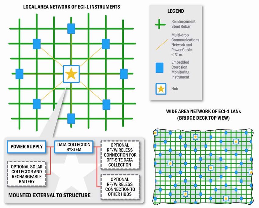
environment surrounding the instrument, rather than the corrosion rate of the structural steel
itself.

The LPR measurement is accomplished using the ECI-2 sacrificial black steel working electrode,
stainless steel counter electrode and Manganese Dioxide (MnO2) reference electrode. The
stainless steel counter electrode should last indefinitely. Although the manufacturer of the MnO2
reference electrode will not state its exact useful lifespan, these electrodes are known in
electrochemistry to be the most reliable and longest lived electrodes to use as references in
concrete.

2) Resistivity: Resistivity, measured in KΩ-cm, (or 1/conductivity) is used as an indicator of the
moisture content of the concrete. For corrosion to take place, the concrete must contain moisture
and chloride. The ECI-2 uses four stainless steel wire electrodes to accomplish resistivity
measurements. The stainless steel resistivity electrodes should last indefinitely.

3) Open Circuit Potential (OCP): OCP, measured in volts, is the electrochemical potential between
the sacrificial black steel working electrode and the MnO2 reference electrode. As corrosion rate
increases OCP typically becomes more negative. Similar to the LPR measurement, the ECI-2
accomplishes OCP measurements using sacrificial black steel working electrode and a MnO2
reference electrode. Although the manufacturer of the MnO2 reference electrode will not state its
exact useful lifespan, these electrodes are known in electrochemistry to be the most reliable and
longest lived electrodes to use as references in concrete.

4) Temperature: Temperature is measured in degrees Celsius. The ECI-2 accomplishes
temperature measurements using an internal semiconductor temperature sensor. This sensor
should last indefinitely.

5) Chloride Level: Chloride level is currently measured in Volts. As concrete chloride concentration
increases, this voltage becomes more highly negative. ECI-2 accomplishes chloride level
measurements by measuring the potential between an ion specific Silver/Silver Chloride (Ag/AgCl)
wire electrode and the instrument's MnO2 reference electrode. Again, these electrodes are known
to be the most reliable and longest lived electrodes to use as references in concrete.

The use of Ag/AgCl ion specific electrodes is the traditional and most straight forward approach
currently known in electrochemistry for measuring chloride concentration in concrete.
Unfortunately, these electrodes only have a limited useful lifespan. Research continues in this
area as alternative materials, including specialized polymers, are being investigated as possible
candidates for the construction of longer life chloride ion sensing electrodes.

Because of the lifespan limitation of its Ag/AgCl ion specific electrode the chloride level
measurement function of the ECI-2 is not intended to operate over the entire lifespan of a
structure. However, this function is useful as an early stage indicator of bad workmanship such as
a chloride contaminated concrete mixture during construction. It also has merit as a trend

                                             5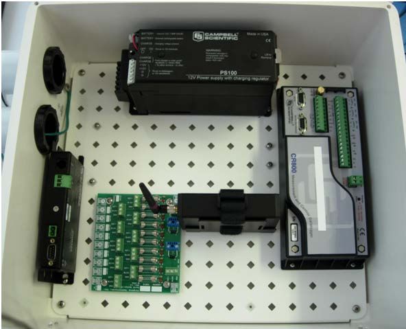
indicator of relative changes in chloride ion concentration (~ 59 mV / decade). However, changes
        in in-situ humidity may cause errors affecting both the scope and offset of these readings.

        6) Linear Correlation Coefficients (R value) for LPR and Resistivity Measurements: Linear
        Polarization measurements and Resistivity measurements are scanned measurements and collect
        a range of data points which are fitted using a linear regression algorithm. The quantity R, referred
        to as the linear correlation coefficient, measures the strength and the direction of a linear
        relationship between two variables. The value of R is reported between -1 and +1. An R value
        close to +1 indicates a strong positive linear correlation while an R value of +1 indicates a perfect
        positive fit. An R value close to -1 indicates a strong negative linear correlation while an R value of
        -1 indicates a perfect negative fit. The linear correlation coefficients are reported to give an
        indication of the validity of the LPR and Resistivity values. For the ECI-2, an R value greater than
        +0.8 means that the data collected is valid.

The microcontroller sequences all of the sensor measurements and controls sensor drives and data
acquisition through the digital-to-analog (DAC) and analog-to-digital (ADC) converters. The microcontroller
performs all necessary calculations for corrosion measurements. Data can be stored onboard the ECI-2 in
local non-volatile memory or it can be directly transmitted via the network connection. A unique address
as well as any calibration and location data can be stored onboard. The microcontroller can place the
various system components on low power or off modes to provide power management control for low
power remote operations (battery powered, solar). Typically, the ECI-2 is used to monitor the corrosion of
reinforcement steel in a concrete bridge deck. The instruments are placed within the bridge during
construction before the concrete is poured. The ECI-2 is placed with the electrodes facing the top surface
of the bridge at the level of the top reinforcement steel. This orientation ensures that the sensor
electrodes of the ECI-2 encounter the same environmental and corrosion conditions as the reinforcement
steel it is monitoring.

The ECI-2 enclosure is engineered to provide environmental and structural protection for the embedded
sensors and electronics without compromising the integrity of the structure in which it is embedded. The
molded plastic enclosure gives moisture and chemical protection to the instrument's electronics while
providing a rigid base for the electrodes. A flexible waterproof and chemically resistant potting compound
is used inside the ECI-2 to provide further water and chemical protection to the electronics and to cushion
them from external stress on the enclosure. A small cage of #3 rebar can be placed around the ECI-2
during installation to further isolate the instrument from mechanical stresses. This reinforcement cage
also serves to hold the instrument at the appropriate level in the structure and is directly attached to the
reinforcement mat (see Section 5.0)

The data collection system, in this case a datalogger, is located external to the structure in an
environmentally protective enclosure such as a NEMA-4 box. The datalogger connects to the multi-drop
serial communications network cable exiting the structure. The datalogger supplies power to the SDI-12
network and thus to all of the connected instruments. The datalogger is powered either by local electrical
power lines or, optionally, by a battery that is recharged by a solar collector. The datalogger can be
programmed to periodically turn the ECI-2 instruments on and off and to issue commands to collect and
send data. The datalogger can then timestamp the returning corrosion data with the identification

                                                      6
number and location of the responding instrument. This data can then be downloaded on site to a laptop
or other portable computing device. Optionally, the datalogger can interface with a wireless transceiver or
cell phone modem to provide for remote data collection and operation. Once the data and instrument
locations have been collected it can be processed to form a "corrosion map" of the structure. This
information can be used to indicate when, where and what kind of maintenance is needed based on the
condition of the structure. By knowing the corrosion rate in a structure the remaining life and replacement
scheduling can be predicted without time and labor intensive destructive evaluation methods.
3.0 Specifications
ECI-2 Specifications
Physical Dimensions ………………………………………… Enclosure and Electrodes: 83 mm (L) x 94 mm (W) x
122 mm (H)
Enclosure Material ………………………………………….. VALOXTM Plastic, Epoxy Potted, Water Tight Seal
Chloride Voltage ……………………………………………… Range: -1.6 to +1.3 Volts Electrodes (2): Ag / AgCl
Trend Indicator 15 mm (L) x 1 mm (Dia.), MnO2 reference
electrode, Force Institute Model ERE 20
Resistivity Measurement ………………………………….. Range: 1kΩcm to 100kΩcm Electrodes (4): 316L SS
(4) 12 mm (L) x 1 mm (Dia.) spaced at 8 mm
7Polarization Resistance Measurement ……………… Range: 220Ωcm2 to 22MΩcm2 Electrodes (3): 316L
SS counter electrode (1) 18 cm2 x 1 mm thick,
MnO2 reference electrode, Force Institute Model
ERE 20, Steel working electrode 15.5 mm (Dia.) x
10.0 mm (H)
Temperature Sensor …………………………………………. Range: -50° C to +150° C
Open Circuit Potential ………………………………………. Range: -1.8 to +2.2
Estimated Power Requirements ……………………….. Power: 8.5 mAmps @ 12 Volts
Communications SDI-12 V1.3 compatible
4.0 Communications
The embedded ECI instruments are connected to a multi-drop serial communications network. A variety of
network configurations and protocols are possible. The preferred implementation for the ECI is a local
area network using the SDI-12 protocol. The SDI-12 protocol is a three-wire sensor to datalogger interface
operating at a 1200 bps data rate. The SDI-12 bus consists of +12 volts, ground and data lines. The bus is
capable of driving at least 200 feet of cable and each sensor on the bus is individually addressable. Many
dataloggers and sensor manufacturers support the SDI-12 protocol.
To facilitate the incorporation of multiple ECI’s, a ten unit interfacing device called the NetCon-10 is
available from VTI. This device makes it possible to connect up to 10 instruments to one SDI-12 compatible
datalogger port. The NetCon-10 also provides individual over-current protection for each connected unit,
as well as high voltage transient (lightning) protection. For more information, see the NetCon-10
information on the website.
The following table illustrates the ECI’s SDI-12 command set with a description of each command
described below.
Command Description Response Details
?! Query a Queries the instrument for its
address. The ECI returns its
address “a”.
SEE NOTE 1
a! Acknowledge Active a Asks the ECI to acknowledge its
presence on the SDI-12 bus. The
ECI returns its address “a”.
aAb! Address Change b Changes ECI’s address from “a” to
“b”.
SEE NOTE 2
aI! Identify allccccccccmmmmmmvvvxxxx Asks the ECI to identify itself. See
below for more information
aV! Start Verification atttn Instructs instrument “a” to
Measurement perform a verify procedure. This
procedure will have “n”
measurement values ready in “ttt”
seconds.
aM! Start Measurement atttn Instructs instrument “a” to
perform a measurement cycle.
This cycle will have “n”
8measurement values ready in “ttt”
seconds.
SEE NOTE 3
aMC! Start Measurement & atttn Same as above command except
Request CRC that a CRC is requested to be
appended to the data.
aC! Start Concurrent atttnn Instructs instrument “a” to
Measurement perform a measurement cycle.
This cycle will have “nn”
measurement values ready in “ttt”
seconds.
aCC! Start Concurrent atttnn Same as above command except
Measurement & that a CRC is requested to be
Request CRC appended to the data.
aD0! Send Data See Below Instructs instrument “a” to send its
data.
Notes:
1. This command can only be used when a single ECI unit is connected to the datalogger SDI-12 port. Once
each unit is individually addressed, multiple units may be connected in the bussed arrangement.
2. The acceptable address ranges for the ECI are: 0-9, A-Z, and a-z. You must assign each ECI a unique address.
An address change will affect all units connected to the port. Therefore, each unit must be assigned an
address while individually connected, before being bussed.
3. On certain datalogger models (including the Campbell Scientific CR-510), there is an internal hardware
watchdog timer with a fixed maximum value. In the case of the CR510 this timer is 255 seconds. During a
measurement cycle executed with the aM! (Measure) command this timer will interrupt the datalogger.
After the interrupt from the watchdog timer the datalogger issues a request for data (aD0!). This request for
data causes a break on the data line 255 seconds into the ECI-2's 900 second measurement cycle, which
aborts the ECI-2's measurement. On dataloggers with this limitation, the aC! (Concurrent Measurement)
command must be used in place of the standard aM! command.
Query (?!)
To check the address of an unknown ECI instrument, send the query command ?!. The ECI will then
respond with its address a which can be a single character 0-9, A-Z or a-z. All ECI units are shipped from
the factory programmed with address 0. This command is not valid while communicating with bussed
ECI’s.
Acknowledge Active (a!)
This command is used to ensure that an ECI is responding by acknowledging its presence on the SDI-12
bus. The ECI acknowledges its presence by responding with its address a.
Address Change (aAb!)
To change the address of an ECI, use the address change command aAb! where a is the current address of
the sensor and b is the new address. For example, to change the address of a new ECI with address 0 to
address 1 enter 0A1!. The ECI will now be set to address 1. When multiple units are bussed, address
changes affect all units on the port. Therefore, address changes should be made while one unit at a time is
attached.
9Identify (aI!)
This command is used to query instruments for their SDI-12 compatibility level, model number, and
firmware version number. The ECI will return a string of the following format:
C13_VTI(C)_ECI-2_1.0_SN:0000
Where:
C represents the ECI’s address,
13 represents SDI-12 version compatibility; for example, version 1.3 is encoded as 13,
VTI(C) represents the company,
ECI-2 represents the version of the instrument,
1.0 represents the firmware version on the instrument,
and SN:0000 represents the serial number of the device; in this case 0000.
Start Verification Measurement (aV!)
This command tells the ECI to return verification in response to a subsequent D command. This command
is used for diagnostic purposes as it tests the electronics embedded within the instrument. The response
to this command is atttn which means instrument a will have n measurement values ready in ttt seconds.
Start a Measurement (aM!, aMC!, aC!, aCC!)
A measurement can be started with any of the following commands: aM!, aMC!, aC!, or aCC! where a is
the address of the ECI. The ECI-2 will respond with its address a, the time in seconds it will take to perform
the measurement (ttt) and the number of parameters it will return (n for aM! or aMC! and nn for aC! or
aCC! commands). The difference between the aM! And the aC! Command is as follows. When a data
recorder issues an M command, it must complete the command/response sequence with the ECI before it
sends any command to any other instrument. On the other hand, when a data recorder issues a C
command, the ECI is instructed to take a concurrent measurement. This is a measurement which occurs
while other SDI-12 instruments in the bus are also taking measurements.
A variation of the Start Measurement and Concurrent Measurement Commands are available to enhance
the error detection capability in the ECI data. If the ECI receives either an aMC! or an aCC! command, the
data will be returned with a 16 bit Cyclic Redundancy Check (CRC) appended to it. The CRC command does
NOT change the number of measurements returned from the device.
Send Data (aD0!)
The command aD0! is used to retrieve data from the ECI. The ECI will return a string of the following
format:
a+bbb.b+c.cccc+d.dddd+eee.ee+f.ff+ggggg.g+h.hh+iiiiii+jjjjjj
10Sensor Measures Units Field
Temp. Temperature °C ±bbb.b
Chloride Silver/Silver Chloride Volts ±c.cccc
Electrode Voltage
OCP Open Circuit Potential Volts ±d.dddd
GSTAT Resistivity KΩ∙cm ±eee.ee
GSTAT Resistivity’s Linear Unitless (-1 - +1) ±f.ff
Correlation Coefficient
PSTAT Linear Polarization KΩ∙cm2 ±ggggg.g
Resistance
PSTAT Linear Polarization Unitless (-1 - +1) ±h.hh
Resistance’s Linear
Correlation Coefficient
Imin Minimum Current nanoAmps ±iiiiii
Measured During the
LPR Measurement
Imax Maximum Current nanoAmps ±jjjjjj
Measured During the
LPR Measurement
ECI-2 Wiring
WHITE WIRE +12 VDC
BLACK WIRE Ground (0 VDC)
BLUE WIRE Bi-directional data line
5.0 Verification and Testing
Prior to final assembly the ECI-2 printed circuit board assemblies (PCBA's) are fully electronically tested
over their specified operating range prior to final assembly. The electrode inputs are presented with test
loads and potentials to verify the performance of the electronic instrumentation at the high and low
ranges of specified operation. Testing is performed for both the verify and concurrent measurement
commands and the results are printed and shipped with each unit in a printed circuit board test report.
The self-check referred to in the warranty (section 8.0) of this document is the result of a verification
measurement (see section 4.0 for details) being run prior to embedding the instrument in concrete. The
values returned by the verify command will fall in the specified ranges for each respective measurement
as follows:
Resistivity: 92.5kΩcm – 100kΩcm
Resistivity R: 0.95-1.0
LPR: 13,300 kΩcm2 -13,800 kΩcm2
LPR R: 0.95-1.0
Temperature: ambient in °C
Imin: -135nA - -143nA
Imax: -90nA - -97nA
11The values for resistivity and LPR are used to verify proper operation of the instrument. Chloride and OCP
measurements will return unspecified values because these electrodes and not connected to internal test
loads and are floating with respect to circuit ground. Temperature will return the ambient temperature of
the ECI-2.
6.0 Installation
A sample ECI-2 installation is outlined here. Note that dataloggers, communications modules, and other
peripherals can be changed, added, or omitted to suit the needs of your application.
In this application, we have 6 ECI-2 devices installed in the walls and roof of a tunnel. For this application,
we will use the CR800 datalogger made by Campbell Scientific. The data logger will have the option to
communicate wirelessly or via a telephone modem. A picture of this setup is shown below.
Rechargeable
Battery Unit
Cable
Ports
CR800
DataLogger
Phone RF
Modem Communications
NetCon-10 ECI-2 Device
Connection Device
Control wires from the ECI-2 devices should be routed through the cable ports shown above. The RF
device would connect to the CR800 datalogger via an RS-232 connection. The phone modem also connects
to the CR800 via a CS I/O port. Up to 10 ECI-2 devices can connect to the SDI12 port on the CR800 via the
NetCon-10 device. All instruments in the enclosure can be powered from a single rechargeable battery
unit.
126.1 Placement
The ECI-2 instruments should be placed in structurally critical and corrosion prone areas as determined by
structural and corrosion engineers.
6.2 Installation
The drawing in the figure below shows how the ECI-2 is mounted to its support rebar which protects the
instrument by providing additional reinforcement. This mounting also suspends the ECI-2's working
electrode at the correct height in relation to the top rebar.
13The support rebar is tie-wrapped or wired into place at the desired location. The cable used in installation
is made of three 22 AWG stranded tinned copper wires with FEP/FEP insulation and jacket. Each ECI-2
cable should be connected back to the datalogger that controls it in a star configuration. All cables should
enter the datalogger enclosure through a common conduit. The cables should be run in between the
upper and lower rebar mats and tied off as necessary to keep them in place. If it is necessary to extend the
cables over their 10 m length, additional cable and splicing kits can be purchased from Virginia
Technologies, Inc.
It is recommended to keep the electrode assembly covered until concrete pour at which time the ECI-2
must be uncovered. The caps on the reference electrodes should be kept on until just before the concrete
is poured.
14Use care to avoid touching and contaminating the electrodes during installation. The ECI-2 should be
flagged during installation to alert construction workers to the presence of the device to prevent
mechanical damage prior to concrete pouring as shown below. If possible, placement of the ECI-2 should
be noted during the concrete pour to avoid direct contact by tools such as vibrators used in working the
concrete.
7.0 Storage and Handling
The ECI-2 should be stored at 5° - 40° C, in a dry place, out of direct sunlight. The sponge under the cap on
the reference electrode should be re-wetted with distilled water every 3 months to prevent the
electrolyte from drying out.
8.0 Warranty
The instrument can be tested before it is embedded into the concrete by running the self-test mode (see
section 5.0). If the instrument fails this self-test, the unit is considered to be not working properly. Non-
working units can be returned to its point of sale in exchange for a working unit. This warranty is valid for
up to six months from the date the unit is shipped to the customer, OR until the instrument is embedded
into the concrete –whichever comes first.
159.0 Finite Element Analysis for Structural Integrity
Prior to embedding the ECI-2 instrument in a structure it is recommended that a detailed structural
analysis be done to optimize the trade-off between corrosion monitoring coverage and any impact on
structural strength. Further questions can be addressed via support@vatechnologies.com. An example
finite element analysis is provided at the VTI website at
http://www.vatechnologies.com/fea_disclaimer.htm. The finite element model used to conduct this
example finite analysis is simplified and may not accurately represent your application. It is provided for
demonstration purposes only.
16You can also read