Endurant HD Automated Transmission and Clutch System - TRIG0950 EN-US - Installation Guide
←
→
Page content transcription
If your browser does not render page correctly, please read the page content below

Installation Guide

Endurant HD Automated
Transmission and Clutch
System
TRIG0950 EN-US
March 2021

EEO-14F112C
EEO-15F112C
EEO-16F112C
EEO-17F112C
EEO-18F112C


| Table of Contents                                                                                                                                               TRIG0950

         Important Information . . . . . . . . . . . . . . . . . . . . . 1                                       Typical Start Enable Relay . . . . . . . . . . . . . . . . . . .33
                                                                                                                 Control Area Network (CAN) Communications . . .34
         OEM Design Package . . . . . . . . . . . . . . . . . . . . . 2                                          Reverse Output Signal . . . . . . . . . . . . . . . . . . . . . .34
           Other Useful Publications . . . . . . . . . . . . . . . . . . . .2                                    Neutral (Range) Output Signal . . . . . . . . . . . . . . .35
           Acronyms Associated with Endurant . . . . . . . . . . . .2
                                                                                                             Section 8: Electrical Wiring Recommendations . . . 36
         Section 1: Introduction and General Information . . . 3                                                Electrical Contact Lubrication Recommendations .36
            System Features and Familiarization . . . . . . . . . . . .3                                        Harness Design Recommendations . . . . . . . . . . .36
            Transmission Components Temperature                                                                 Electrical Juncture Recommendations . . . . . . . . .36
            Requirements . . . . . . . . . . . . . . . . . . . . . . . . . . . . .4
            Clutch and Transmission Identification . . . . . . . . . .4                                      Section 9: PTO Inputs and Configurations . . . . . . . 37
            Component and Touch-point Identification . . . . . . .6                                             PTO Wiring Diagrams . . . . . . . . . . . . . . . . . . . . . .38

         Section 2: Component Weight and Center of Gravity 9                                                 Section 10: Harness Routing and Clipping
                                                                                                             Requirements . . . . . . . . . . . . . . . . . . . . . . . . . . 40
         Section 3: Vehicle Space Claim . . . . . . . . . . . . . .10                                           Predetermined Clipping Points . . . . . . . . . . . . . . .41
            Cab Floor Access Plate . . . . . . . . . . . . . . . . . . . . .10
            Clutch Dimensions . . . . . . . . . . . . . . . . . . . . . . . .11                              Section 11: OEM Assembly Procedures . . . . . . . . . 43
            Transmission Dimensions . . . . . . . . . . . . . . . . . .12                                       Suggested Installation and Diagnostic Tools . . . .43
            Driver Interface Device Space Claim . . . . . . . . . . .13                                         Component Packaging and Handling . . . . . . . . . . .44
            Shift Controller Label . . . . . . . . . . . . . . . . . . . . . .13                                Clutch Installation . . . . . . . . . . . . . . . . . . . . . . . . .48
                                                                                                                Control Finger Detail . . . . . . . . . . . . . . . . . . . . . . .50
         Section 4: System and Feature Integration . . . . . . .14                                              Transmission Preparation and Installation . . . . . .51
            Vehicle System Integration (VSI) Group . . . . . . . .14                                            PTO Installation . . . . . . . . . . . . . . . . . . . . . . . . . .51
            Required Feature Integration: . . . . . . . . . . . . . . . .14                                     Mounting Transmission to Engine . . . . . . . . . . . .52
            Optional Feature Integration: . . . . . . . . . . . . . . . . .20                                   Pull-to-Neutral and Clutch Actuator Unlock . . . . .53
                                                                                                                Transmission Lubrication . . . . . . . . . . . . . . . . . . .54
         Section 5: Lubrication Requirements . . . . . . . . . .22                                              Lubrication Fill Procedure . . . . . . . . . . . . . . . . . . .54
                                                                                                                Verifying Lubrication Level in Vehicle . . . . . . . . . .55
         Section 6: Pneumatic System Requirements . . . . .23                                                   Pneumatic Connections . . . . . . . . . . . . . . . . . . . . .56
            Supply Pressure . . . . . . . . . . . . . . . . . . . . . . . . . .23                               Electrical Connections . . . . . . . . . . . . . . . . . . . . . .56
            Air Consumption . . . . . . . . . . . . . . . . . . . . . . . . . .23                               OEM Harness Routing and Clipping . . . . . . . . . . .57
            Air Quality . . . . . . . . . . . . . . . . . . . . . . . . . . . . . . .24                         OEM Interface Harnesses to TCM: . . . . . . . . . . . . .57
            Air Supply Requirements . . . . . . . . . . . . . . . . . . .24                                     Predetermined Clipping Points: . . . . . . . . . . . . . . .57
                                                                                                                Vehicle Equipment Programming Station (VEPS) .59
         Section 7: Electrical System Requirements . . . . . .26                                                Grade Sensor Calibration . . . . . . . . . . . . . . . . . . .59
            Power Requirements . . . . . . . . . . . . . . . . . . . . . . .26                                  End-of-Line Operation . . . . . . . . . . . . . . . . . . . . . .60
            Mating Connector and Terminal Requirements . . .27                                                  Assembly Review Process . . . . . . . . . . . . . . . . . .61
            Electrical Sealing Requirements . . . . . . . . . . . . . .27                                       Diagnostic Procedure . . . . . . . . . . . . . . . . . . . . . .65
            Network Communication Requirements . . . . . . . .27                                                Troubleshooting and Test Equipment
            Vehicle Service Requirements for Electronics . . . .28                                              Recommendations . . . . . . . . . . . . . . . . . . . . . . . .67
            OEM Interface Connections . . . . . . . . . . . . . . . . . .28
            20-Way Vehicle Connector . . . . . . . . . . . . . . . . . .29
            20-Way Body Connector . . . . . . . . . . . . . . . . . . . .30
            Fluid Pressure Sensor . . . . . . . . . . . . . . . . . . . . . .31
            Driver Interface Device (DID) . . . . . . . . . . . . . . . .32

1                                                           © 2021 Eaton Corporation. All rights reserved.                                            2021.03.19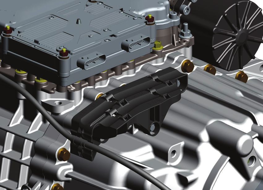
General Information

Important Information

                                                                                                                                    Information
                                                                                                                                      General
     This symbol is used throughout this                                   ! DANGER: Failure to follow indicated
     manual to call attention to critical                                    procedures will result in death or serious
     information where failure to adhere to                                  injury.
     safety specifications may result in personnel
     injury and/or component damage                                        ! WARNING: Failure to follow indicated
                                                                             procedures and/or safety requirements
     Departure from the instructions, choice                                 could result in death or serious injury.
     of tools, material or recommended parts
     mentioned in this publication may                                     ! CAUTION: Failure to follow indicated
     jeopardize safety.                                                      procedures could result in minor or
                                                                             moderate injury.

     Safety Requirements: Safety related                                      NOTICE: Failure to follow indicated
     requirements placed on the vehicle system by                             procedures could result in damage to the
     the transmission. Failure to comply may                                  transmission system.
     disable key and/or redundant safety features
     of the transmission system.
This publication has been assembled to assist the original equipment manufacturer (OEM) with proper design integration, han-
dling and assembly of the Endurant transmission. For additional information such as transmission operation, troubleshooting
and warranty information, please see the Other Useful Publications section in this manual.
The Endurant system is designed to operate correctly and safely when the requirements in this installation guide are met, in par-
ticular unintended or incorrect system operation could occur if requirements marked as a safety requirement are not complied
with.
Transmissions installed at OEM facilities shall meet all requirements as identified in the Application Guidelines TRAG2600 and be
approved by Eaton Application Engineering. Contact your OEM Application Engineering department or Eaton Application Engi-
neering for the proper Application Approval Form. All applications shall be submitted for approval.
Endurant transmissions are only compatible with engines as certified by Eaton Cummins Automated Transmission Technologies.
For specific engine information, please contact the engine manufacturer.
Failure to adhere to installation requirements or any handling and installation requirements may affect transmission performance
and/or warranty coverage.
Any reference to brand names in this publication is made as an example of the types of tools and materials recommended for use
and should not be considered an endorsement. Equivalents may be used.
Every effort has been made to ensure the accuracy of the information contained in this manual. However, Eaton and Eaton Cum-
mins Automated Transmission Technologies makes no warranty, either expressed or implied, based on the information provided
and reserves the right to discontinue or modify models and/or procedures and to change specifications at any time without
notice.
The vehicle OEM shall be responsible for producing parts that meet the requirements of this document.

                                                                                                                                1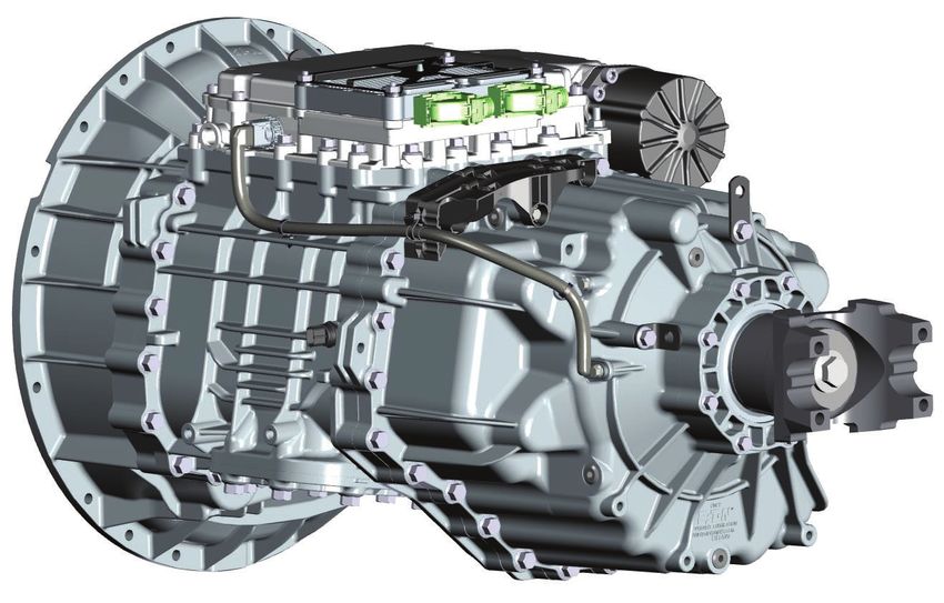
General Information

OEM Design Package
The OEM shall submit a design package to OEM customer support engineering for approval prior to any build. A design package
consists of the following information:
    •   Detailed drawing of battery power and ground scheme.
    •   Construction detail of individual wiring harnesses including harness routing location and clipping points.
    •   Specifications for air dryer, air compressor and filter filtration systems.
    •   A high-level schematic of the pneumatic system supplying the transmission.
    NOTICE: The Endurant system requires passive sealing on the clutch housing to ensure no foreign debris enters the clutch
    area. The OEM shall ensure that all openings in the engine flywheel housing are sealed.

Other Useful Publications
    •   Transmission Application Guidelines TRAG2600
    •   Automated Transmission Engine Configuration Settings Guide TRIG0910
    •   Lubrication Manual TCMT0021
    •   Approved Lubricant Supplier Manual TCMT0020
    •   Endurant Troubleshooting Guide TRTS0950
    •   Endurant Driver Instructions TRDR0950
    •   Endurant Service Manual TRSM0950
    •   Warranty Guide TCWY0900
    •   ISO Compressed Air Standard ISO 8573-1:2010(E)

Acronyms Associated with Endurant
    •   TCM: Transmission Control Module
    •   MTM: Mechatronic Transmission Module
    •   LCA: Linear Clutch Actuator

2
Section 1

                                                                                                                                   Introduction
Section 1: Introduction and General Information

System Features and Familiarization

Integration Features:
   •   12 volt vehicle electrical system capable.
   •   Compatible with ABS and ATC or ASR.
   •   Provides 8-bolt PTO opening.
   •   Product-specific J1939 messaging.
   •   18-tooth splined input shaft standard with all models.
   •   Includes 9 predetermined points for OEM harness routing and clipping.
   •   Clutch housing interface SAE No 1 diameter and bolt pattern.
   •   Pre-installed clutch release yoke and clutch release bearing.
   •   The master clutch is a single plate, self-adjusting, 430 mm diaphragm spring clutch with organic facings.
   •   No requirements for external lubrication or cooling systems.
   •   Provision for rear transmission support.

System Performance Features:
   •   Intelligent start gear selection automatically selects appropriate gear based on percent grade, vehicle weight and engine
       torque.
   •   Provides intelligent urge to move. This feature manages urge to move based on brake switch and grade inputs.
   •   Precision lube technology optimized to reduce churning losses and enhance fuel economy performance.
   •   Software-based accelerator pedal kick down feature.
   •   GearLogic™ neutral-coast and smart-coast technology.
   •   GearLogic™ acceleration management.

Mechanical Performance Features:
   •   Mechatronic transmission module (MTM) combines integration of actuation and sensors.
   •   Pneumatically operated gearbox and clutch actuators.
   •   Small lubricant sump volume for reduction in maintenance costs.

Diagnostic Features:
   •   Supported by ServiceRanger PC-based service tool.

                                                                                                                               3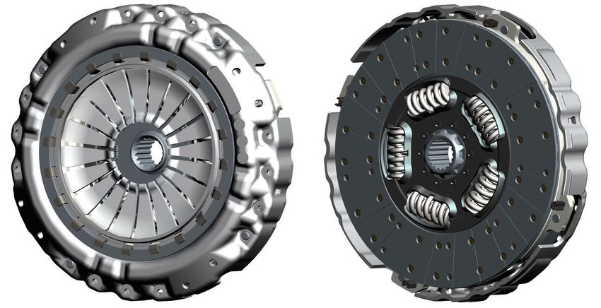
Section 1

Transmission Components Temperature Requirements
The temperature limit for all electrical and air system components is 221 °F (105 °C). If sufficient air gap between the heat source
and the following transmission components cannot be achieved, the OEM must provide proper methods of heat shielding to
ensure this limit is not exceeded. The components and systems to be protected include, but are not limited to, the mechatronic
transmission module, transmission control module, linear clutch actuator, lubrication sump, and output speed sensor harness.

Clutch and Transmission Identification

Clutch Assembly
The Endurant master clutch assembly is a single plate 430 mm diaphragm spring self-adjusting clutch with organic clutch disk
facings. This diaphragm spring is a push-to-release clutch which differs from legacy heavy duty Eaton clutches which are pull-to
release style clutch assemblies. Pre-adjustment of the clutch assembly is not necessary once installed to the engine flywheel.

4
Section 1

                                                                                                                                   Introduction
Transmission Assembly
The Endurant is an automated 12-speed twin countershaft transmission. Endurant is pneumatically shifted with high efficiency
gearing, precision lubrication, lightweight aluminum enclosures, and features GearLogic™ software.
Following is a nomenclature tree that describes the multiple configurations of the transmission model numbers:

                                   E E O       - 17    F 1 12 C

                           Eaton
                                                                                    Gear Ratio Set (A / B / C / D)
                       Endurant
                                                                                    Forward Speeds
                       Overdrive
                                                                                    Design Level
    Torque Capacity (1750 ft-lb)
                                                                                    Units for Torque (F = ft-lb; N = Nm)

All Endurant transmissions are supplied with component identification tags which define the transmission model number,
assembly number and serial number. Identification tags are located on the lower right side of the clutch housing.

                                                                                                                               5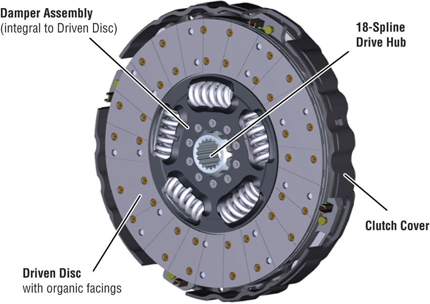
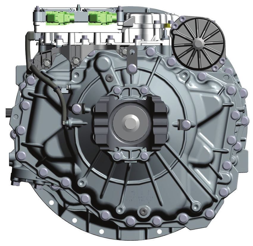
Section 1

Component and Touch-point Identification

Clutch Assembly Front (Driven Disk Installed)

Clutch Assembly Front (Driven Disk Removed)

6
Section 1

                                                    Introduction
Clutch Assembly Rear (Driven Disk Removed)

                                                7
Section 1 Transmission Assembly 8
Section 2

Section 2: Component Weight and Center of Gravity

                                                        Information
                                                        Component
Clutch Assembly: 118 lb. (53.5 kg)

Transmission Assembly: 512.2 lb (232.3 kg)

                                                    9
Section 3 Section 3: Vehicle Space Claim Cab Floor Access Plate A cab floor access plate is recommended for service access to the transmission top. A minimum access plate size of 15-inches x 12-inches is sufficient to allow service of the transmission control module, mechatronic transmission module, and linear clutch actuator. 10
Section 3

                                     Space Claim
Clutch Dimensions

                                11
Section 3 Transmission Dimensions 12
Section 3

                                                                                                                                        Space Claim
Driver Interface Device Space Claim
The Endurant driver interface device, or shift controller, does not have an established space claim for the vehicle. The OEM is
responsible for furnishing an appropriate driver interface device and corresponding space claim(s).
The driver interface device is not limited to a single device and may be multiple devices such as a stalk-type controller on the
steering column in combination with a dash mounted switch.

Shift Controller Label
There are no supplied shift labels available for the Endurant transmission. Furnishing of a shift label is the responsibility of the
vehicle OEM as it must reflect information specific to the OEM supplied driver interface device.
A shift label containing the following transmission specific information is recommended. This information is not required to be
identified as a Warning.
    •   Transmission make and model, number of forward and reverse speeds.
    •   That transmission air supply pressure of 90 psi (5.9bar) or greater is required for non-neutral engagement.
    •   Not to operate the vehicle if an alternator lamp or gage indicates low voltage.
    •   OEM specific instruction on how to start the vehicle and engage a forward or reverse gear.

                                                                                                                                   13
Section 4
Section 4: System and Feature Integration
Vehicle System Integration (VSI) Group
Integration requirements for the features identified in this section are maintained by the VSI group in what is known as a Truck
System Integration (TSI) documents. The TSI documents can vary by OEM, model year and transmission model. The TSI docu-
ments are also used to document interfaces with OEM proprietary. Integration of new features or integration of existing products
to new vehicle platforms should be discussed with the VSI group to identify the relevant requirements or to generate new
requirements.
The list below identifies the system features for which all integration requirements are maintained as TSI documents. A brief
description or high level requirement of each feature is provided and each feature is identified as “required” or “optional.”
Required: The OEM design shall meet all system integration requirements in order for the Endurant system to operate correctly
and safely and to avoid unintended or incorrect system operation.
Optional: The OEM has the option to integrate each feature as desired.
Required Feature Integration:
Engine
! WARNING: This is a safety requirement. To protect against malfunctioning ECUs, certified engines shall operate with set upper
limits on duration of TSC1 torque control requests. Additionally the engine shall receive and monitor a rolling counter (SPN4206)
and checksum (SPN4207) in issued TSC1 requests to evaluate the sending ECUs health. Failure to monitor sending ECU health
and limit TSC1 duration has potential to result in unintended vehicle acceleration, which may result in serious injury or death.
WARNING: This is a safety requirement. The engine Speed (J1939 EEC1 message) signal has the ability to inhibit or delay
! clutch disengagement and prevent speed rationality checks performed by the transmission. The vehicle system shall diagnose
the Engine Speed (J1939 EEC1 message) signal sent to the transmission TCM and ensure its integrity. Failure to diagnose in
range failures of the Engine Speed (J1939 EEC1 message) signal has the potential to increase vehicle stopping distance due to
delayed driveline disengagement or reduced ability to move the vehicle from adverse conditions, which may result in serious
injury or death.
WARNING: This is a safety requirement. The Engine Idle Speed (J1939 EC1 message) value has the ability to negatively influ-
! ence clutch disengagement if it is 10rpm or more below than the actual engine idle governor control point used by the engine
ECU. The vehicle system shall provide Engine Idle Speed (J1939 EC1 message) value that is identical to the control point of the
engine idle speed governor. Failure to broadcast a Engine Idle Speed (J1939 EC1 message) value that is identical to the true idle
control point has the potential to increase vehicle stopping distance due to delayed driveline disengagement, which may result in
serious injury or death.
Endurant transmissions are only compatible with engines as certified. The engine ECU shall contain the proper configuration set-
tings for Endurant transmission operation.
All required engine ECU settings can be found in the Automated Transmission Engine Configuration Settings Guide, publication
number TRIG0910. The publication can be found in the Literature Center at www.roadranger.com.
For specific engine information, please contact the engine manufacturer.
14Section 4
Calibration File
Integration
Feature
To achieve designed performance levels and activation of some features, the Endurant transmission requires a calibration file to
be installed onto the TCM in addition to the application software. For production vehicles the calibration file is installed at the
OEM Vehicle Equipment Programming Station (see VEPS section for more information), in-service vehicles can have the calibra-
tion files changed with the ServiceRanger service tool. Without a calibration file the transmission will have limited functionality
and will broadcast active fault SPN 629, FMI 13.
Calibration files contain parameters developed by calibration engineers that are vehicle configuration specific and are certified
under a part number. Calibration files may contain, but are not limited to, shift point maps, engine tuning parameters and OEM
specific tuning of features such as Urge to Move. See VEPS in Section 11 for more information.
Flywheel and Pilot Bearing
Flywheel
Dim Value (mm) Notes
A Ø258 +0.5 -0 Damper pocket
N 18 MIN Clearance to crank bolts
H Ø475 +0.1 -0 Flywheel pilot
M 8.0 to 9.0 With 0.8 x 45° chamfer
T M10 Fasteners x 12
F Ø450 Bolt circle
G 66.5 FW Hsg to friction surface
E 109.06 To rear of pilot brg
K 19 Pilot Brg width
L 72 Pilot Brg OD recommended
P 30 Pilot Brg ID required
15Section 4
Pilot Bearing
Eaton requires high quality pilot bearings in accordance with SAE J1731 Standard-Duty Pilot Bearings procured from Original
Equipment Manufacturers.
The maximum operating temperature of the pilot bearing in this system is 149°C. All components of the selected pilot bearing
should be capable of withstanding temperatures up to the maximum operating temperature of the pilot bearing. The table below
lists the requirements to follow when selecting a pilot bearing. Failure to comply with these requirements could result in early
failure of the pilot bearing. Pilot bearing failure usually results in a warranty claim with symptoms of clutch drag, clutch noise, or
input shaft pilot journal wear. In rare instances, pilot bearing failure may result in significant transmission damage.
Recommended Pilot Bearing requirements:
Pilot Bearing Specifications Recommendation
Bearing Standard SAE J1731: Pilot Bearings for Truck and
Bus Applications, Standard-Duty Pilot
Bearings
(NTN part number 2TS2-6306LLUAC3/
L781, 2TS2-6206LLUAC3/L781 or equiv-
alent)
Bearing Series 6306, 6206 or 5206
Bearing Internal Clearance C3*
Seal Material ACM / Polyacrylic
Grease Multemp ET-KH (Synthetic Ether and
Ester base oil with Aromatic Diurea thick-
ener)
Steel Elements TS2 Heat Stabilizatio
Note: *SAE J1731 Specifies C5 clearance. However, C3 or greater is acceptable.
NOTICE: Use of a bearing series not recommended does not provide adequate transmission input shaft interface.
Compatibility and Operation with J1939 Communication
Endurant transmissions utilize SAE J1939 communications protocols on multiple CAN networks as the primary means of com-
munication to other vehicle components. Endurant transmissions can support 250 Kbps or 500 Kbps networks and implement
automatic baud rate detection if necessary. Other vehicle network types and protocols (i.e. J1587, LIN or FlexRay) are not sup-
ported.
Engine Idle Fueling Inhibit
! WARNING: This is a safety requirement. To protect against the loss of the ability to open the clutch and disengage the driveline,
the vehicle system shall allow the transmission TCM to command the reduction or removal of engine idle torque in specific cir-
cumstances. Failure to allow the TCM to command the reduction or removal of engine idle torque in specific circumstances has
the potential to result in unintended acceleration, unintended direction, unintended motion and increasing stopping distance due
to the transmissions inability to disengage the driveline, which may result in serious injury or death.
WARNING: This is a safety requirement. For scenarios where the TCM is not capable of disengaging the clutch and no longer in
! communication with the vehicle, the vehicle system shall have the means to detect loss of communication to an in gear transmis-
sion and to independently reduce or remove idle torque in appropriate circumstances. Failure to detect an unresponsive trans-
mission that is in gear and reduce idle torque when appropriate has the potential to cause unintended vehicle acceleration and
unintended vehicle motion or to increase vehicle stopping distance due to inability to disengage the driveline, which may result in
serious injury or death.
16Section 4
Endurant transmissions are designed to utilize the Transmission Idle Governor Fueling Inhibit signals that are part of the J1939
Integration
Feature
ESR and EC2 message structure in the rare event the transmission is unable to disengage the driveline. Endurant-compatible
engines are required to support these messages. Implementation is guided by the February 2016, SAE J1939 Digital Annex Fig-
ure SPN2432_A.
Driver Interface Device
!
WARNING: This is a safety requirement. The state of the driver interface device shall be communicated by dual outputs to
improve robustness to single point errors in communication to the transmission. Failure to mitigate the single point failure of the
driver interface device has the potential to result in unintended vehicle direction, unintended motion or reduced ability to move
the vehicle from adverse conditions, which may result in serious injury or death.
The Endurant TCM can communicate with a driver interface device over one of two architectures, a dual CAN bus interface or a
single CAN bus network with a PWM signal.
Protected Power from TCM
J1939 Network
OEM Driver
TC1 (mode request) ETC7 (actual) Endurant
Interface Device
Transmission
(DID)
CI (response to RQST) RQST (requests CI)
PWM Link (mirrors TC1)
WARNING: This is a safety requirement. In order to not confuse a vehicle driver or conflict with the gear display during a mode
! transition, for driver interface devices equipped with illuminated mode indicators, the interface shall flash the requested mode
indicator (and hold previous mode solid) if the mode feedback from the J1939 ETC7 message does not match the requested
mode. Failure to communicate a mode change and agree with a vehicle driver display on driver interface devices equipped with
illuminated mode indicators has the potential to cause unintended vehicle direction and unintended vehicle motion, which may
result in serious injury or death.
WARNING: This is a safety requirement. To prevent miss-informing the vehicle driver, for driver interface devices equipped with
! illuminated mode indicators, the driver interface device shall show an error state or warning light within 500ms if the vehicle
stops receiving valid J1939 ETC7 messages from the TCM. Failure to notify the driver of lost communication with the transmis-
sion has the potential to cause unintended vehicle direction and unintended vehicle motion, which may result in serious injury or
death.
A typical driver interface device (DID) allows driver selection of “RNDML” (reverse, neutral, drive, manual, and low modes). All
driver inputs are treated as requests and honored as dictated by vehicle operating conditions to ensure safe operation. Confirma-
tion of the Transmission Requested Gear Feedback signal is found in the J1939 ETC7 message.
Please see “Section 7: Electrical System Requirements” on page 26 for details on DID electrical and communications interfaces
to the transmission system.
17Section 4
• Driver Interface Device Modes:
- Reverse Mode: Will initiate a sequence that puts the transmission in gearbox Reverse. The TCM will automatically
select, engage, and shift to the appropriate Reverse gear to the engine/road speed conditions and vehicle configu-
ration.
- Neutral Mode: Initiates a sequence that puts the transmission in gearbox Neutral where no torque is transferred
through the transmission.
- Drive (Forward) Mode: Will initiate a sequence of events that places the transmission in gearbox into Drive, the
standard mode of transmission operation. The TCM will automatically select, engage, and shift to the forward gear
appropriate to the engine/road speed conditions and vehicle configuration.
- Manual (Forward) Mode: Initiates a sequence that puts the transmission in gearbox Manual. The transmission
engages a forward gear, but inhibits the automatic shifting. Shifts in Manual mode are accomplished by sending
the appropriate UP or DOWN shift request. Shifts are allowed if the conditions satisfy vehicle limit criteria. Both sin-
gle gear step and skip shifts are allowed.
- Low (Forward) Mode: Initiates a sequence that puts the transmission in gearbox Low. The transmission engages a
forward gear then executes a downshifting sequence with higher downshift points.
Note: Manual gear shift requests are allowed when the transmission is in Manual, Drive, or Reverse mode. The driver initi-
ates a gear shift by requesting a gear Upshift or Downshift. The manually requested shift is allowed if vehicle conditions sat-
isfy the shift criteria for the current gearbox mode.
Gear Display
! WARNING: This is a safety requirement. To inform the vehicle driver of the transmission state, the vehicle driver display system
shall provide a minimum of 2 digits to show transmission mode and status information conveyed via the Transmission Current
Range (J1939 ETC2 message) signal. Failure to notify the driver and provide feedback information on the state of the transmis-
sion has the potential to cause unintended vehicle direction, unintended vehicle motion or other hazards associated with an unin-
formed driver, which may result in serious injury or death.
! WARNING: This is a safety requirement. To prevent miss-informing the vehicle driver, the vehicle driver display system shall
show an error state or warning light within 500ms if the vehicle stops receiving valid ETC2 messages from the TCM. Failure to
notify the driver of lost communication with the transmission has the potential to cause unintended vehicle direction, unintended
vehicle motion or other hazards associated with a misled driver, which may result in serious injury or death.
A gear display is required for proper transmission operation. The OEM is responsible for supplying the gear display and wiring
per governmental safety standards, such as the Federal Motor Vehicle Safety Standard (FMVSS)
The gear display offers real-time information pertaining to current engaged gear, engagement status during gear shifting, trans-
mission synchronization during shifting and transmission fault status. The gear display interfaces with the transmission with the
J1939 ETC2 message. Two characters messages can also be displayed through the gear display as a means to communicate
transmission information to the driver (i.e. “CA” for Clutch Abuse). Messaging content can vary by OEM, please contact VSI for
specific details.
Alert Tone
! WARNING: This is a safety requirement. This is a safety requirement. To complement the visible warnings of the driver display
system the vehicle system shall have an Audio Warning capability to communicate warning status to the driver including those
communicated from the TCM. Failure to additionally notify the driver by audible means increases the likelihood a hazardous con-
dition, if encountered, could go unnoticed by the driver, which may result in serious injury or death.
18Section 4
Required tone information shall be conveyed from the Endurant transmissions via the control character of the Transmission Cur-
Integration
Feature
rent Range signal in the SAE J1939 ETC2 message. It is the OEM’s responsibility to choose tone attributes (i.e. type, duration,
frequency) for a given set of conditions. OEM’s also have the ability to add audible notifications in addition to those explicitly sent
from the transmission by triggering off other sources such as the Message Display, Gear Display and Driver Interface Device.
Service Lamps
Red and Amber transmission indicator lamps are required on the dash. The lamps shall respond to transmission broadcast
J1939 DM1 messages. An Amber Lamp signal from the transmission would indicate the need for service while a Red Lamp sig-
nal would indicate the immediate need to cease driving and/or that vehicle motion is prohibited.
Accelerator Pedal
! WARNING: This is a safety requirement. The accelerator pedal system is the primary driver input for vehicle acceleration, the
accelerator pedal shall confirm pedal movement by a minimum of two independent methods before the vehicle system transmits
non-zero Accelerator Pedal Position (SPN91) or Driver's Demand Engine-Percent Torque (SPN512) values to the transmission.
Failure to provide an input that does not accurately represent the vehicle drivers intent has the potential to cause the transmission
to engage the driveline resulting in unintended vehicle motion, which may result in serious injury or death.
Hill Start Aid (HSA) and Anti-lock Braking System (ABS)
WARNING: This is a safety requirement. The vehicle system shall provide accurate entry and exit information of ABS (skid)
! events to the transmission via a J1939 EBC1 Message signal. Failure to notify the transmission of skid events creates potential
for reduction in lateral control of the vehicle due to loss of power steering (engine stalling) or abrupt driveline retardation, which
may result in serious injury or death.
The OEM is required to install a hill start aid system in the vehicle. This often includes the addition of brake system valves and
unique ABS controllers required by the brake manufacturer. The hill start aid system prevents unwanted vehicle movement on
steep grades when transitioning from the brake pedal to the accelerator pedal. When hill start aid is activated, the system applies
the foundation brakes for up to 3 seconds during operator brake-to-throttle transitions while the vehicle is operating forward or
reverse, in either a 1% or greater grade (either incline or decline).
The hill start aid requires an operator accessible on/off override momentary control switch. The OEM is responsible for supplying
the on/off control switch. The override switch is part of the brake system. Contact the brake controller manufacturer for hill start
aid system and switch requirements.
The OEM is also responsible for providing a lamp to communicate system status messages of the “hill hold” switch. It is recom-
mended that the light be amber in color and illuminate when the system is disabled or faulted.
Auto Neutral
An auto neutral feature is provided with this transmission which forces the transmission into neutral in all instances when the
parking brake is applied. The Endurant system requires the use of the Park Brake Switch signal in the J1939 CCVS1 message to
enable function of the Auto Neutral feature.
Front Axle Speed
! WARNING: This is a safety requirement. To diagnose in-range transmission speed sensor failures and detect abnormal driveline
accelerations (i.e. skid, slip) the vehicle system shall provide the transmission the Front Axle Speed (J1939 EBC2 Message) sig-
nal from an unpowered front axle. Failure to provide the transmission an accurate Front Axle Speed (J1939 EBC2 Message) sig-
nal has the potential to cause reduction in lateral control of the vehicle due to loss of power steering (engine stalling) or abrupt
driveline retardation, which may result in serious injury or death.
19Section 4
The Endurant transmission also requires relative front wheel speed signals from the J1939 EBC2 Message for turning detection.
NOTICE: The current implementation of front axle speeds assumes an unpowered front axle. At this time Endurant is not
approved for use with all-wheel drive powertrain configurations and/or powered front axles.
Parking Brake
WARNING: This is a safety requirement. The Park Brake Switch (J1939 CCVS1 message) signal will allow the Urge-to-Move
! feature when received as “off” by the TCM (and service breaks have already been released) to launch the vehicle. As such the
vehicle system shall diagnose the Park Brake Switch (J1939 CCVS1 message) signal to protect against in range failures. The
vehicle system shall also update the state of the Park Break Switch (J1939 CCVS1 message) signal within 1 second of the driver
pressing or releasing the park break. Failure to provide an accurate Park Brake Switch (J1939 CCVS1 message) signal in a timely
manner has the potential to cause the transmission to engage the driveline resulting in unintended vehicle motion, which may
result in serious injury or death.
Optional Feature Integration:
Using Rear Supports
The OEM is responsible for determining if rear supports are needed. If rear supports are desired, the OEM is responsible for rear
mount design. Refer to OEM for rear mount fastener torque specifications.
When a transmission rear support is utilized, the maximum spring support reaction force shall not exceed 2,670 Newton.
Configuration Parameters
In addition to the required calibration file previously described, the Endurant transmission also has optional configuration param-
eters which can be controlled independent of the calibration file, although the calibration file has the ability to change the default
configuration parameters. Configuration parameters are features, functions, and options that can be selected, enabled, disabled,
or modified with discrete values by authorized internal or external parties. For production vehicles the default configuration
parameters can be changed by the OEM Vehicle Equipment Programming Station (see VEPS section), in-service vehicles can
have the configuration parameters changed with the ServiceRanger service tool provided the user has the correct permission
level for a particular parameter.
Message Display
Endurant transmissions are capable of enhanced communication beyond the gear display through a variety of J1939 communi-
cation signals. Specific combinations of J1939 communications from the transmission can be used as triggers to display read-
able text by an appropriate dash display as desired by the vehicle OEM. For suggested text, available triggers and new triggers
please contact VSI.
Cruise Control and Advanced Cruise Control Systems
The Endurant system uses J1939 information provided by the cruise control and advanced cruise control systems (Adaptive
Cruise Control and Predictive Cruise Control), if present and configured properly, for certain features and functions. For further
information on this feature please contact VSI.
20Section 4
Stability and Traction Control Systems
Integration
Feature
WARNING: This is a safety requirement. For vehicles equipped with optional stability (ASR) and traction control (ATC) systems,
! the vehicle system shall provide accurate entry and exit information of wheel slip events and system activation to the transmis-
sion via a J1939 EBC1 Message signal. Failure to notify the transmission of such events creates potential for reduction in lateral
control of the vehicle due to loss of power steering (engine stalling) or abrupt driveline retardation, which may result in serious
injury or death.
The Endurant system is capable of inhibiting shifts during many vehicle dynamic situations from information provided by vehicle
systems over the J1939 network. Anti-slip and stability control events will all inhibit shifting in the transmission when the corre-
sponding J1939 EBC1 Messages are received. The transmission system also has secondary independent detection capability for
skid and slip events in the driveline.
Neutral Coast
The Endurant system has the ability to disengage the driveline to reduce parasitic losses of the powertrain and use the momen-
tum of the vehicle to maintain speed for improved fuel economy under certain drive cycles. This feature can be set up to either
use the transmissions internal coast decision logic or to accept a J1939 disengagement request from other vehicle systems (i.e.
the engine). For further information on this feature please contact VSI.
Urge-to-Move and Service Brakes
The transmission system can provide an optional Urge-to-Move feature that will automatically provide a low level of torque trans-
fer through the clutch once the brake pedal has been released. Torque transfer will continue to increase fully locking the clutch
and then enter Creep Mode at engine idle speed.
! WARNING: This is a safety requirement. For use of optional advanced transmission functions such as Urge-to-Move and Creep
Mode, additional brake system information and sensing is required beyond the basic Brake Switch (J1939 CCVS1 message) sig-
nal. Brake Application Pressure (J1939 B message) or Brake Pedal Position (J1939 EBC1 message) are often one of the addi-
tional signals required and are sourced from independent sensors other than that used by the Brake Switch (J1939 CCVS1
message) signal. Specific requirements are dependent on the brake system architecture, availability of other signals and signal
transmission rates. Failure to properly mitigate a single point failure of the service brake sensor and Brake Switch (J1939 CCVS1
message) signal has the potential to result in unintended motion, unintended acceleration and increased stopping distance of the
vehicle due to the transmissions engagement/disengagement the driveline, which may result in serious injury or death.
Redundant J1939 Communication (CAN B)
The Endurant transmission system will experience several debilitating symptoms with the loss of primary J1939 communication.
The OEM has the option to design redundant J1939 communication to the transmission to reduce these affects if so desired. The
level of remaining functionality of the automated transmission system, depending on the level of integration of secondary J1939
communication, is as follows:
• No secondary Network: Fail in place with no functionality.
• Secondary Network, “Listen Only”: Launch permitted but limited to start gear, no shifting.
• Second Network, fully redundant: Driving and shifting permitted, loss of some functions.
The Endurant TCM continually broadcasts the Transmission Communications Failure Idle Torque Limit signal in the J1939 TCFG2
message as last instructions should the engine-to-transmission communication be lost.
Specific functionality will be dependent on the J1939 messages supported by the secondary network.
Power Take-Off (PTO) over J1939
In addition to the PTO hardwire options outlined in “Section 9: PTO Inputs and Configurations” on page 37, the Endurant trans-
mission is capable of interfacing with transmission mounted PTO devices though other vehicle ECUs such as a cab or body con-
troller. 8-bolt countershaft (PTO 1) and rear-mount through shaft (PTO 2) hand shaking is communicated through the J1939
PTODE message. Implementation is guided by the SAE J1939 Digital Annex Figure PGN64932_B.
21Section 5
Section 5: Lubrication Requirements
NOTICE: The transmission lubricant shall be approved per Eaton PS-386 requirements as documented in the Lubrication Manual
TCMT0021.
A list of approved lubricants and suppliers can be found in the Approved Lubricant Supplier Manual, TCMT0020. Not using the
required lubricant will result in degraded performance and shortened life of the product.
• Lubrication capacity: 7.5 liters
• Additives and / or friction modifiers are not approved. Additives of any kind will result in unpredictable consequences. No
liability of any kind will be accepted for any damage resulting from the use of such additives.
• Failure to use the required lubricant will affect the transmission performance and the warranty coverage.
• All approved lubricants are required to display the PS-386 approved logo.
22Section 6
Pneumatic System
Requirements
Section 6: Pneumatic System Requirements
Supply Pressure
WARNING: This is a safety requirement. To maintain transmission functionality, the vehicle system shall have the air compres-
! sor OFF set no higher than 130psig (9.0bar). Failure to limit transmission air supply pressure below 130psig (9.0bar) has the
potential to increase vehicle stopping distance due to the transmissions inability to disengage the driveline, which may result in
serious injury or death.
WARNING: This is a safety requirement. To prevent transmission damage the vehicle system shall have a pressure relief valve
! in the supply system set no higher than 150psig (10.3bar). Failure to limit transmission air supply pressure below 150psig
(10.3bar) has the potential to increase vehicle stopping distance due to the transmissions inability to disengage the driveline,
which may result in serious injury or death.
For optimal performance, the Endurant transmission requires a nominal air supply operating range between 99 psi (6.8 bar) and
130 psi (9.0 bar). Air supply outside this range can result in degraded or complete loss of transmission shift capabilities. The fol-
lowing figure summaries the significant thresholds for various air supply pressures.
NOTICE: Actions taken by the Endurant transmission in response to air supply pressures are not symmetrical and vary depend-
ing on if air supply pressure is increasing or decreasing such as transmission functionality allowed above 90 psi (5.9 bar) but not
degraded until below 80 psi (5.5 bar).
Pressure Range Description Bar Ref. PSI Response
Transmission Function Permitted 5.9 90 System Low Air Warning turns off. Gear engagement
permitted.
Lower Operating Range 6.8 99
Upper Operating Range 9.0 130
Transmission Low Air Notification 5.5 80 (SPN-37 FMI-18): Transmission low pressure warning
turns ON. Transmission remains functional at
degraded performance (e.g. Non-N modes prohibited
and upshifts not allowed; downshifts will continue)
Transmission Low Air Warning 5.2 75 (SPN-37 FMI-1): Transmission low pressure warning
continues, system will then attempt to disengage
driveline when or if it becomes appropriate.
Air Consumption
The table below shows the worst-case air consumption. Actual air consumption is a function of the transmission control algo-
rithms and will be less in normal operation. These totals assume open clutch shifting for each shift.
Shift Air Consumption in L at 120 PSI (8.27 bar)
N-1 0.50
1-2 0.38
2-3 0.49
3-4 0.38
23Section 6
4-5 0.43
5-6 0.38
6-7 0.76
7-8 0.38
8-9 0.49
9-10 0.38
10-11 0.43
11-12 0.38
TOTAL 5.39
Air Quality
The Endurant transmission air supply is required to meet or exceeded ISO 8573-1:2010 7.3.4. The vehicle air system supplying
the transmission shall use a high quality commercially available oil coalescing air dryer. Air quality for solid contamination shall
meet a minimum of ISO 8573 Class 7. Air quality for water contamination shall meet a minimum of ISO8573-1 Class 3. Air qual-
ity for oil contamination shall meet a minimum of ISO 8573-1 Class 4.
Limits of relative humidity of the supplied air must be below the values listed below. The dew point reduction of the air supply
system shall meet a minimum of ISO 8573 Class3.
Ambient Temperature -40 (-40) -20 (-4) 0 (32) 20 (68) 40 (104) 60 (140) 80 (176)
˚C (˚F)
Relative Humidity % 8.5 12.5 17.0 25.0 32.0 37.0 42.0
NOTICE: Air additives such as alcohol devices should not be permitted to enter the transmission air supply. Additives could cause
damage to air system components, which could lead to degraded transmission performance.
Air Supply Requirements
WARNING: Loss of pneumatic integrity of the transmission air supply line (blow off) may result in rapid loss of transmission air
! supply pressure without warning. Vehicle OEMs shall select appropriate hose, fittings and routing for the vehicle application and
ensure proper assembly in vehicle. Failure to design and properly install an adequate transmission air supply system may
increase the chance of rapid loss of air supply pressure without warning having potential to cause unintended motion, increased
vehicle stopping distance or reduced ability to move the vehicle from adverse conditions, which may result in serious injury or
death.
Air Supply
WARNING: This is a safety requirement. To ensure that the air pressure sensed by the transmission represents a usable volume
! of air and to isolate the transmission air supply from other vehicle air systems, the transmission air supply shall have unre-
stricted access to a dedicated air volume of at least 10-liters and be isolated from upstream air supply by a check valve. Failure to
provide the transmission with unrestricted access to a usable volume of air and isolate it from other vehicle air systems has the
potential to increase vehicle stopping distance or reduced ability to move the vehicle from adverse conditions, which may result
in serious injury or death.
• Clean, dry air is required for the transmission system to shift properly.
• If desired, OEMs may choose to install a Pressure Protection Valve (PPV) in-line with the required check valve.
24Section 6
Pneumatic System
Requirements
Port
• The mechatronic transmission module (MTM) has an ISO 6149-1 metric straight thread o-ring port for the air line con-
nection. The port size is an M18x1.5, with metric ISO 261 metric thread.
Fitting
• It is recommended that an O-ring fitting that mates to the ISO 6149-1 M18x1.5 port be used. O-ring material should be
selected based on OEM experience with air systems. The operating temperature limit for all electrical and air system
components is 221 °F (105 °C)
Hose
• The OEM shall select the air hose based upon government regulations and experience with vehicle air systems.
• The inside diameter of the air hose shall not be less than 12 mm.
Hose Routing
• Air lines should not be routed or attached at the bottom air tank fittings to avoid any chance of introducing moisture into
the airline.
• Proper air hose routing techniques shall be followed with appropriate clipping points to eliminate any chaffing that may
occur on the hose.
• OEM air supply hose shall not be routed and clipped to the pre-installed output shaft speed sensor harness.
25Section 7
Section 7: Electrical System Requirements
NOTICE: “Power” refers to both power positive and power negative supply. This is typically battery plus and battery negative.
“Switched ignition” refers to power that is enabled with ignition key operation.
Power Requirements
• The vehicle primary power system shall be a 12-volt system.
• The OEM shall provide power to the TCM that does not exceed a steady state voltage of 16 volts DC.
• The vehicle shall have a negative ground power system.
! WARNING: This is a safety requirement. To eliminate any single point failures that could incapacitate the TCM, particularly while
the driveline is engaged, the vehicle system shall provide two independently fused power positive supply lines, each capable of
sustaining the power requirements of the TCM. These lines shall be continuous between the TCM vehicle connector and a power
source such that a single point failure does not disrupt power to the TCM. Failure to protect the TCM power supply lines from sin-
gle point failure has the potential to cause:
- Unintended vehicle acceleration
- Unintended vehicle motion
- Increased stopping distance
- Physical harm related to service
- Serious injury or death
• The OEM shall provide two independent power negative supply lines, each capable of sustaining the power require-
ments. These lines shall be continuous between the TCM vehicle connector and a power source such that a single point
failure does not disrupt power to the TCM.
• The OEM shall provide power wiring to the TCM such that the differential voltage (TCM negative subtracted from TCM
positive, for each individual power line) shall exceed 9 VDC at a steady state load of 15 amps as configured for a 12-volt.
• The OEM shall provide switched ignition wiring to the TCM such that the differential voltage (TCM negative subtracted
from TCM Switched Ignition input) shall exceed 9 VDC at a steady state load of 1 amp as configured for a 12-volt sys-
tem.
• Power and switched ignition to the TCM shall not drop below 9 volts DC during the engine start process.
• Engine start interlock shall meet FMVSS 102 Section 3.1.3 standards: “The engine starter shall be inoperative when the
transmission shift lever is in a non-neutral position”. See “typical start enable relay circuit” in this section.
- Hardwired start enable relay circuits are not required if J1939 equivalent is available.
• If a disconnect switch is used for the engine control module (ECM), it shall be configured such that it also removes
power to the transmission control module (TCM).
NOTICE: Removal of ignition power (pin V-10) quickly followed the removal of constant power (pins V-6 and V16) may not
provided the TCM adequate time to power down and could result in loss of information.
26Section 7
Electrical System
Requirements
Mating Connector and Terminal Requirements
• Connectors shall be designed for use in the heavy-duty industry, conforming to SAE-J2030 and SAE-J1455.
• Terminal position assurance (TPA) and connector position assurance (CPA) devices shall be used on connector systems
that support those devices.
• When interfacing to Endurant components, use connector systems specified within Endurant documentation or an
approved equivalent.
• Mating halves of terminal systems shall use plating materials that are compatible with each other.
• Terminal plating shall be gold for all TCM interfaces.
- Recommended minimum plating thickness of 0.75 microns of gold over 1.2 micron of nickel.
• Required wire size:
- The cable for the Delphi 20-way connector B (13976573) shall be 18 TXL for all wires.
- The cable for the Delphi 20-way connector V (13885474) for Pins 5, 6, 15 and 16 shall be 16 TXL.
- The cable for the Delphi 20-way connector V (13885474) for all Pins EXCEPT 5, 6, 15 and 16 shall be 18 TXL.
NOTICE: Specified cable sizes ensure proper connector sealing and current carrying capacity.
NOTICE: Cable cross-sectional area and insulation are specified to ensure proper connector cable sealing and current carrying
capacity.
Electrical Sealing Requirements
• Separable connectors outside of the cab shall be sealed per SAE-J2030 standards.
• Unused connectors shall have sealed mating connectors or plugs.
• Unused terminal cavities shall have sealed mating connectors or plugs.
• Seals shall be selected based upon cable outer diameter and connector cavity specifications.
Network Communication Requirements
The use of either shielded or unshielded twisted pair shall be an OEM decision based upon EMC validation testing.
• Required controller area network (CAN) communication with the vehicle engine.
• The OEM is provided the option of supporting CAN communications utilizing the SAE J1939 CAN physical layer with
shielded twisted pair data cable (SAE J1939/11) or unshielded twisted pair data cable (SAE J1939/15).
- For shielded, twisted-pair installations (STP), the data link cable, connectors, and termination shall meet the perfor-
mance and assembly requirements of SAE J1939/11.
- For unshielded, twisted-pair installations (UTP), the data link cable, connectors, and termination shall meet the per-
formance and assembly requirements of SAE J1939/15.
• Twisted pair requirements:
- 2 Cables = 10 Twists / 25.4 cm
- 3 Cables = 8 Twists / 25.4 cm
- (16 and 18 Gauge Cable Only)
27Section 7
Vehicle Service Requirements for Electronics
• Battery positive and negative circuits to the Endurant TCM must be disconnected prior to any type of welding on the
vehicle.
• Battery negative must be disconnected prior to removal or installation of TCM harness connectors.
• Removal and/or replacement of a battery shall not disturb the terminating connectors of the TCM.
OEM Interface Connections
• There will be two Delphi 20-way connectors that mate with the transmission control module.
• The Delphi 20-way vehicle connector (Delphi P/N 13885474 – index key V) is configured to receive 16 circuits utilizing
0.8 mm2 (18 AWG) TXL wire and 4 circuits utilizing 1.0 mm2 (16 AWG) TXL wire. The four 1.0 mm 2 (16 AWG) circuits
are for the TCM power and ground circuits. These circuits are located in cavities 5, 6, 15 and 16 of the vehicle connector.
The vehicle connector is dark gray in color. See the respective charts below for more detail.
• The Delphi 20-way body connector (Delphi P/N 13976573 – index key B) is configured to receive 20 circuits that utilize
0.8 mm2 (18 AWG) TXL wire. The body connector is light gray in color. See the respective charts below for more detail.
• The transmission will be delivered with two green environmental shipping caps (Delphi P/N 13885475) installed.
• A Connector Position Assurance (CPA) (Delphi P/N 15357145) shall be used to secure the fully engaged connector lever
lock in the latched position.
NOTICE: All unused connector cavities shall be plugged to prevent water intrusion. Both connectors use the Delphi plug (Delphi
P/N 15305171). Use as required.
28Section 7
Electrical System
Requirements
20-Way Vehicle Connector
Vehicle Connector Pin No. Wire AWG Circuit Description
V-1 18 Plugged (not used)
V-2 18 Plugged (not used)
V-3 18 Plugged (not used)
V-4 18 Start Enable – Negative
V-5 16 Battery Negative 1*
V-6 16 Battery Positive 1*
V-7 18 Fluid Pressure Sensor – Signal
V-8 18 Protected Power Return
V-9 18 Driver Interface Device (Mode request from DID)
V-10 18 Ignition Wakeup (Input)
V-11 18 CAN A – High (Primary J1939)
V-12 18 CAN A – Low (Primary J1939)
V-13 18 CAN A – Shield (Primary J1939)
V-14 18 Start Enable – Positive
V-15 16 Battery Negative 2*
V-16 16 Battery Positive 2*
V-17 18 Protected Power (Output)
V-18 18 Fluid Pressure Sensor - Ground
V-19 18 Fluid Pressure Sensor - Power
V-20 18 Plugged (not used)
* Refers to “power requirements” identified at the beginning of Section 7
29Section 7
Suggested parts for TCM vehicle connector
Component Delphi Part # Quantity
Connector Body 13885474 1
Terminal 15471370 20
Secondary Look 13885454 1
Connector Position Assurance (CPA) 15357145 1
Cab Seal 15305351 20
Back shell Cover 15476351 1
20-Way Body Connector
Vehicle Connector Pin No. Wire AWG Circuit Description
B-1 18 Reverse (Output)
B-2 18 PTO Engage (Output)
B-3 18 Range Output
B-4 18 Plugged (not used)
B-5 18 Body I/O Return
B-6 18 Plugged (not used)
B-7 18 CAN B – High (Redundant J1939)
B-8 18 CAN B – Low (Redundant J1939)
B-9 18 Plugged (not used)
B-10 18 Plugged (not used)
B-11 18 Test Point – Vbatt (Do Not Use)
B-12 18 Test Point – Ignition (Do Not Use)
B-13 18 Test Point – Ground (Do Not Use)
B-14 18 Body I/O Return
30Section 7
Electrical System
Requirements
B-15 18 PTO Request (Input)
B-16 18 PTO Confirm
B-17 18 Plugged (not used)
B-18 18 Plugged (not used)
B-19 18 CAN A – Low (Primary J1939)
B-20 18 CAN A – High (Primary J1939)
Suggested parts for TCM body connector
Component Delphi Part # Quantity
Connector Body 13976573 1
Terminal 15471370 20
Secondary Look 15366676 1
Connector Position Assurance (CPA) 15357145 1
Cable Seal 15305351 20
Back shell Cover 15476351 1
Fluid Pressure Sensor
1 2 3
For transmissions equipped with the fluid pressure sensor, the OEM vehicle wiring harness is required to make the connection
between the fluid pressure sensor and the TCM vehicle connector.
Vehicle Connector Pin No. Wire AWG Fluid Pressure Sensor Connector Pin No. Circuit Description
V-7 18 3 Fluid Pressure – Signal
V-18 18 2 Fluid Pressure – Ground
V-19 18 1 Fluid Pressure – Power
Suggested parts for fluid pressure sensor harness
Component TE AMP Part # Quantity
MCON LL Housing 1-1718644-1 (125C) or 1
1-1718644-5 (150C)
Terminals 7-1452671-2 3
Cable Seal 967067-1 3
31You can also read