Experimental and modeling investigations of the behaviors of syntactic foam sandwich panels with lattice webs under crushing loads
←
→
Page content transcription
If your browser does not render page correctly, please read the page content below
Reviews on Advanced Materials Science 2021; 60: 450–465
Research Article
Zhilin Chen, Yu Zhang, Jun Wang*, Hota GangaRao, Ruifeng Liang, Yuanhui Zhang, and
David Hui
Experimental and modeling investigations of the
behaviors of syntactic foam sandwich panels
with lattice webs under crushing loads
https://doi.org/10.1515/rams-2021-0040 applications in bridge decks, ship decks, carriages, airframes,
received March 17, 2021; accepted May 13, 2021 wall panels, anticollision guard rails and bumpers, and
Abstract: The composite sandwich structures with foam railway sleepers.
core and fiber-reinforced polymer skin are prone to damage Keywords: sandwich panel, syntactic foam, glass fiber-
under local impact. The mechanical behavior of sandwich reinforced polymer skin, mechanical properties, finite-
panels (glass fiber-reinforced polymer [GFRP] skin rein- element model
forced with lattice webs and syntactic foams core) is studied
under crushing load. The crushing behavior, failure modes,
and energy absorption are correlated with the number of
GFRP layers in facesheets and webs, fiber volume fractions 1 Introduction
of facesheets in both longitudinal and transverse directions,
and density and thickness of syntactic foam. The test results The composite sandwich structures, which are three-layered
revealed that increasing the number of FRP layers of lattice configurations composed of foam core and fiber-reinforced
webs was an effective way to enhance the energy absorp- polymer skin, are prone to damage under local impact owing
tion of sandwich panels without remarkable increase in the to their limited skin thicknesses and low core strengths
peak load. Moreover, a three-dimensional finite-element [1–3]. Core materials with high strengths and stiffnesses
(FE) model was developed to simulate the mechanical beha- are preferred in high-energy demand applications.
vior of the syntactic foam sandwich panels, and the numer- Researchers have paid much attention on the mechanical
ical results were compared with the experimental results. performances of composite materials [4–6]. Syntactic foams
Then, the verified FE model was applied to conduct exten- consist of hollow spheres, which have low specific density
sive parametric studies. Finally, based on experimental and and high hardness, embedded in a polymer matrix [7]. The
numerical results, the optimal design of syntactic foam hollow spheres may be composed of glass, carbon, ceramic,
sandwich structures as energy absorption members was metal, and polymer-based materials, while polymer resins
obtained. This study provides theoretical basis and design are used as binders [8,9]. The syntactic foams provide high
reference of a novel syntactic foam sandwich structure for compressive strengths, excellent damage tolerances, and
energy absorption, which make them ideal core materials
for composite sandwich structures [10]. However, the skin–
core delamination is a major technical barrier to achieve full
strength and energy absorption of sandwich composites
* Corresponding author: Jun Wang, Bridge Engineering Department, [11]. Moreover, unresolved issues associated with the failure
College of Civil Engineering, Nanjing Tech University, Nanjing
mechanism and crashworthiness of syntactic foam sand-
211816, China, e-mail: wangjun3312@njtech.edu.cn
Zhilin Chen, Yu Zhang: Bridge Engineering Department, College of wich composites under crushing loads still exist. In this
Civil Engineering, Nanjing Tech University, Nanjing 211816, China study, a novel syntactic foam sandwich structure with lat-
Hota GangaRao, Ruifeng Liang: Department of Civil and tice webs is developed, which has the potential to enhance
Environmental Engineering, West Virginia University, Morgantown, structural performance and energy absorption ability,
WV 26506, United States of America
hence the skin–core delamination can be improved. The
Yuanhui Zhang: China Construction Eighth Engineering Division
Corp., Ltd., Shanghai 200112, China
crushing behavior of the syntactic foam sandwich panels
David Hui: Department of Mechanical Engineering, University of New is investigated to understand the mechanical properties and
Orleans, New Orleans, LA 70148, United States of America associated failure mechanisms. The resulting novel
Open Access. © 2021 Zhilin Chen et al., published by De Gruyter. This work is licensed under the Creative Commons Attribution 4.0
International License.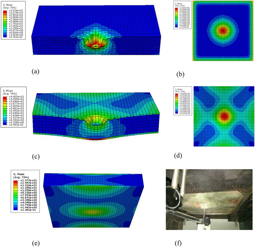
Crushing behaviors of syntactic foam sandwich panels with lattice web 451
syntactic foam sandwich structures are expected to be light- impregnated paper honeycomb (RIPH) to stiffen the core.
weight, highly energy-dissipative, and corrosion resistant The energy absorption capacity of the sandwich composite
enabled for potential applications in bridge decks, ship was 60% higher than that without RIPH. However, the
decks, carriages, airframes, wall panels, anticollision guard incorporation of RIPH in the core led to the increase in
rails and bumpers, and railway sleepers. the density of the core, because the open cell porosity of
Comprehensive investigations on the mechanical pro- core material reduced significantly. Salleh et al. [28] have
perties of syntactic foams have been carried out [12]. Experi- studied the mechanical properties of sandwich composites
mental studies have been carried out on the performances with GFRP skins and vinyl–ester–microballoon syntactic
of syntactic foams under compressive [13,14], bending [8], foam core. The compressive and tensile strengths as well
tensile, dynamic, and thermal loads [15]. Lapčík et al. [16] as the compressive moduli of the sandwich composites
have stated materials characterization of advanced fillers have decreased with the increase in content of glass
for composites engineering applications. Hu and Yu [15] microballoons.
have demonstrated that the addition of hollow polymer The emergence of the delamination failure has caused
particles has led to high thermal stabilities of epoxy syn- the limit of complementary and correlation of each compo-
tactic foams, while the tensile strength and modulus have nent of sandwich structures [29]. Stitching and Z-pinning
decreased with the increase in particle volume fraction. have been used to reduce the delamination of sandwich
However, glass-microballoon-S60-embedded epoxy syn- composites [30,31]. However, these techniques typically
tactic foams have exhibited higher Young’s moduli when degrade the in-plane properties and cannot be simply
the microballoon volume fraction of the foam has been used for structures with complex forms [32]. Karahan
increased from 0.1 to 0.4. This is attributed to the micro- et al. [32] have focused on the quasi-static properties of
balloon S60 carrying major load. Pellegrino et al. [17] have GFRP sandwich panels with three-dimensional (3D) inte-
studied the effect of the strain rate on the mechanical beha- grated fabric cores filled with PU foams. An increase in ply
viors of syntactic polyurethane (PU) foams. The syntactic yarn length between the face sheets has led to compressive
PU foams were extremely sensitive to the strain rate and strength reduction. Thus, 3D integrated sandwich panels
have exhibited relatively high tensile and shear ductilities usually have limited thicknesses. Mitra and Raja [33] have
at both low and high strain rates. Gupta et al. [18] have inserted a premanufactured shear key in the grooves of the
compared the mechanical properties of syntactic foams foam core. The in-plane compression capacities of their
composed of vinyl ester and epoxy matrices. The vinyl ester sandwich composite panels with semicircular shear keys
syntactic foam has exhibited a higher failure strain under (diameter: 8 mm) were approximately 25% higher than those
compression than that of the epoxy-based syntactic foam. without shear keys. Moreover, a novel lattice sandwich pat-
To fabricate lightweight syntactic foams with high strength, tern exhibiting high compressive strength, stiffness capaci-
specially fabricated hollow silicate glass microspheres have ties, and energy absorption has been reported [34–36].
been used by Yuan et al. [19]. Mechanical performances Additional investigations on the mechanical proper-
of syntactic foams were found to be improved significantly ties of syntactic foams and sandwich composites have
via surface modification of microspheres. Analytical and revealed that the lightweight core helps to increase the
numerical models have also been developed to predict strengths and stiffnesses of FRPs and that syntactic foams
the linear elastic [20,21], nonlinear (considering the effect have superior mechanical properties to those of conven-
of matrix nonlinear behavior) [22], and thermal [23] proper- tional foams. The excellent properties of syntactic foam
ties of syntactic foams. sandwiched composites have enabled the development of
Although various studies have been carried out on a load-bearing element with energy absorption capability
the mechanical behaviors of syntactic foams and sand- [37]. However, unresolved issues associated with the
wich panels [24,25], no extensive studies have been car- failure mechanism and crashworthiness of syntactic foam
ried out on syntactic foam sandwich composites. Papa and sandwich composites under crushing loads still exist. The
Rizzi [26] have investigated the mechanical properties of quasi-static crushing test is a cost-effective method [38] to
glass fiber-reinforced polymer (GFRP) sandwich panels provide a meaningful damage event regime under a low-
filled with glass–epoxy microsphere syntactic foams with velocity impact [37].
several glass composite plies in the skin interconnect- In this study, the mechanical behaviors of syntactic
ing the skin and core. However, skin delamination was foam sandwich composite panels under quasi-static crushing
observed under bending and edgewise compressive loads. loads are investigated. The test specimens are divided into
Similarly, Kumar and Ahmed [27] have fabricated phenolic three types: (1) syntactic foam panels, (2) GFRP–syntactic
syntactic foam core sandwich composites using resin- foam sandwich panels, and (3) GFRP–syntactic foam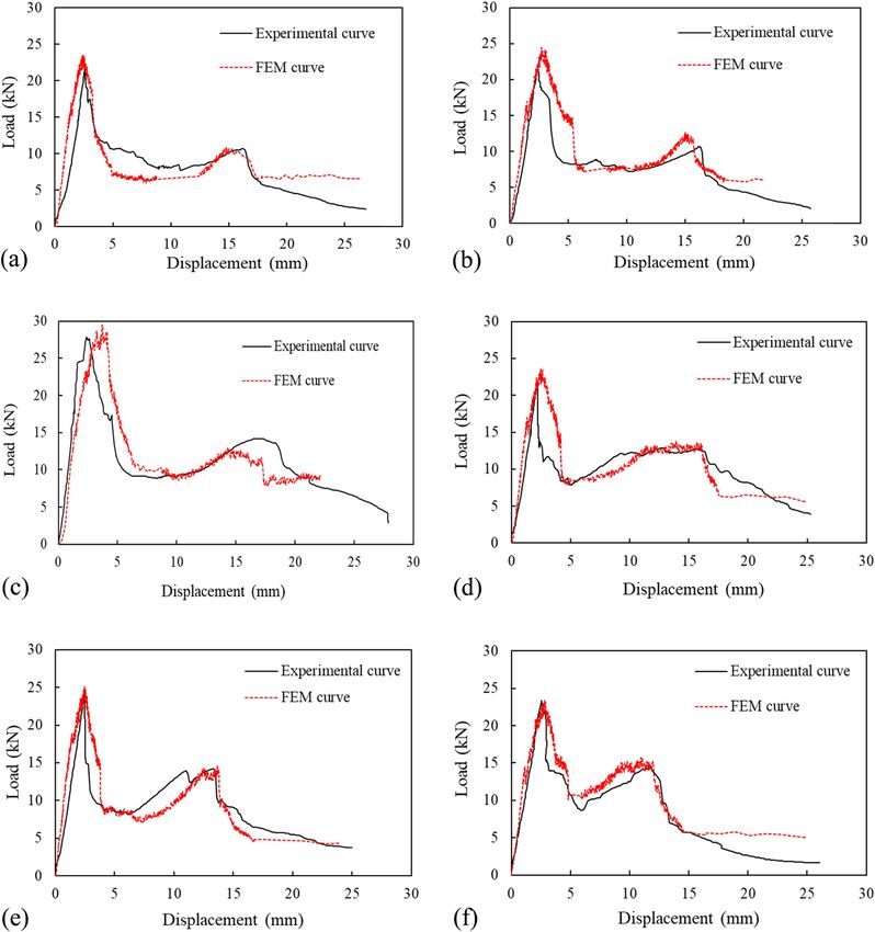
452 Zhilin Chen et al.
sandwich panels with lattice webs. The influences of the Table 2: Mechanical properties of syntactic foams
number of FRP skin layers, syntactic foam density, and
lattice webs and their thickness are analyzed. Moreover, Foam density Compressive strength Young’s modulus
a 3D finite-element (FE) model is developed to conduct a (kg/m3) (MPa)/δ (%) (GPa)/δ (%)
parametric study, with a focus on optimal energy absorp- 450 22.12/3.70 1.00/5.16
tion and crushing load resistance. 480 25.01/3.30 2.18/2.00
Note: δ is the coefficient of variation.
2 Experimental methods 2.2 Test specimen
Sixteen specimens were fabricated to study the quasi-static
2.1 Materials crushing responses, including two synthetic foam panels,
eight GFRP–synthetic foam sandwich panels without webs,
All GFRP–syntactic foam sandwich panels were manu- and six GFRP–synthetic foam sandwich panels with lattice
factured by vacuum-assisted resin infusion. E-glass bidir- webs (Figure 1). The distance between the webs was 75 mm.
ectional woven fabrics and vinyl ester resin were used in All test specimens had the same width (300 mm) and
facesheets and lattice webs. The fiber longitudinal and length (300 mm). The differences between the test speci-
transverse volume fractions were 1:1 and 1:4 for the sheet mens were the number of layers of FRP facesheets and
faces, respectively. The volume fraction ratio for the fiber cross webs, fiber volume fraction of FRP facesheets, and
and resin was 1:1 for the lattice webs. The thickness of densities and heights of the syntactic foams. The sixteen
one layer of GFRP was approximately 0.6 mm, measured specimens are denoted as Sd30, SD30, F44d30, F44D30,
using flat coupons. To determine the material properties F41d30, F21D30, F41D30, F61D30, F41D25, F41D35,
of the GFRP composites, tensile and compressive tests F41D30w2, F41D30w4, F41D30w6, F41d30w4, F41D25w4,
were carried out according to American Society for Testing and F41D35w4. Table 3 lists the characteristics of the test
and Materials ASTM D 638-14 [39] and ASTM D 695-15 [40], specimens.
respectively. The measured properties of the composite
materials are listed in Table 1.
Macrosphere syntactic foams, supplied by Engineered 2.3 Experimental setup
Syntactic Systems, USA, with densities of 450 and 480 kg/m3
were used in this study. The volume fraction of spheres of The crush strengths of all specimens were evaluated
the foam was 58%. The average sphere diameters of the using a universal testing machine with a capacity of
foams with densities of 450 and 480 kg/m3 were 4.04 and 200 kN. The specimens were fixed between two steel
4.12 mm, while the average wall thicknesses were 0.122 plates with a square hole with a width of 200 mm in the
and 0.150 mm, respectively. For each density, five square center. The steel plates were fixed on two steel I-beams
coupons were tested according to ASTM D 1621-16 [41] to by screws. The specimens were indented by a hemisphe-
obtain the compressive strength and modulus. Table 2 rical-end steel head with a mass of 1.5 kg and a diameter
presents the measured properties of the syntactic foams. of 20 mm. The indentation loading was controlled by
Table 1: Mechanical properties of GFRP
Property Fiber longitudinal–transversal volume fraction
1:1 (%) 1:4 (%)
Longitudinal tensile strength (MPa)/δ 330.6/8.31 291.6/8.9
Transverse tensile strength (MPa)/δ 330.6/8.31 371.8/2.35
Longitudinal tensile modulus of elasticity (GPa)/δ 31.8/6.47 28.2/4.61
Transverse tensile modulus of elasticity (GPa)/δ 31.8/6.47 33.4/5.14
Poisson’s ratio/δ 0.22/4.35 0.15/8.01
Note: δ is the coefficient of variation.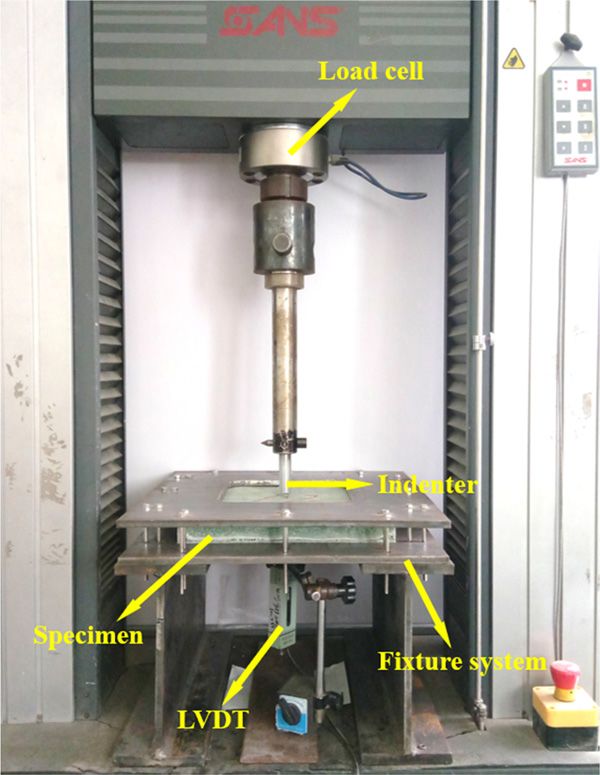
Crushing behaviors of syntactic foam sandwich panels with lattice web 453
Figure 1: Diagram of syntactic foam sandwich panels (1. GFRP sheet faces, 2. Syntactic foam core, 3. Lattice webs). (a) Sandwiches with GFRP
sheet faces. (b) Sandwiches with GFRP skins and lattice webs.
displacement at a rate of 5 mm/min [42]. During the curves and analysis of energy absorptions and variations
testing, the load was recorded by a load cell above the in experimental data as functions of the number of
indenter and a linear variable-displacement transducer FRP layers of facesheets and lattice webs are presented.
was mounted centrally under the specimen to record Our analysis also pertains to the fiber transverse–
the displacement. The time interval for data collection longitudinal volume fraction and syntactic foam density
of the load and displacement was 5 s. The test setup, and thickness.
measurement, and fixture systems are shown in Figure 2.
3.1 Failure modes
3 Results and discussion
Figure 3 shows the test specimens after the quasi-static
The damage propagation and failure modes are identified crushing. In the bare syntactic foam panels, a small
using the test specimens. Subsequently, load–displacement dent with a diameter of 20 mm was observed at the
Table 3: Characteristics of the test specimens
Specimen Number of fiber Fiber longitudinal–transversal Density of the Thickness of the Number of fiber
layers of FRP volume fraction syntactic foam foam core (mm) layers of webs
facesheets (kg/m3)
Sd30 — — 450 30 —
SD30 — — 480 30 —
F44d30 4 1:4 450 30 —
F44D30 4 1:4 480 30 —
F41d30 4 1:1 450 30 —
F21D30 2 1:1 480 30 —
F41D30 4 1:1 480 30 —
F61D30 6 1:1 480 30 —
F41D25 4 1:1 480 25 —
F41D35 4 1:1 480 35 —
F41D30w2 4 1:1 480 30 2
F41D30w4 4 1:1 480 30 4
F41D30w6 4 1:1 480 30 6
F41d30w4 4 1:1 450 30 4
F41D25w4 4 1:1 480 25 4
F41D35w4 4 1:1 480 35 4
Note: In the first column, the first letter, S or F, represents the bare syntactic foam panel or FRP-syntactic foam sandwich panel, respec-
tively; the second letter, d or D, represents the density of the syntactic foam, 450 or 480 kg/m3, respectively; the third letter w represents
the distance between the webs of 75 mm; the first number after F represents the number of fiber layers of FRP facesheets; the second
number after F represents the fiber transversal–longitudinal volume fraction; the two numbers after d or D represent the thickness of the
foam core of 25, 30, and 35 mm; and the last number represents the number of fiber layers of webs.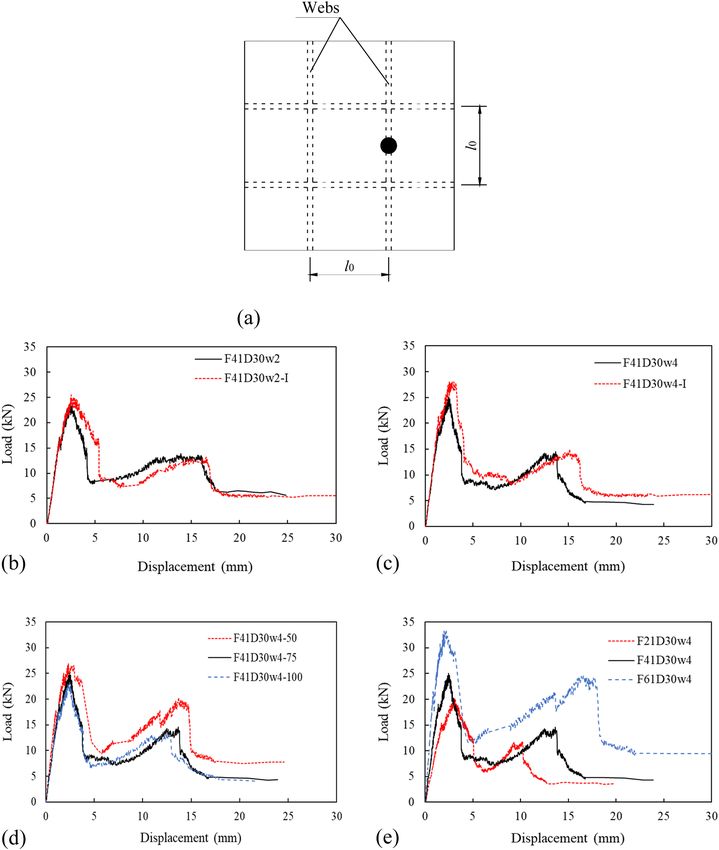
454 Zhilin Chen et al.
(a)
300 R4
28
Specimen
n Steeel plate
10
10 10
400
200
Screw
w Steel plate
p 0
R2
120
I-beam 10
135 135
10
100 200 100
400 300
400
(b)
(c)
Figure 2: Test setup and fixture system (unit: mm). (a) Test setup. (b) Side view of fixture system. (c) Vertical view of fixture system.
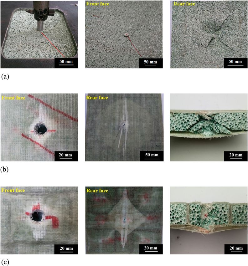
load location; the indenter completely penetrated the shear failure of the foam core dominantly determined the
panel, as shown in Figure 3(a). A crack was formed on failure modes (Figure 3(b)).
the front surface of the syntactic foam panel, which The damages on the front surfaces of the sandwich
then propagated in the 45° direction owing to the specimens with lattice webs were similar to those of the
shear failure of the syntactic foam. On the rear surface specimens without lattice webs. However, the delamina-
of the syntactic foam panel, the damage region was tion zone on the rear surface of the specimen with lattice
wider than that on the front surface, and four diagonal webs had a diamond shape because the debonding between
radial cracks were observed upon the increase in the rear face and foam was controlled by the lattice webs.
applied load. The debonding was further confirmed by the photograph of
In the FRP–syntactic foam sandwich panels, a hole the cross section in Figure 3(c), which reveals the breakages
with a diameter of 20 mm was observed on the front sur- of the fiber and resin on both front and rear faces, including
face accompanied by the breakage of the fiber and resin the shear deformation of the foam core.
around the loading location. The penetration area on the
rear surface was considerably smaller than that on the
front surface. In addition, a circular delamination zone 3.2 Load–displacement curves
with a diameter of approximately 90 mm was observed on
the rear surface. The side view of the cross section shows Typical load–displacement curves of the bare syntactic
that the debonding between the rear face and foam and foam panels and FRP–syntactic foam sandwich panels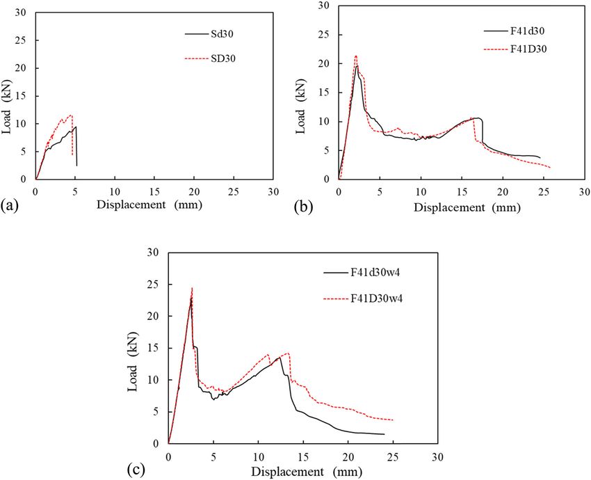
Crushing behaviors of syntactic foam sandwich panels with lattice web 455
Figure 3: Damage of typical specimens. (a) Bare syntactic foam panels (i.e., SD30). (b) FRP–syntactic foam sandwich panels (i.e., F41D30).
(c) FRP–syntactic foam sandwich panels with lattice webs (i.e., F41D30w4).
are shown in Figure 4. The load on the synthetic foam load. The penetration of the top facesheets led to a sharp
panels increased linearly to approximately half of its decrease in load. The plastic phase is associated with the
peak, and several small peaks were generated before crushing of the foam core, propagations of cracks in
the maximum load owing to particle fracture. Brittle the matrix of foams, and breakage and delamination of
failure occurred in the syntactic foam panels after the the GFRP bottom facesheets, which led to continuous
maximum loads were reached. energy dissipation. Further deformation led to the com-
All sandwich panels exhibited four-phase displace- paction of the foam core associated with the crushing of
ment responses: linear-elastic phase, plastic phase, foam macrospheres and extrusion of foam blocks.
compaction phase, and bottom facesheet penetration In the foam compaction phase, the vertical displacement
phase. The load on the sandwich panels increased to its increased with the applied load, and then extrusion of the
peak in the linear-elastic phase, decreased by approxi- foam occurred. Subsequently, the bottom facesheets were
mately 60–70%, and then fluctuated around a sustained penetrated by the load indenter, which led to load reduction.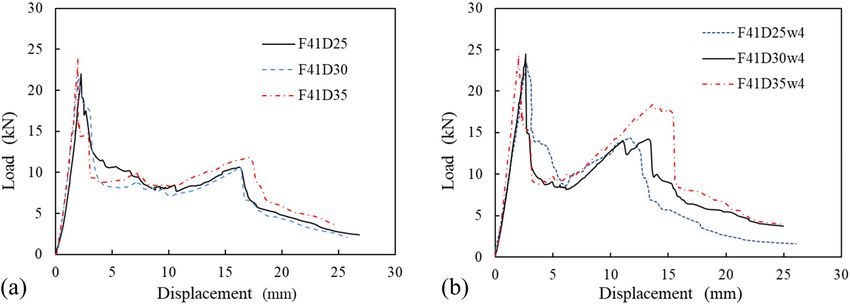
456 Zhilin Chen et al.
Figure 5 shows the influences of the number of FRP
layers of facesheets on the peak load Pmax and stiffness in
linear-elastic phase K1 of the specimens (SD30, F21D30,
F41D30, and F61D30) with the same fiber volume frac-
tions in both transverse and longitudinal directions and
foam densities. For the specimens with the foam density
of 480 kg/m3, when the number of layers of GFRP face-
sheets was increased from 0 to 6, Pmax and K1 increased
by ∼48 to 143% and 27 to 222%, respectively. Increasing the
number of FRP layers contributes to hinder the propagation
of crushing damage in the laminates, leading to enhance
the crushing resistance of sandwich composite panels. The
E values of the specimens with four and six layers of GFRP
facesheets increased by 17 and 26%, respectively, com-
pared to that of the specimen with two layers of GFRP
facesheets (Table 4). However, the increase in number of
GFRP layers of facesheets from two to six did not increase
the specific energy absorption (SEA = energy absorption
per unit mass) of the sandwich panel.
Figure 6 shows the influences of the fiber transverse–
longitudinal volume fraction on the Pmax and K1 values of
the specimens (F41d30, F44d30, F41D30, and F44D30)
with the same number of GFRP layers. Pmax and K1 of
F41d30 were 20 and 17% higher than those of F44d30,
Figure 4: Typical load–displacement curves. (a) Bare syntactic foam while Pmax and K1 of F41D30 were 18 and 14% higher than
panels. (b) FRP–syntactic foam sandwich panels. those of F44D30, respectively. E and SEA of F41d30 were
∼30% higher than those of F44d30, while E and SEA of
The energy absorption capacity E is calculated using F41D30 were ∼8% higher than those of F44D30. The
the classical relation: higher fiber volume fraction in both transverse and long-
Δst itudinal directions of the facesheets led to lower peak
E= ∫ P dΔ , (1) load, stiffness, and energy absorption. This is attributed
0 to the lower bond force transfer between fibers.
where P is the applied load, Δ corresponds to the displa-
cement history, and Δst corresponds to the displacement Table 4: Summary of test matrix and results
at the start of the foam compaction phase.
Specimen m (g) Pmax (kN) K1 (kN/mm) E (J) SEA (J/kg)
Sd30 540 9.5 4.32 — —
SD30 576 11.5 4.74 — —
F44d30 886 16.4 8.46 119 134
F44D30 922 18.1 8.70 141 153
F41d30 882 19.6 9.90 154 175
F21D30 747 17.0 6.03 129 173
F41D30 918 21.4 9.95 151 165
F61D30 1,089 27.9 15.26 190 175
F41D25 822 22.0 8.93 147 179
F41D35 1,014 23.8 13.34 168 166
F41D30w2 955 21.7 10.02 166 174
F41D30w4 992 24.5 10.14 173 174
F41D30w6 1,028 26.5 10.27 213 207
F41d30w4 957 22.6 9.99 148 155
F41D25w4 883 23.4 9.09 142 161
F41D35w4 1,100 24.3 13.42 184 167
Figure 5: Effect of the number of FRP layers on facesheets.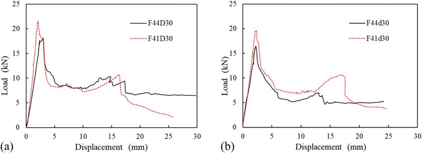
Crushing behaviors of syntactic foam sandwich panels with lattice web 457
Figure 6: Effect of fiber transverse–longitudinal volume fraction. (a) Specimens with foam density 480 kg/m3. (b) Specimens with foam
density 450 kg/m3.
Figure 7 shows the influences of the syntactic foam panel of 21 and 10%, respectively. This is because the syn-
density on the Pmax and K1 values of typical specimens tactic foam with density of 480 kg/m3 has smaller sphere
(Sd30, SD30, F41d30, F41D30, F41d30w4, and F41D30w4). diameter and higher wall thickness of spheres than those of
The increase in syntactic foam density from 450 to 480 kg/m3 syntactic foam with density of 450 kg/m3. The syntactic
led to increases in Pmax and K1 of the bare syntactic foam foam density had small influences on Pmax and K1 of the
Figure 7: Effect of foam density. (a) Bare syntactic foam panels. (b) Sandwich specimens. (c) Sandwich specimens with lattice webs.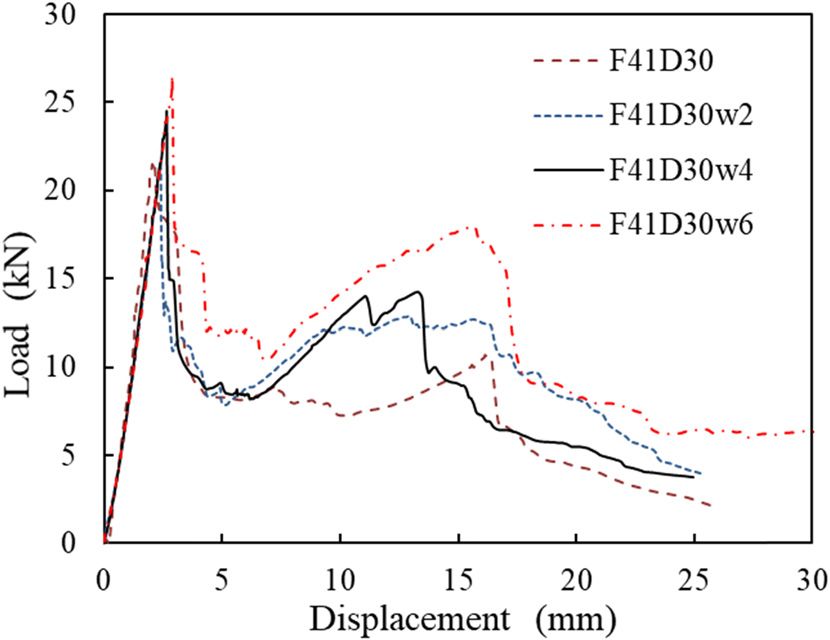
458 Zhilin Chen et al.
Figure 8: Effect of the thickness of the foam core. (a) Sandwich specimens without lattice webs. (b) Sandwich specimens with lattice webs.
sandwich panel. For the specimens without webs, the specimens with thicker foam cores could absorb higher
increase in foam density from 450 to 480 kg/m3 led to small amounts of energy, their SEAs did not significantly change.
decreases in E and SEA owing to the larger plastic deforma- Figure 9 shows the influences of the layer number of
tion in the specimen with the lower foam density. However, lattice webs on the Pmax and K1 values of typical speci-
the increase in foam density increased E and SEA of the mens (F41D30, F41D30w2, F41D30w4, and F41D30w6).
specimen with lattice webs owing to the larger load resis- When the number of layers in the lattice webs was
tance at the higher foam density. The energy absorption increased from 0 to 6, Pmax and K1 increased by 24 and
is related to the load and deformation of the specimen. 3%, while E and SEA increased by 41 and 26%, respec-
Specimens with higher load-carrying capacities and larger tively. It reveals that the lattice webs play an important
plastic deformations usually have higher energy-absorption role in energy absorption in consort with the core. This
abilities. In a specimen with a lower density of the foam indicates that the layer number of lattice webs influenced
core, the syntactic foam has more hollow spheres. The the peak load more significantly than the stiffness. There-
crushing of spheres contributes to a better energy absorp- fore, the increase in number of FRP layers of lattice webs is
tion and increases the deformation. However, the syntactic an effective approach to increase the energy absorption.
foam with a lower density has a lower load-carrying
capacity. The structure of the sandwiches also plays
an important role in the energy absorption. The lattice
webs can significantly improve the debonding charac- 4 FE simulation
teristics of the sandwich panel, which increases the
load-carrying capacity. Hence, the specimens with lat- A 3D FE model was developed using Abaqus Explicit
tice webs and higher foam density had higher energy- 2019. The numerical results were compared to those
absorption capabilities.
Figure 8 shows the influences of the thickness of the
foam core on the Pmax and K1 values of typical sandwich
specimens with and without lattice webs (F41D25, F41D30,
F41D35, F41D25w4, F41D30w4, and F41D35w4). When
the thickness of the foam core was increased from 25 to
35 mm, Pmax and K1 increased by 8 and 49% for the sandwich
specimens without lattice webs and by 4 and 48% for the
sandwich specimens with lattice webs, respectively. The
thickness of the foam core did not considerably affect
the peak load of the sandwich specimens but considerably
increased the stiffness. As the thickness of syntactic foam
core increases, the thickness of the syntactic sandwich panel
increases, which leads to greatly increased moment of inertia
and hence an increase in stiffness. Although the sandwich Figure 9: Effect of the number of FRP web layers.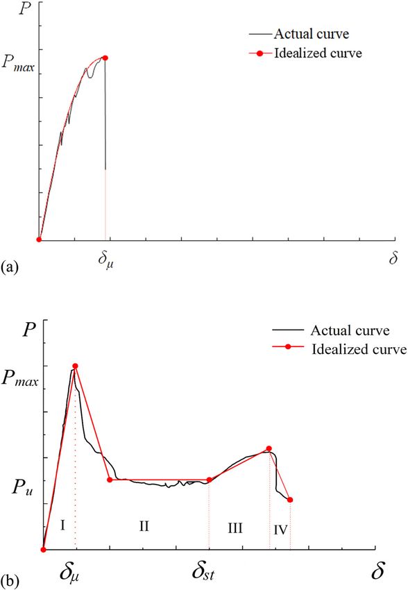
Crushing behaviors of syntactic foam sandwich panels with lattice web 459
Table 5: Elastic properties of GFRP
Properties Fiber longitudinal–transversal volume fraction
1:1 1:4
Tensile strength St,1 (MPa) 330.6 291.6
St,2 (MPa) 330.6 371.8
Compressive strength Sc,1 (MPa) 201 161
Sc,2 (MPa) 201 201
Young’s modulus Ex (GPa) 31.8 28.2
Ey (GPa) 31.8 33.4
Ez (GPa) 9.4 9.4
Poisson’s ratio νxy 0.22 0.15
νxz 0.22 0.15
νyz 0.22 0.15
Shear strength S12 (MPa) 30.6 30.6
S23 (MPa) 30.6 30.6
Shear modulus Gxy (GPa) 3.8 4.1
Gxz (GPa) 13.0 14.5
Gyz (GPa) 13.0 12.3
obtained experimentally. The verified FE model was used in the elastic–plastic model, in which the plasticity mod-
to analyze the effects of the loading position, distance ulus was set to 50% of the elastic modulus. The indenter
between lattice webs, and number of layers of FRP face- was composed of a high-strength steel and thus was mod-
sheets of the sandwich panels with webs. eled as a rigid object with a density of 7,800 kg/m3 and
modulus of 210 GPa.
4.1 Material models
4.2 FE model construction
The material properties of both GFRP and syntactic foam
were obtained using coupon test results. The GFRP face- SC8R, an 8-node continuum shell element with reduced
sheets and webs were assumed to exhibit linear elastic integration and three integration points across each layer’s
behaviors. The input elastic properties for GFRP are listed thickness, was used to model the GFRP facesheets and
in Table 5. The Hashin damage criterion was used to webs, and C3D8R, an 8-node linear brick reduced-integra-
predict the failure of the GFRP. Alhijazi et al. [43] have tion hourglass control element, was used to model the
reviewed the FE analysis of fiber composites, in which foam core and steel indenter. The mesh size is taken as
the Hashin damage criterion was mentioned that it has 5 mm because further decrease in element size almost gen-
the smallest error compared to experimental data. The erates the same results while the computational time
Hashin damage criterion consists of four different damage increases remarkably. In the numerical model, the loading
initiation criteria: fiber tension, fiber compression, matrix speed of the steel indenter is taken as 5 mm/min. The four
tension, and matrix compression. The fracture energy was edges of the sandwich panels were clamped. Surface-to-
defined as the area under the stress–strain curves obtained surface contact elements were used to simulate the
from the mechanical tests in FRP coupons according to
standards ASTM D695-15 [40] and ASTM D2344/D2344M-
16 [44]. The Hashin damage criterion in Abaqus is used Table 6: Fracture energies of GFRP used for simulations [45]
alongside a progressive damage variable, which computes
Gft (N/mm) Gfc (N/mm) Gmt (N/mm) Gmc (N/mm)
the damage state at each increment based on the stress
state and the fracture energy for each failure mode. There- 2.38 5.28 0.424 0.948
fore, four different fracture energy parameters should be
Note: Gft and Gfc are the longitudinal tensile and compressive frac-
defined in Abaqus model. The fracture energy parameters ture energies of GFRP sheets, respectively, and Gmt and Gmc are the
were obtained from ref. [45], as listed in Table 6. The transverse tensile and compressive fracture energies of GFRP
material properties of the syntactic foam were included sheets, respectively.460 Zhilin Chen et al. interface between the steel indenter and sandwich panel, 4.3 Comparison of simulated and as well as the GFRP and foam core. This type of contact experimental results considers slip and separation. Hence, slip/debonding is displayed if either occurs between the GFRP surface and The simulated and selected experimental load–displace- foam surface. Bursi and Jaspart [46] have investigated the ment curves of the syntactic foam sandwich panels are influence of the friction coefficient on the plate connection shown in Figure 10. The simulated curves in Figure 10 response. Their simulated results indicate that the friction show that the model provided a reasonable trend with coefficient in the range of 0–0.5 had a rather limited effect respect to the test data, i.e., the FE analysis could describe on the connection response. Hence, the friction coefficient the overall shapes of the measured load–displacement was set to 0.1 for the contact surface of the GFRP and curves. Table 7 reveals that the simulated peak loads foam core. and stiffnesses are in good agreement with the Figure 10: Comparison of simulated and experimental load–displacement curves. (a) F41D25, (b) F41D30, (c) F61D30, (d) F41D30w2, (e) F41D30w4, (f) F41D25w4.
Crushing behaviors of syntactic foam sandwich panels with lattice web 461
Table 7: Comparison of the initial peak load and stiffness between simulated and experimental results
Specimen Tested peak Simulated peak P ′ max − Pmax
× 100% Tested stiffness K1 Simulated stiffness K ′1 − K1
× 100%
Pmax K1
load Pmax (kN) load P′ max (kN) (kN/mm) K ′ 1 (kN/mm)
F41D25 22.0 22.8 3.6% 8.93 9.67 8.3%
F41D30 21.4 23.4 9.4% 9.95 10.41 4.6%
F61D30 27.9 28.3 1.4% 15.26 13.73 −10.1%
F41D30w2 21.7 22.7 4.6% 10.02 10.69 6.7%
F41D30w4 24.5 24.2 −1.2% 10.14 11.02 8.7%
F41D25w4 23.4 22.7 −3.0% 9.09 9.82 8.1%
experimental values. Most of the simulated stiffnesses attributed to the simulated model, which is stiffer than
are slightly larger than the test results. In the FE model, the actual test specimens.
the four edges of the sandwich panels were assumed to The damage modes of the simulated F41D30 and
be clamped, while the real boundary conditions of test F41D30w2 are shown in Figure 11. The maximum von
specimens were not ideally clamped. Such variation is Mises stress of F41D30 was observed at the center of
Figure 11: Stress contour at the peak load (unit: MPa). (a) Cross section of F41D30. (b) Rear surface of F41D30. (c) Cross section of
F41D30w2. (d) Rear surface of F41D30w2. (e) Numerical progress of F41D30w2. (f) Experimental progress of F41D30w2.462 Zhilin Chen et al. the foam core. On the rear surface of F41D31, the von 4.4 Parametric studies Mises stress reached high levels at the center of the face- sheets and gradually decreased along the radial direc- 4.4.1 Influence of the loading position tion, thereby leading to the crush of the foam core and debonding of the rear facesheets and foam core. The The loading positions of all test specimens were at the maximum von Mises stress of F41D30w2 was observed center of the front surface. The verified FE models were at the bottom facesheets. The rear surface of F41D30w2 used to investigate the responses of the sandwich panels exhibited a diamond shape of the von Mises stress con- when the loads were applied on the middle of a web, as tour in the center region, which indicates that the shown in Figure 12(a). The simulated results indicate debonding of the foam core and rear face was con- that the loading position had an insignificant influence trolled by the lattice webs. on the stiffness of the sandwich panel (F41D30w2 and Figure 12: Influence of varied parameters on the load–displacement curves. Note: In the specimen name, I means the load is applied on the web; and 50, 75, and 100 mean the distance of webs are 50, 75, and 100 mm, respectively. (a) Simulated loading position. (b) Influence of loading position of F41D30w2. (c) Influence of loading position of F41D30w4. (d) Influence of distance of webs. (e) Influence of layers of facesheets of specimens with webs.
Crushing behaviors of syntactic foam sandwich panels with lattice web 463
F41D30w4), as shown in Figure 12(b) and (c). Compared Table 8: Summary of simulated matrix and results
to F41D30w2 and F41D30w4 under the loads applied on
the center of the front surface, the initial peak load Specimen m (g) Pmax K1 E (J) SEA
increased by 7 and 14% for F41D30w2 and F41D30w4 (kN) (kN/mm) (J/kg)
under the loads applied on the web, respectively, as the F41D30w4-50 992 25.9 12.58 216 217.7
local stiffness of the lattice FRP webs was higher than F41D30w4-100 992 22.3 10.88 144 145.2
that of the syntactic foam core. F21D30w4 821 19.4 8.94 107 130.3
F61D30w4 1,163 31.9 19.58 306 263.1
4.4.2 Influence of the distance between lattice webs
5 Conclusion
Three different distances between lattice webs (l0 = 50, 75,
A novel GFRP–syntactic foam sandwich panel with lattice
and 100 mm) in F41D30w4 were investigated. Figure 12(d)
webs, which has the potential to enhance structural per-
shows the load–displacement curves of the F41D30w4
formance and energy absorption ability, was developed.
samples with different distances between lattice webs.
The crushing behaviors and energy absorptions of the
When l0 was above 75 mm, it had insignificant influences
composite sandwich panels were investigated. Moreover,
on the initial peak load and stiffness. The decrease in l0
an optimal design of the syntactic foam sandwich struc-
from 75 to 50 mm led to an increase in initial peak load of
tures as energy absorption members was recommended.
7% and increase in stiffness of 14%.
The results obtained in this study can be summarized as
follows.
4.4.3 Influence of the layer number of facesheets on the (1) The bare syntactic foam panels exhibited shear-domi-
sandwich panels with webs nated failures and were pierced by the indenter. The
GFRP–syntactic foam sandwich panels without webs
The influence of the layer number of facesheets on the exhibited shear failures of the foam cores accompa-
sandwich panel without webs was experimentally inves- nied by the delamination of facesheets and core.
tigated. In addition, the influence of the layer number of Notably, the lattice webs increased the debonding
facesheets on the sandwich panels with webs was inves- strength between the facesheets and foam.
tigated by the verified FE models. Three different num- (2) The peak load and stiffness of the sandwich panel
bers of layers of facesheets (2, 4, and 6) were investigated considerably increased with the number of layers
for the specimens with lattice webs. Figure 12(e) shows of GFRP facesheets, whereas the energy absorption
the load–displacement curves of the specimens with lattice nominally increased. The sandwich specimens with
webs and different layers of facesheets. When the layer thicker foam cores exhibited higher stiffnesses and
number was increased from 2 to 4 and 6, the initial peak energy absorption abilities almost without change
load increased by 25 and 64%, while the stiffness increased in SEA, whereas the syntactic foam density did not
by 78 and 142%, respectively. The test and simulated considerably affect the peak load and stiffness of
results indicate that the increase in layer number of face- sandwich panels. The increase in the number of
sheets is an effective approach to increase the load-car- FRP layers of lattice webs was an effective approach
rying capacity of the sandwich panel with or without webs. to increase the energy absorption of the sandwich
panel without considerable increase in peak load,
assuming the absence of premature debonding.
4.4.4 Recommended optimal structure (3) The verified FE model was used to conduct a para-
meter study. The numerical results of verified FE
The simulated results of the specimens with different dis- model indicated that the loads applied on the web
tances of lattice webs and layer numbers of facesheets of the led to a slight increase in initial peak load in sand-
sandwich panels with lattice webs were listed in Table 8. wich panels compared to the loads applied at the
Based on the experimental and numerical SEA results in center of the panel. The decrease in distance between
Tables 4 and 8, the syntactic foam sandwich panel with lattice webs from 75 to 50 mm led to slight increases
six layers of facesheets and webs, fiber transverse–longitu- in initial peak load and stiffness. The increase in the
dinal volume fraction of 1:1, syntactic foam density of layer number of facesheets on the sandwich panels
480 kg/m3, thickness of foam core of 25 mm, and distance with webs led to considerable increases in the initial
between lattice webs of 50 mm had the maximum SEA. peak load and stiffness.464 Zhilin Chen et al.
(4) Based on experimental and numerical results, the including surface stress effect. Applied Mathematical
optimal design of syntactic foam sandwich structures Modelling, Vol. 89, 2021, pp. 1792–1813.
as energy absorption members was obtained. The [5] Moradi-Dastjerdi, R., K. Behdinan, B. Safaei, and Z. Qin.
Buckling behavior of porous CNT-reinforced plates integrated
structure with six layers of facesheets and webs, fiber
between active piezoelectric layers. Engineering Structures,
transverse–longitudinal volume fraction of 1:1, syn- Vol. 222, 2020, id. 111141.
tactic foam density of 480 kg/m3, thickness of foam [6] Safaei, B., R. Moradi-Dastjerdi, Z. Qin, K. Behdinan, and
core of 25 mm, and distance between lattice webs of F. Chu. Determination of thermoelastic stress wave propaga-
50 mm had the maximum SEA. tion in nanocomposite sandwich plates reinforced by clusters
of carbon nanotubes. Journal of Sandwich Structures &
Materials, 2019, pp. 1–22.
[7] Nakonieczny, D. S., M. Antonowicz, and Z. K. Paszenda.
Funding information: This study was financially sup- Cenospheres and their application advantages in biomedical
ported by the National Natural Science Foundation of engineering – a systematic review. Reviews on Advanced
China (Grant 51578283) and Top Six Talent Projects in Materials Science, Vol. 59, 2020, pp. 115–130.
[8] Rizzi, E., E. Papa, and A. Corigliano. Mechanical behavior of a
Jiangsu Province, China (Grant No. JZ-024). H. GangaRao
syntactic foam: Experiments and modelling. International
and R. Liang acknowledge the support by US-NSF.
Journal of Solids and Structures, Vol. 37, No. 40, 2000,
pp. 5773–5794.
Author contribution: Z. Chen: Formal analysis, valida- [9] Huang, Y. J. Fiber-reinforced syntactic foams. Doctoral
tion, writing – original draft. Y. Zhang: Formal analysis, dissertation, University of Southern California, Los
validation. J. Wang: Investigation, conceptualization, formal Angeles, 2009.
[10] Gupta, N. and S. Sankaran. On the characterisation of syn-
analysis, resources, project administration. H. GangaRao:
tactic foam core sandwich composites for compressive prop-
Writing – review & editing, methodology. R. Liang: Formal erties. Journal of Reinforced Plastics and Composites, Vol. 18,
analysis. Y. Zhang: Performing the experiments. D. Hui: No. 14, 1999, pp. 1347–1357.
Visualization. [11] Zhang, Y., W. Liu, C. Yin, Y. Ma, and L. Wang. Mode II interfacial
fracture characterization of foam core sandwich materials at
Conflict of interest: One of the co-authors of this paper elevated temperatures: The effects of frictional stresses
between the crack edges. International Journal of Solids and
(Prof. David Hui) is an Editor in Chief of Reviews on
Structures, Vol. 193–194, 2020, pp. 28–38.
Advanced Materials Science. [12] Afolabi, L. O., Z. M. Ariff, S. F. S. Hashim, T. Alomayri, S.
Mahzan, K.-A. Kamarudin, et al. Syntactic foams formulations,
Data availability statement: The raw data required to production techniques, and industry applications: A review.
reproduce these findings are available for download from Journal of Materials Research and Technology, Vol. 9, No. 5,
2020, pp. 10698–10718.
http://dx.doi.org/10.17632/9yrs4v4gsr.3#file-265de9f7-2cf2-
[13] Huang, R. and P. Li. Elastic behaviour and failure mechanism in
4dd6-a79b-7d5082d56c6b. The processed data required to epoxy syntactic foams: The effect of glass microballoon
reproduce these findings are available for download from volume fractions. Composites Part B: Engineering, Vol. 78,
http://dx.doi.org/10.17632/9yrs4v4gsr.3#file-1ae0bba6-3496- 2015, pp. 401–408.
4c80-8aaa-7a2516d6008c. [14] Ghosh, D., A. Wiest, and R. D. Conner. Uniaxial quasistatic and
dynamic compressive response of foams made from hollow
glass microspheres. Journal of the European Ceramic Society,
Vol. 36, No. 3, 2016, pp. 781–789.
[15] Hu, G. and D. Yu. Tensile, thermal and dynamic mechanical
References properties of hollow polymer particle-filled epoxy syntactic
foam. Materials Science and Engineering: A, Vol. 528, No. 15,
[1] Kulpa, M., T. Siwowski, M. Rajchel, and L. Wlasak. Design and 2011, pp. 5177–5183.
experimental verification of a novel fibre-reinforced polymer [16] Lapčík, L., M. Vašina, B. Lapčíková, D. Hui, E. Otyepková, R. W.
sandwich decking system for bridge application. Journal of Greenwood, et al. Materials characterization of advanced fil-
Sandwich Structures and Materials, Vol. 5, 2020, id. 371. lers for composites engineering applications. Nanotechnology
[2] Hayman, B. and A. T. Echtermeyer. Reduction of strength of Reviews, Vol. 8, 2019, pp. 503–512.
GFRP sandwich panels in naval ships by face sheet holes, [17] Pellegrino, A., V. L. Tagarielli, R. Gerlach, and N. Petrinic. The
cracks and impact damage. Journal of Sandwich Structures mechanical response of a syntactic polyurethane foam at low
and Materials, Vol. 21, No. 5, 2019, pp. 1621–1653. and high rates of strain. International Journal of Impact
[3] Yuan, C. Crushing responses and design of CF/EP composite Engineering, Vol. 75, 2015, pp. 214–221.
structures. Doctoral dissertation, University of Sydney, [18] Gupta, N., R. Ye, and M. Porfiri. Comparison of tensile and
Sydney, 2018. compressive characteristics of vinyl ester/glass microballoon
[4] Sahmani, S. and B. Safaei. Large-amplitude oscillations of syntactic foams. Composites Part B: Engineering, Vol. 41,
composite conical nanoshells with in-plane heterogeneity No. 3, 2010, pp. 236–245.Crushing behaviors of syntactic foam sandwich panels with lattice web 465
[19] Yuan, J., Z. An, and J. Zhang. Effects of hollow microsphere [33] Mitra, N. and B. R. Raja. Improving delamination resistance
surface property on the mechanical performance of high capacity of sandwich composite columns with initial face/core
strength syntactic foams. Composites Science & Technology, debond. Composites Part B: Engineering, Vol. 43, 2012,
Vol. 199, 2020, id. 108309. pp. 1604–1612.
[20] Marur, P. R. Numerical estimation of effective elastic moduli [34] Wang, B., G. Zhang, S. Wang, L. Ma, and L. Wu. High velocity
of syntactic foams. Finite Elements in Analysis and Design, impact response of composite lattice core sandwich struc-
Vol. 46, No. 11, 2010, pp. 1001–1007. tures. Applied Composite Materials, Vol. 21, 2014,
[21] Yu, M., P. Zhu, and Y. Ma. Global sensitivity analysis for the pp. 377–389.
elastic properties of hollow spheres filled syntactic foams [35] Li, B., Y. Liu, and K. Tan. A novel meta-lattice sandwich
using high dimensional model representation method. structure for dynamic load mitigation. Journal of
Computational Materials Science, Vol. 61, 2012, pp. 89–98. Sandwich Structures & Materials, Vol. 21, No. 6, 2019,
[22] Panteghini, A. and L. Bardella. On the compressive strength of pp. 1880–1905.
glass microballoons-based syntactic foams. Mechanics of [36] Bai, X., Z. Zheng, and A. Nakayama. Heat transfer performance
Materials, Vol. 82, 2015, pp. 63–77. analysis on lattice core sandwich panel structures.
[23] Zeltmann, S. E., B. Chen, and N. Gupta. Thermal expansion and International Journal of Heat & Mass Transfer, Vol. 143, 2019,
dynamic mechanical analysis of epoxy matrix–borosilicate id. 118525.
glass hollow particle syntactic foams. Journal of Cellular [37] Wang, J., H. GangaRao, M. Li, R. Liang, and W. Liu. Axial
Plastics, Vol. 54, No. 3, 2018, pp. 463–481. behavior of columns with glass fiber-reinforced polymer
[24] Moradi-Dastjerdi, R., K. Behdinan, B. Safaei, and Z. Qin. Static composite shells and syntactic foam core. Journal of
performance of agglomerated CNT-reinforced porous plates Composites for Construction, Vol. 23, No. 2, 2019,
bonded with piezoceramic faces. International Journal of id. 04018083.
Mechanical Sciences, Vol. 188, 2020, id. 105966. [38] Wagih, A., P. Maimí, N. Blanco, and J. Costa. A quasi-static
[25] Safaei, B. The effect of embedding a porous core on the indentation test to elucidate the sequence of damage events in
free vibration behavior of laminated composite plates. low velocity impacts on composite laminates. Composites
Steel and Composite Structures, Vol. 35, No. 5, 2020, Part A: Applied Science and Manufacturing, Vol. 82, 2016,
pp. 659–670. pp. 180–189.
[26] Papa, E. and E. Rizzi. Mechanical behaviour of a syntactic [39] ASTM International. ASTM D638 Standard test method for
foam/glass fibre composite sandwich: Experimental results. tensile properties of plastics, ASTM International,
Structural Engineering and Mechanics, Vol. 12, No. 2, 2001, West Conshohocken, PA, USA, 2014.
pp. 169–188. [40] ASTM International. ASTM D695 Standard test method for
[27] Kumar, S. A. and K. S. Ahmed. Compression behavior and compressive properties of rigid plastics, ASTM International,
energy absorption capacity of stiffened syntactic foam core West Conshohocken, PA, USA, 2015.
sandwich composites. Journal of Reinforced Plastics and [41] ASTM International. ASTM D1621 Standard test method for
Composites, Vol. 32, No. 18, 2013, pp. 1370–1379. compressive properties of rigid cellular plastics, ASTM
[28] Salleh, Z., M. M. Islam, J. A. Epaarachchi, and H. Su. International, West Conshohocken, PA, USA, 2016.
Mechanical properties of sandwich composite made of syn- [42] Othman, A., S. Abdullah, A. K. Ariffin, and N. A. N. Mohamed.
tactic foam core and GFRP skins. AIMS Materials Science, Investigating the quasi-static axial crushing behavior of
Vol. 3, No. 4, 2016, pp. 1704–1727. polymeric foam-filled composite pultrusion square tubes.
[29] Zhang, H., C. Gao, H. Li, F. Pang, T. Zou, H. Wang, et al. Materials and Design, Vol. 63, 2014, pp. 446–459.
Analysis of functionally graded carbon nanotube-reinforced [43] Alhijazi, M., Q. Zeeshan, Z. Qin, B. Safaei, and M. Asmael.
composite structures: A review. Nanotechnology Reviews, Finite element analysis of natural fibers composites: A review.
Vol. 9, 2020, pp. 1408–1426. Nanotechnology Reviews, Vol. 9, 2020, pp. 853–875.
[30] Potluri, P., E. Kusak, and T. Reddy. Novel stitch-bonded [44] ASTM International. ASTM D2344/D2344M Standard test
sandwich composite structures. Composite Structures, Vol. 59, method for short-beam strength of polymer matrix composite
2003, pp. 251–259. materials and their laminates, ASTM International,
[31] Mines, R. A. W., C. M. Worrall, and A. G. Gibson. Low velocity West Conshohocken, PA, USA, 2016.
perforation behaviour of polymer composite sandwich panels. [45] Nunes, F., J. R. Correia, and N. Silvestre. Structural behavior of
International Journal of Impact Engineering, Vol. 21, No. 10, hybrid FRP pultruded beams: Experimental, numerical and
1998, pp. 855–879. analytical studies. Thin-Walled Structures, Vol. 106, 2016,
[32] Karahan, M., N. Karahan, H. Gul, and J. Ivens. Quasi-static pp. 201–217.
behavior of three-dimensional integrated core sandwich [46] Bursi, O. S. and J. P. Jaspart. Basic issues in the finite element
composites under compression loading. Journal of Reinforced simulation of extended end plate connections. Computers &
Plastics and Composites, Vol. 32, No. 5, 2013, pp. 289–299. Structures, Vol. 69, 1998, pp. 361–382.You can also read