Feynan Decentralised Wastewater Treatment Plant - Operation & Maintenance Manual - BORDA ...
←
→
Page content transcription
If your browser does not render page correctly, please read the page content below

Released 2019

Feynan Decentralised
Wastewater Treatment Plant
Operation & Maintenance Manual
Feynan Decentralised
Wastewater Treatment Plant
Operation & Maintenance Manual

  ECOHOTELS

                     Ahmad Shabatat & Sons Co.
Published by
Deutsche Gesellschaft für
Internationale Zusammenarbeit (GIZ) GmbH

Registered offices:
Bonn and Eschborn, Germany

Decentralized Wastewater Management for Adaptation
to Climate Change in Jordan (ACC Project)
P.O. Box 92 62 38, Amman 11190, Jordan
T: +962 6 5682915
E: jens.goetzenberger@giz.de , hesham.asalamat@giz.de
I: www.giz.de , www.dwm-acc-jordan.net

September 2019

Photo credits
BORDA

Authors
Anas Abu Khalaf/ BORDA, Sophia von Dobschütz/ BORDA

Editors
Georg Schaumberger/ BORDA, Hesham Asalamat/ GIZ

Coordinator
Jens Götzenberger/ GIZ

On behalf of the
German Federal Ministry for Economic Cooperation and Development
(BMZ)

Table of Contents

1.0 Introduction..............................................................................................................................................................3
    1.1 Why an O&M Manual is required?....................................................................................................................3
    1.2 How to use this manual?.....................................................................................................................................4
2.0 DWWTP description................................................................................................................................................5
    2.1 Process Design....................................................................................................................................................6
3.0 Modules Flow Process...............................................................................................................................................7
    3.1 Biogas Digester...................................................................................................................................................7
    3.2 Anaerobic Baffled Reactor ABR..........................................................................................................................8
    3.3 Floating Valve.....................................................................................................................................................9
    3.4 Vertical Flow Constructed Wetland (VFCW)....................................................................................................10
    3.5 Solar Pump.......................................................................................................................................................11
    3.6 Irrigation network system..................................................................................................................................11
4.0 System start-up procedure.......................................................................................................................................13
    4.1 Treatment Modules Startup...............................................................................................................................13
    4.2 Irrigation Network Controller programming....................................................................................................15
5.0 Tasks to be performed.............................................................................................................................................19
    5.1 Biogas digester tasks..........................................................................................................................................20
        Task 1: Check for grease and scum accumulation..............................................................................................20
        Task 2: Cleaning biogas stove burner................................................................................................................21
        Task 3: Check for biogas leakage at biogas supply pipeline................................................................................22
        Task 4: Desludging the biogas digester dome....................................................................................................23
    5.2 Anaerobic Baffled Reactor tasks.........................................................................................................................24
        Task 5: Check of free wastewater flow...............................................................................................................24
        Task 6: Stir the scum in the anaerobic reactors (Biogas digester +ABR).............................................................25
        Task 7: Remove the scum in the ABR chambers...............................................................................................26
        Task 8: Check the sludge level of the biogas digester and ABR..........................................................................27
        Task 9: Desludging ABR chambers...................................................................................................................28
    5.3 Floating valve tasks...........................................................................................................................................29
        Task 10: Cleaning the floating valve chamber and pipes....................................................................................29
        Task 11: Replacing the flexible hoses in the floating valve chamber...................................................................30
    5.4 Solar pump tasks...............................................................................................................................................31
        Task 12: Cleaning the solar pump chambers.....................................................................................................31
        Task 13: Check the function of the solar pump................................................................................................32
    5.5 Vertical Flow Constructed Wetland tasks..........................................................................................................33
        Task 14: Check and adjust the pile up pipe level in the VFCW........................................................................33
        Task 15: Check the colour of the outflow.........................................................................................................35
        Task 16: Check the surface of the reed basins (stagnant water)..........................................................................36
        Task 17: Check the colour of the reed plants (Green or yellow)........................................................................37
        Task 18: Reeds harvesting and removal of dead leaves.......................................................................................38
        Task 19: Check and clean VFCW distribution system (blockage of holes)........................................................39
        Task 20: Checking and cleaning of VFCW drainage pipes................................................................................40
    5.6 Valves adjusting tasks........................................................................................................................................41
        Task 21: Adjusting of recirculation valve (no.2)................................................................................................41
        Task 22: Open/Close valve no.1........................................................................................................................42
        Task 23: Cleaning of the pipe between the Irrigation tank and the DWWTP...................................................43
        Task 24: Clean the existent solar panels with the treated wastewater.................................................................44
    5.7 Irrigation network tasks....................................................................................................................................45
        Task 25: Flushing the Irrigation system.............................................................................................................45
        Task 26: Controller Quick Check.....................................................................................................................46
        Task 27: Setting and modifying the irrigation schedule.....................................................................................47
        Task 28: Cleaning of the filtering medium........................................................................................................48
        Task 29: Cleaning the Solenoid Valve...............................................................................................................49
        Task 30: Cleaning of the bubblers.....................................................................................................................50
6.0 Emergency overflow cases........................................................................................................................................51
7.0 Troubleshooting......................................................................................................................................................53
8.0 Quality Monitoring.................................................................................................................................................59
9.0 Don’ts List...............................................................................................................................................................60
10.0 Activity and Time Checklists / Maintenance plan..................................................................................................61
    10.1 Overview of Tasks...........................................................................................................................................64
List of Abbreviations

 ABR           Anaerobic Baffled Reactor

 ACC           Decentralized Wastewater Management for Adaptation
               to Climate Change in Jordan
 BORDA         Bremen Overseas Research and Development
               Association
 DWWM          Decentralized Wastewater Management

 DWWTP         Decentralized Wastewater Treatment Plant

 EMFM          Electro-Magnetic Flowmeter

 ETO           Reference Evapotranspiration

 GIZ           Deutsche Gesellschaft für Internationale
               Zusammenarbeit
 HRT           Hydraulic Retention Time

 ME            Middle East

 O&M           Operation and Maintenance

 RSCN          Royal Society for the Conservation of Nature

 TSE           Treated Sewage Effluent

 VFCW          Vertical-Flow Constructed Wetland

 WW            Wastewater

 ELCB          Earth-leakage circuit breaker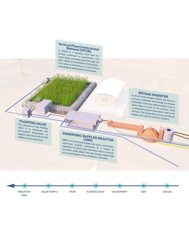
List of Figures

Figure 1: Conceptual drawing of a fixed-dome (left side) and flow principle of the digester.................. 7
Figure 2: ABR conceptual design and its flow principle........................................................................ 8
Figure 3: Float-valve chamber AutoCAD design................................................................................... 9
Figure 4: VFCW 3D design model..................................................................................................... 10
Figure 5: Solar pump elements identification...................................................................................... 12
Figure 6: Schematic Diagram of Bubbler Irrigation System................................................................ 12
Figure 7: Setting date and time........................................................................................................... 15
Figure 8: Setting program starting time.............................................................................................. 15
Figure 9: Setting station run times...................................................................................................... 16
Figure 10: Setting days to water.......................................................................................................... 16
Figure 11: Treatment system layout (top view) shows the valves location............................................ 41
Figure 12: Irrigation tank drawing shows the location of valve no.1.................................................... 42
Figure 13: Drawing shows the recirculation pipe................................................................................ 43
Figure 14: AutoCAD drawing that shows the layout of the Ecolodge and the treatment system......... 51

List of Tables

Table 1: Illustrated daily run time at different growing seasons........................................................... 17
Table 2: Illustrate the accompanying run time of irrigation frequency at different growing seasons..... 17
Table 3: Troubleshooting activities for all treatment modules............................................................. 53
Table 4: Sampling frequency for (small population) treatment plants as per JS 893/2006................... 59
Table 5: Tasks and frequency of each module..................................................................................... 61
Table 6: EMFM readings table........................................................................................................... 62
Table 7: Biogas digester feeding list.................................................................................................... 63
Table 8: Maintenance tools list........................................................................................................... 65
1.0 Introduction
The GIZ Project “Decentralised Wastewater Management for Adaptation to Climate Change
in Jordan” (ACC-Project) is supporting partner organizations in decentralized wastewater
management (DWWM) as a measure for adaptation to climate change. The project aims
to promote robust, easy-to-build, easy-to-operate, proven, flexible and sustainable wastewa-
ter treatment technologies. Within the scope of the ACC-Project, an integrated concept for
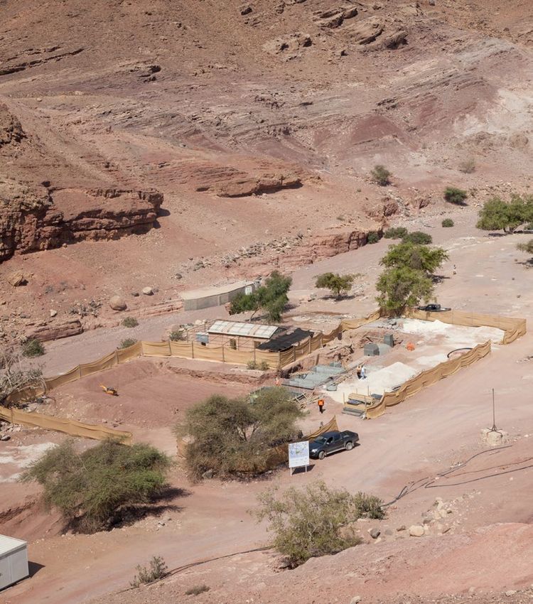
DWWM is implemented for demonstration purposes at Feynan Ecolodge located in Dana
Biosphere Reserve south of Jordan.
The Operation and Maintenance (O&M) Manual was was jointly developed by BORDA and
GIZ and is supposed to support and facilitate day-to-day operational tasks to provide smooth
functioning of the treatment system at Feynan Ecolodge.
1.1 Why an O&M Manual is
required?
• Steady functioning of the System
• Continuous high Treatment
Performance
• Longer Lifetime System
Expectancy
• Social Benefits: Prevent Possible
Complaints on Malfunctioning
Effects
3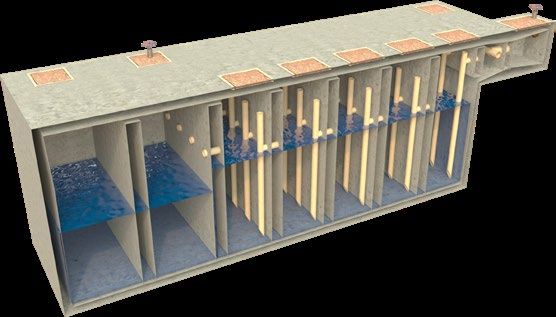
1.2 How to use this manual?
This manual is intended to be used by the
operator of the Decentralised Wastewater
Treatment Plant (DWWTP). The tasks are
simple and require only basic training. Nev-
ertheless, regular Operation and preventative
maintenance is mandatory and critical to
ensure continuing high performance of the
treatment system.
Each operational task is addressed in terms of
where and when it will occur, why it is needed
and how the task should be performed.
The given guidelines shall support the oper-
ator to keep the system working efficiently.
However, changes in quantity or quality of the
WW influent or drastic changes in the climate
may also affect the DWWTP’s performance,
mainly by extending or shortening the inter-
vals between the operational tasks.

                                                 4
2.0 DWWTP description

5
2.1 Process Design

                 Kitchen                             Black Water & Food Waste                           Grey Water

       Wadi                                         Biogas Digester

                           Overflow

     Cesspit
                                     Solar Pump 2

                                                     Solar Pump 1

                                                               Anaerobic Baffled Reactor (ABR)

  Holding Tank                                                                   Floating Valve

                                                                    Vertical Flow Constructed Wetland (VFCW)

                                                                             Recirculation

   Irrigation

                                                                                                                     6
3.0 Modules Flow Process 3.1 Biogas Digester Biogas digesters are used as primary treatment modules instead of regular settlers in order to use the generated biogas instead of releasing it into the environment. Figure 1: conceptual drawing of a fixed-dome (left side) and flow principle of the digester The following elements are to be distinguished for the infrastructure: 1. Inlet: Part of the system where the organic material is fed into the digester in addition to the WW influent that derives from the toilets and the kitchen. 2. Digester: (Underground) part of the system where the organic material (WW mixed with the organic solid waste) is exposed to methane-producing bacteria under anaerobic conditions. 3. Outlet: Part of the system where the digested organic material is leaving the digester. During the digestion process methane gas is generated in the digester and due to the rising pressure in the digester the pre-treated WW is pushed out of the digester through the outlet. 4. Expansion chamber: Part of the system where the pre-treated WW is replaced by gas inside the digester is stored, which also maintains the pressure to push the gas out of the digester. The following termini relate to the inputs and outputs of the digestion process: • Slurry: The material fed into the digester (Wastewater mixed with organic solid waste). • Sludge: The material settling at the bottom of the digester and in the expansion chamber. • Swimming layer: Material forming and accumulating in the digester on top of the slurry. • Scum: floating layer at the top which contain dirt and gas bubbles. The inflow (in the case of Feynan blackwater originating from sewer pipes and organic solid waste) is totally mixed at the inlet manhole before getting in contact with the old substrate and the sludge retaining in the digester. Organic and inorganic settleable solids sediment to the bottom forming a sludge layer that must be removed after some years. Besides the mechanical removal of solids by sedimentation, anaerobic bacteria degrade organic pollutants and the sludge is digested anaerobically. During this process biogas is generated which accumulates in the top of the dome. The accumulating gas pushes the water from the digester into the expansion chamber. If gas is released from the dome through the gas valve, the water level raises again in the digester. 7
3.2 Anaerobic Baffled Reactor ABR

The ABR consists of a series of chambers, in which the WW flows upstream. In Feynan case the ABR consists
of 5 equal chambers in series. As mentioned, pipes direct the WW stream between the individual chambers
from top to bottom. At the bottom of each chamber, active sludge is retained. During inflow into the cham-
ber, WW is forced to pass through sludge blanked whereby it is inoculated with the WW organisms, which
decompose the contained pollutants. The increased contact time with the active biomass (sludge) results in
improved treatment. In the first chamber degradable substances are broken down easily while in the following
chambers, decomposition of less degradable substances takes place. The first chamber contains the most sludge
height compared to the following chambers.

Figure 2: ABR conceptual design and its flow principle

                                                                                                           8
3.3 Floating Valve
From the outlet of the ABR, the wastewater is pumped into the floating valve chamber using a pump run by
solar energy. The floating valve chamber is filled constantly with wastewater until a certain limit (2 m3). At
the maximum water level, the floating valve is automatically pushed through the stop limit as well as through
its own weight down. As a result, the amount of wastewater between maximum and minimum water level
in the chamber is pushed in one batch into the distribution chamber. From the distribution chamber, the
wastewater flows in one batch through two equal sloped pipes fixed at the bottom of the chamber into the
two VFCW beds.
DN 110 HDPE DN 160 UPVC
From Solar Pump 1 Overflow pipe
Distribution
Chamber
Pile-up Pipe
Pile-up Pipe
Drain Purpose
WL
DN 160 uPVC
to VFCW
BLINDING CONCRETE SLOPE DN 160 uPVC
Drain Siphon
SLAB ON GRADE AS PER STRUCTURE
Syphon & Distribution Chambers to VFCW
100mm BLINDING
SECTION A-A TWO LAYERS COMPACTED FILL
150 mm FOR EACH
Figure 3: Float-valve chamber AutoCAD design
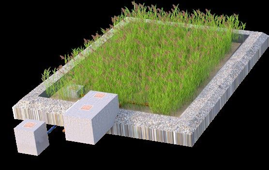
93.4 Vertical Flow Constructed Wetland (VFCW)
The VFCW is a natural treatment system or eco-technology referred to as ‘constructed wetlands’. The VFCW
serves the purpose of treating and recycling wastewater in a sustainable way through utilizing natural micro-
bial processes to transform the pollution in the water into gases, minerals and humus. Once established it is
a very stable habitat which does most of the processes without any required input from the operator. Even
high fluctuation in the inflow in relation to volume and concentration show only little or no influence on the
process and performance of the system. The hot climate in the ME and the nutrient load in the wastewater
cause a rapid growth of the reed plants, which enhances the treatment process (strong root systems, higher
biological processes and greater supply of oxygen) but requires also harvesting of the accumulated biomass
on the filter surface.
Figure 4: VFCW 3D design model
After the pre-treated wastewater is flushed from the floating valve to the VFCW basins, it is distributed on
the VFCW basin surface through perforated distribution pipes. The wastewater percolates then vertically
through the filter layer to the bottom drain pipes. This leads to a forced dewatering, drying, aeration and
mineralization of the organic solids. The bottom drains are connected to the two header drains which will
end in the drainage control manhole.
103.5 Solar Pump
The wastewater treatment system in Feynan runs by the automatic operation of the floating valve and on solar
energy (solar pumps 1 and 2). The solar pumps operate once solar energy is available (sun light) and enough
water is in the pump chambers.
The solar pumping system includes several devices: pump, controller unit, switch box, charge controller,
pressure switch and all required accessories and equipment to regulate the flow.
There are two pumps installed in the system:
Solar pump 1:
Function: the outflow of the ABR flows on gravity into solar pump 1st chamber. The solar pump is feeding
continuously the effluent of the ABR into the floating valve shaft chamber while sunlight is available.
Purpose: to lift the wastewater into another treatment module which is the VFCW via the floating valve.
Solar pump 2:
Functions: the treated sewage effluent (TSE) as an outflow from the VFCWs, is collected through the drainage
network of the VFCW basins and flows into an underground pumping station by gravity. From this solar
pump 2nd chamber the TSE is pumped by solar pump 2 to the irrigation storage tank which is located in
the mountains in the west direction of the lodge.
By opening the manual valves after the irrigation tank to the inflow of the ABR, up to 100% re-circulation
can be achieved. For re-circulation purpose, the TSE flows by gravity from the irrigation storage tank through
a pipe back to the mixing manhole up-flow the ABR.
Purpose:
• Re-circulate the WW from the VFCW outlet to the ABR inlet via the irrigation storage tank (pumped
from solar pump 2 to the irrigation tank; then running on gravity to the inlet of the ABR) in order to
achieve further nitrogen removal in the ABR.
• Pump the treated WW to the irrigation storage tank at a higher point in order to reuse the treated waste-
water for the irrigation of the native trees, and for cleaning of the lodge’s solar panels in order to maintain
their efficiency. The TSE is to be taken from the irrigation storage tank via a valve.
3.6 Irrigation network system
The irrigation network system is responsible to distribute the TSE from the irrigation storage tank via the
network by gravity to irrigate the targeted native trees which is controlled by a programmed automatic con-
troller. The network covers the whole area surrounding the ecolodge with an average water demand of 3 m3/
day for irrigation.
116
7
16
17
7
12 kWatt
11
18
5
4
3
2
1
TM03 4232 1013
Fig. 10 SQFlex Solar with backup batteries
Pos. Description
1 SQF pump
2 Submersible drop cable
3 Cable clips Not Included in offer
4 Straining wire Not Included in offer
5 Wire clamps Not Included in offer
6 Solar panels Not Included in offer
7 Support structure Not Included in offer
11 CU 903 SQFlex control unit
12 IO 50 SQFlex switch box
16 Charge controller
17 Batteries Not Included in offer
18 Pressure switch
Figure 5: Solar pump elements identification Figure 6: Schematic Diagram of Bubbler Irrigation System
124.0 System start-up procedure This chapter explains how to run the system for the first time. This procedure is considered as one of the most critical procedures that relate to the DWWTP, due to the sensitivity of the anaerobic processes inside the treatment units (i.e. Biogas digester and ABR). In addition, construction faults, pipe leakages and gas/water tightness of the units can be explored during the commissioning phase. 4.1 Treatment Modules Startup Biogas Digester: The biogas digester receives blackwater from the ecolodge’s toilets, kitchen wastewater, food waste, as well as papers and cardboards after shredding. The methane gas production needs normally between 25-40 days to be generated. Hence, to reduce the time needed to initiate gas production in Feynan, sludge that is stored in the existing septic tank is pumped into the digester. This inoculation with active biomass enhances the bacterial digestion environment which will speed up the gas production. ABR: A newly constructed and empty ABR requires a start-up period of several months to reach its full treatment capacity since the slow growing anaerobic biomass first needs to be established in the reactor. To reduce start-up time, the ABR shall be inoculated with anaerobic bacteria, e.g., by adding sludge from the existing septic tank or adding fresh cow or animals’ dung. The added stock of active bacteria will multiply and adapt to the incoming WW. In principle, if none were possible to be added, then it is advantageous to start with a quarter of the daily flow and then slightly increase loading rates over three months, allowing the bacteria to multiply before suspended solids are washed out. Because of the delicate ecology inside the reactor, care should be taken not to discharge harsh chemicals into the ABR especially during the commissioning phase. VFCW: The VFCW needs enough water to avoid loss of reed plants after plantation phase. For that reason, a constant water level (5 cm below filter surface) must be maintained in the basins during the first weeks (normally 6 weeks) of plantation phase especially in the springtime or till it is needed on later stages. After that, the water level in the VFCW basin should be reduced every two weeks by drilling holes (5 cm lower) into the pile-up pipe, according to root growth of young reed plants. Young reed plants are vulnerable to dehydration and drowning. During sowing or planting they require damp soil with water around 5 cm below the surface for the first weeks of planting. After young shoots have sprouted, water levels can be reduced, but the top ⅓ of the plants must be above the water surface. Older reeds can ‘breathe’ in deeper water, the preferable water depth is from 5 cm – 1 m. After the reeds are grown and in good condition, then the pile-up pipe can be removed. 13
14
4.2 Irrigation Network Controller programming

The irrigation network has many characteristics that should be adjusted to work properly

A)- Setting Current Date and Time

The Set Current Date and Time dial position allows you to set the current date and time in your I-CORE
controller.
1. Turn the dial to the SET CURRENT DATE/TIME position.
2. The year will be flashing in the display. Use the + / - button to
change the year. Press the ► button to proceed.
3. The month will be flashing. Use the + / - button to change the
month. Press the ► button to proceed.
4. The day will be flashing. Use the + / - button to change the day.
Press the ► button to proceed and set the time.
5. Use the + / - button to select AM, PM, or 24 HR. Press the ►
button.
6. Use the + / - button to set the hour. Press the ► to set the minutes.
Use the + / - button to change the minutes until they are correct. The
correct date and time have now been set. Always return the dial to the
                                                                           Figure 7: Setting date and time
RUN position when you are finished programming the controller.

B)- Setting Program Start Times

The Set Program Start Times mode allows you to program start times for each of the four programs (A, B, C,
or D) independently. Up to eight start times per day can be set for each program.
1. Turn the dial to the SET PROGRAM START TIMES position.
2. Program A and start time 1 will be displayed. If necessary, you can select Program B, C, or D by pressing
the PRG button.
3. The program start time will be flashing. Use the + / - button to change the start time. The time will change
in 15-minute increments. Press the ► button to select an additional start time if you would like more than
one watering cycle per day to occur for that program. Programs A, B, C have eight start times per day, while
program D has 16 start times. Press the PRG button to change
between programs A, B, C, and D to assign a start time to the par-
ticular program.
4. To eliminate a program start time turn the dial to the SET PRO-
GRAM START TIMES position, use the PRG button to select the
program and the ► button to select the start time you would like
to eliminate. Press the + / - button until you reach 12:00 AM. Press
the – button once more and the display will show dashed lines --:--,
indicating no start time.

                                                                           Figure 8: Setting program starting time

15
C)- Setting Station Run Times
(Length of Watering for Each Station)
The Set Station Run Times mode allows you to enter a length of run time for each station assigned to a
program. Each station that has a run time associated with a program will be activated and operate one after
another sequentially with each start time for that program.
1. Turn the dial to the SET STATION RUN TIMES position
2. The display will show the station number and program. Use the
PRG button to select a program
3. Use the + / - button to change the station run time on the display
4. Use the ► button to advance to the next station for which you
would like to enter a run time
5. When finished entering run times, rotate the dial to the RUN
position
Figure 9: Setting station run times
D)- Setting Days to Water
Set Days to Water mode allows you to select days you would like to water for each program independently.
1. Turn the dial to SET DAYS TO WATER position.
2. Program A water days will be displayed. Use the PRG button to select your desired program (A, B, C, or D).
3. Use the ◄ and ► button to change from 1) Specific Days of the Week; 2) Odd Day Watering; 3) Even
Day Watering; or 4) Interval Day Watering. Each program can only be assigned one type of water day option
at a time.
Please note that:
• The Irrigation run time and frequency must be taken from table
1 at different months and seasons.
• The irrigation run time for both solenoid valve is the same.
• The irrigation run time was calculated based on using two bub-
blers of 0.25GPM flow rate for each tree.
• The same irrigation requirements have been assumed for all native
plants surrounding the lodge.
Figure 10: Setting days to water
16Run-times
Table 1: Illustrated daily run time at different growing seasons
Year 1st year 2nd year 3rd year 4th year 5th year 6th year
Irrigation requirement % 25.00 30.00 40.00 55.00 75.00 100.00
Month Eto Run time
mm/day (minute/day)
January 1.6 1 1 2 2 3 4
February 2.4 2 2 3 3 5 6
March 3.3 2 3 3 5 7 9
April 4.6 3 4 5 7 9 12
May 5.8 4 5 6 8 11 15
June 6.5 4 5 7 9 13 17
July 6.9 5 5 7 10 14 18
August 6.3 4 5 7 9 12 17
September 5.0 3 4 5 7 10 13
October 3.2 2 3 3 5 6 8
November 2.0 1 2 2 3 4 5
December 1.5 1 1 2 2 3 4
Table 2: Illustrate the accompanying run time of irrigation frequency at different growing seasons
Year 1st year 2nd year 3rd year 4th year 5th year 6th year
Month IF Run time
(days) (minute/day)
January 9 10 11 15 21 29 38
February 6 10 11 15 21 29 38
March 4 9 10 14 19 26 35
April 3 9 11 15 20 27 36
May 2 8 9 12 17 23 31
June 2 9 10 14 19 26 34
July 2 9 11 15 20 27 36
August 2 8 10 13 18 25 33
September 3 10 12 16 22 30 40
October 4 8 10 14 19 25 34
November 7 9 11 15 20 28 37
December 9 9 11 14 20 27 36
1718
5.0 Tasks to be performed
This chapter covers all tasks that are to be performed on daily/weekly/monthly basis.

                                                  OVERFLOW             BIOGAS
                                                      Tasks 0            Tasks 1, 2, 3, 4

                          IRRIGATION                                                        ABR
                           Tasks 25, 26, 27,                                                 Tasks 5, 6, 7, 8, 9
                              28, 29, 30

                          VALVES                                                            FLOATING VALVE
                           Tasks 21, 22, 23, 24                                                 Tasks 10, 11

                                                  VFCW                  SOLAR PUMP
                                                                            Tasks 12, 13
                                                   Tasks 14, 15, 16,
                                                     17, 18, 19, 20

19
5.1 Biogas digester tasks
Task 1: Check for grease and scum accumulation
Grease accumulation in the biogas digester Grease accumulation in the biogas digester
Where this task should be done?
• At the biogas digester inlet manhole, where mixing of black water and organic waste takes place
• At the expansion chamber outlet manhole
When this task should be done?
• Once every 2 weeks
• Or, in the following cases
‐ There is large quantity of grease or scum observed in the biogas inlet manhole, expansion chamber
or in the next treatment module (ABR)
‐ There is bad odour and overflow of grease from the top of the expansion chamber or ABR
Why this task should be done?
• To allow the required free flow of WW through the treatment system (avoid cloggings)
• To avoid grease or scum entering subsequent treatment modules
• To avoid bad odour in and around treatment system (i.e. Biogas digester and ABR)
How this task should be done?
Step 1
1. Open the inlet manhole cover of the biogas digester and the expansion chamber
Step 2
1. Check for the presence of excess grease or floating solids in the biogas digester and expansion chamber
2. Check whether the WW remains its usual flow (compare the flow with earlier observations relating to
the EMFM recordings)
Step 3
1. Remove the grease and the scum from the biogas digester inlet manhole, expansion chamber using an
appropriate tool (e.g. perforated shovel)
2. Remove all grease from the mentioned chambers and pipes (using flexible stick) prior the ABR cham-
ber
3. Dispose the grease and other waste safely.
4. If an unusual flow is observed, contact a qualified and specialized service company.
20Task 2: Cleaning biogas stove burner
Cleaning of burner ring holes Cleaning of Jet holes
Where this task should be done?
• At the biogas stove burner(s) in the kitchen
When this task should be done?
• Once every month
• In the following cases
‐ There is an inconsistent gas flame
‐ There is corrosion observed on the stove burner
‐ There are signs of corrosion
‐ There are blockages in the stove holes
Why this task should be done?
• To keep the stove efficient by eliminating depositions
• To use the biogas efficiently
How this task should be done?
Step 1
1. Close the biogas supply valve near the biogas stove
Step 2
1. Dismantle the burner(s) of the stove or other biogas appliances as per appliance manual
2. Clean the burner(s) ring and its holes using a brush and if required a needle
3. Clean the jet hole with a needle
4. Sometimes you may also have to dismantle and clean the gas flame regulator valve if it does not turn easily
5. If corrosion is found, remove it with a brush
6. After completion of all the above steps, make sure that every part is properly put together again
7. Open the biogas supply valve near the biogas stove and check the flame
Step 3
1. If you are not satisfied with the performance of the stove, then contact the stove provider
21Task 3: Check for biogas leakage at biogas supply pipeline
Application of soap solution Application of soap solution
Where this task should be done?
• At the on-ground biogas pipelines, from the biogas digester to the appliances.
When this task should be done?
• Once every 4 months as a routine
• Or, in the following cases
‐ There is no steady pressure and flame in the biogas appliances
‐ There is little or no biogas supply
‐ There is gas odour near the biogas pipe line
Why this task should be done?
• To ensure optimum use of biogas
• To avoid leakage of biogas
• To avoid odour of biogas
• To avoid outburst of fire
How this task should be done?
Step 1
1. Prepare a soap solution by mixing water and liquid soap (3:1 mixture) or water and detergent powder
(1 cup water: 1 tea spoon detergent powder)
2. Check the following:
‐ Availability of gas by lighting the appliance (stove etc.)
‐ Whether the main valve at biogas unit is open
‐ The gas pressure by observing the gas meter which is hanged on the kitchen wall
3. Apply this solution on exposed pipes and pipe joints using a paint brush at the place where the gas
leakage is suspected
Step 2
1. Check for the bubbles or foam formation during the application of the soap, which
indicates the location of gas leakage
Step 3
1. If bubbles or foam formation is observed, contact a plumber for rectification work
immediately
2. If biogas leakage continues after rectification, contact a qualified and specialized service company
22Task 4: Desludging the biogas digester
Biogas digester desludging by a truck Digester dome gas valve must be open while desludging
Where this task should be done?
• At the biogas digester
When this task should be done?
• Once every 3 – 4 years, or when desludging is needed; hence when the sludge level exceeds 85 cm
above the bottom of the inlet chamber (Refer to Task 8)
Why this task should be done?
• To keep the efficiency of the sludge settling in the biogas chamber
• To maintain the desired effluent characteristics taking into consideration the required hydraulic reten-
tion time inside the digester. When the biogas digester is full, then the sludge will move to the next
treatment module (ABR) which will affect the expected efficiency of the DWWTP
• To ensure that about 5 cm layer of sludge remains; hence, it gets enough time to be stabilised and to
produce the methane gas efficiently for cooking in the kitchen
• To allow required free flow of wastewater through the entire system (treatment modules) and prevent
clogging
How this task should be done?
Step1:
1. Use the external gas supply for cooking
2. Open the stopper at the gas outlet to avoid damaging the dome, see the picture above
Step2:
1. Open all manholes covers of the biogas digester
2. Insert the desludging vacuum pipe in the inlet manhole chamber
3. De-sludge the digester by using a vacuum truck (recommended) or any other way that is suitable on-site
4. Leave about 10% (about 5 cm) of the sludge at the bottom to maintain the biological process in the digester
5. Make sure to close the manhole tightly
6. Close the stopper at the gas outlet
Step3:
1. Discharge the sludge at a safe disposal facility
235.2 Anaerobic Baffled Reactor tasks
Task 5: Check of free wastewater flow
Obstacles removal from the sewer pipeline Obstacles removal from the sewer pipeline
Where this task should be done?
• Inlets and outlets of all treatment modules at the distribution channels
When this task should be done?
• Once every month, during the peak period (normally in the morning)
• Or, in the following cases
‐ There is overflow in the inspection chamber
‐ There is overflow in the inlet or outlet chambers of any treatment module
‐ There is no wastewater flow in the inspection chambers or treatment modules
Why this task should be done?
• To identify possible blockages in pipes or in any treatment module
• To allow required free flow of wastewater through the entire system (all treatment modules)
• To identify possible damages or leakages
• To prevent mosquito from breeding in the system
How this task should be done?
Step 1
1. Open the manhole cover of the inspection chamber
2. Open the manhole cover at inlet and outlet of each treatment module (biogas digester, ABR, solar
pump chambers and floating valve chamber)
Step 2
1. Check for obstructions like solid materials, floating materials and deposition at all manholes
2. Check whether the wastewater has its usual flow (compare with what was observed in earlier inspec-
tions through flow meter recordings) (see table 6)
Step 3
1. Remove obstructions, if any, using an appropriate tool like shovel/ broom and ensure that all lids are
closed properly to avoid odour
2. If no flow is observed, check whether the system is in use or weather leakages can be observed in and
around the treatment system and if so, contact a qualified and specialized service company
3. If an unusual flow (extremely low, high or much dirtier than usual) is observed, repeat Step 1 and Step
2 for 3 days. If unusual flow continues during observation for 3 days, then contact a qualified and
specialized service company
24Task 6: Stir the scum in the anaerobic reactors (Biogas digester + ABR)
Stir the scum inside the ABR manholes Stir the scum inside the ABR manholes
Where this task should be done?
• At the biogas digester inlet and outlet chamber
• At ABR chambers
When this task should be done?
• Once every month
Why this task should be done?
• To press down the floating scum and heavy particles
• To maintain the efficiency of the modules and avoid transferring heavy particles to the next modules
How this task should be done?
Step1
1. Open the manholes covers
2. Insert the stick into the biogas digester and into the ABR chambers
3. Stir the water until the heavy particles sink down
4. Close the manhole covers
Step 2
1. If few solids were not able to sink down, then remove them using (shove, picking tool)
25Task 7: Remove the scum in the ABR chambers
Scum removal using a perforated shovel Scum removal using a perforated shovel
Where this task should be done?
• At ABR chambers
When this task should be done?
• Once every 6 months
Why this task should be done?
• To maintain the efficiency of the module and to avoid scum accumulation
How this task should be done?
Step 1:
1. Open the manhole covers
2. Insert the perforated shovel or the steel sieving tool in the chambers of the ABR
3. Remove any accumulated grey foam, scum or fat
4. Dispose the accumulated scum, foam or fat into a bucket before final safe disposal
5. Close the manhole covers
26Task 8: Check the sludge level of the biogas digester and ABR
Measuring the sludge level using Sludge level indicator stick
Where this task should be done?
• At the first chamber of the ABR.
• At the inlet manhole of the biogas digester
When this task should be done?
• Once every year
Why this task should be done?
• To identify the sludge level (not more than 50 cm from the bottom) in the first ABR chamber.
• To identify the sludge level (not more than 85 cm from the bottom) in the biogas digester at the inlet
chamber
How this task should be done?
Step1
1. Take a stick and wrap it with cotton material
2. Open the manhole of the first chamber of the ABR or the inlet chamber of the biogas digester
3. Hold the stick vertically in the chamber and all the way down until it reaches the bottom
Step2
1. Take it out and measure how high the accumulated sludge reaches
2. If the sludge level reaches more than 85 cm from the bottom of the biogas digester inlet manhole, then
biogas digester desludging is needed (refer to task 4)
3. If the sludge level reaches more than 50 cm on the stick in the first ABR chamber, then ABR desludg-
ing is needed (refer to task 9)
27Task 9: Desludging ABR chambers.
Desluding the ABR chambers using vacuum truck Desluding the ABR chambers using vacuum truck
Where this task should be done?
• At the ABR
When this task should be done?
• Once every 5 - 7 years, or when desludging is needed (Refer to Task 8)
Why this task should be done?
• To avoid solidification of sludge
• To maintain the desired effluent characteristics. A minimum hydraulic retention time is required,
which depends in the volume of the chambers. If the ABR chambers are full, the sludge will move to
the next treatment module which will affect the expected efficiency of the treatment system
• To allow required free flow of wastewater through the entire system (all treatment modules), and to
maintain the required retention time for the flow of the wastewater through other modules
• To prevent clogging in the down shaft pipes
How this task should be done?
Step1:
1. Open the manhole covers of the ABR chambers
2. De-sludge the first chamber and the other chambers if required (exceeds 50 cm) using vacuum truck
(recommended) or any other way that is suitable on-site and leave 20% of sludge quantity (about 10 cm)
3. Close the manholes covers and make sure that they are tightly closed
Step2:
1. Discharge the sludge at safe disposal facility
285.3 Floating valve tasks
Task 10: Cleaning the floating valve chamber and pipes
The floating valve and It’s location inside the chamber The floating valve and It’s location inside the chamber
Where this task should be done?
• Floating valve chamber, chamber walls and inner pipes
When this task should be done?
• Once every year
Why this task should be done?
• To identify and remove the possible accumulated sludge in the chamber
• To identify and remove the accumulating bio-film solids (dirt) in pipes
• To allow required free flow of wastewater through the entire system
How this task should be done?
Step 1:
1. Pick the time when the chamber is almost empty (after a flush, preferably not in the peak time)
2. Open the floating valve chamber manhole cover
3. Insert a high-pressure water hose and start cleaning the pipes
4. Check where solids are accumulated and start cleaning the chamber manually.
Step 2:
1. Remove the pile up pipe to drain out the water to the VFCW
2. Remove the high-pressure water hose
3. Install the pile-up pipe again and close the manhole cover
29Task 11: Replacing the flexible hoses in the floating valve chamber
Floating valve flexible hoses Floating valve flexible hoses
Where this task should be done?
• Floating valve pipes
When this task should be done?
• Once every 5-10 years (recommended time when there are no visitors or when the tank is empty)
• If there is clogging / no free flow of wastewater through the floating valve to the VFCW
Why this task should be done?
• Preventive maintenance task to avoid a sudden breakdown of the floating valve
• Preventive maintenance to guarantee effluent is delivered to the VFCW in batches
How this task should be done?
Step 1:
1. Use a hydraulic car-lift, heavy duty planks and timber to take off flexible hoses from floating valve pipes and
wall ducting pipes
2. Use the hammer and the hard wood edge to remove all flexible hoses by hand force from floating valve pipes
and wall ducting
Step 2:
1. Install new flexible hoses (4 pieces, 160mm internal diameter) by connecting to all 4 joints with stainless steel
bolts and nuts towards pre-installed wall ducting
2. Apply a dish washing liquid inside the new flexible hoses to become slippery
3. Hydraulic car-lift, heavy duty planks and timber will create a permanent pressure of flexible hoses against the
pre-installed wall ducting pipes
4. Push all flexible hoses by hand over the wall ducting using a heavy-duty hard wood wedge and a hammer
5. Squeeze all flexible hoses tightly to the wall ducting pipes using two stainless steel hose clamps (all stainless
steel within sewage should have only A4 quality)
Step 3:
1. Adjust the floatation of the floating valve (reduce partly) by sewage resistant concrete blocks which rested in a
box at head of the floating valve
2. If the new installed flexible hoses did not work well, then contact a qualified and specialized service company
305.4 Solar pump tasks
Task 12: Cleaning the solar pump chambers
Solar pump chamber from inside Solar pump chamber from inside
Where this task should be done?
• At the solar pump 1st and 2nd chamber
When this task should be done?
• Once every year
Why this task should be done?
• To identify the accumulated solids and sludge
• To keep the solar pump working in an efficient way
• Preventive maintenance: preventing damages to the pump (affected through solids) guarantees a longer
running time of the pump
How this task should be done?
Step 1:
1. Pick the time when there are no visitors or when the chamber is empty
2. Switch off the solar pumps
3. Open the manhole cover of the solar pump chamber
4. Clean the accumulated waste, if exists, manually using the suitable tool (shovel, picking stick tool)
5. Close the manhole
6. Switch on the solar pumps
Step 2:
1. In case of sludge accumulation inside the chamber, a vacuum truck is needed to de-sludge the cham-
ber, knowing that the pump should be adjusted to pump not more than 30 cm from the water level in
the chamber
2. Discharge the sludge at safe disposal facility
31Task 13: Check the functionality of the solar pump
Solar pump (Grundfos) phone application
Where this task should be done?
• At the solar pump 1st and 2nd chamber
When this task should be done?
• Once every day.
Why this task should be done?
• To ensure that the solar pump is working in an efficient way and pumps the required flow within a
specified time
• The readings are considered as a reference point for flow rate analysis
How this task should be done?
Step 1:
1. Open the manhole of the solar pump chamber
2. Check the if the solar pump is working by taking readings from the EMFM and compare it with the
previous readings (previous day)
3. Check the cleanness of the chamber and remove any obstacles in the chamber if existed
4. Close the manhole
Step2:
1. Make sure that the solar pumpis switched on
2. If any problem occurs regarding the pump functionality, refer to the troubleshooting table
325.5 Vertical Flow Constructed Wetland tasks
Task 14: Check and adjust the pile-up pipe level in the VFCW
Marking and drilling the pile-up pipe The water is hold at the desired level
Where this task should be done?
• Pile up pipe inside the control manhole of the VFCW
When this task should be done?
• Once every 2 weeks (in the commissioning phase)
• Or, in the following cases
‐ Stagnant water body in the VFCW basins: the water level is observed above the upper surface of the
filter material (coarse aggregates)
‐ Dampness on the filter material
‐ No plant growth
‐ Excess mosquito growth
‐ In the low season with low inflow, this pile-up pipe can be used to pile-up water in the basins to
support the plants with enough water, especially in summer time
Why this task should be done?
• To ensure efficient usage of filter media for wastewater treatment
• To avoid water accumulation above the upper surface of the filter material
• To enhance healthy plant growth after plantation
• To avoid death of plants through constant water table
• To avoid mosquito breeding due to water accumulation
• To avoid clogging of the filter material and to maintain the dryness feature in the filter
How this task should be done?
Step 1
1. Open the cover slab of the outlet chamber
2. Check if the level of the pile-up pipe from the bottom of the control manhole is at the desired level
Step 2
1. If the top hole of the pile up pipe is not at the desired level, remove it and install a new pile up pipe by
drilling a boring a hole through the pipe at the desired height level (determines the water level inside
the VFCW basins)
2. If there is no water flowing through the pile-up pipe, check for possible leakage at the pile up pipe
joint at the bottom. If any leakage is found, inform the specialized service company
33How to know the desired water level of the VFCW?
In a very hot weather with a minor WW inflow, fresh water should be discharged to the VFCW basins
to keep the reeds in a healthy condition or to pile up the water again with the desired level. Normally the
reeds length above the filter surface is double the roots length (2:1), after measuring the reeds length above
the surface, the drilling level of the pile up pipe could be measured.
Rare case:
If a small amount of sand is observed at the control manhole outlet or at the next module, this means
that sand is coming out from the drainage network. In this case the pile up pipe (after the commissioning
phase) should be installed at a level 3 cm to block the sand from flowing out of the VFCW and will settle
at the bottom of the control manhole. Therefor, the operator should check and clean the control manhole
regularly (once every 3 months)
34Task 15: Check the colour of the outflow
Effluent colour from Feynan DWWTP Effluent colour from Feynan DWWTP
Where this task should be done?
• At the inspection chamber/ VFCW control manhole or at the recirculation pipe
When this task should be done?
• Once every 7 days
Why this task should be done?
• To inspect/ maintain the efficiency of the treatment process.
• For preventive maintenance: if something is not working properly within the system, the colour of the
effluent could be considered as an alarm for the operator
How this task should be done?
Step 1:
1. Visually check for the water colour
2. If unexpected water colour (brown) is recognized, then bring transparent bottles
3. Fill the flask with the VFCW effluent and check whether the colour if it is normal or not
Step 2:
1. If the water colour is not normal, check the sludge level in the biogas chamber and ABR chambers.
(refer to Task 8)
2. If the sludge level is high inside the modules, de-sludging should take a place (Task 4 & Task 9)
Step 3:
1. If the sludge level is not too high, check whether the filter material in the VFCW is clogged (refer to
task 16)
2. Insert the stop pipe in the outflow pipe (Distribution chamber) of the targeted VFCW basin
3. A drying phase (7-14 days) on one basin should take place to dry up the filter surface
4. The inflow by default is redirected to the second basin until the drying phase ends
5. Remove the stop pipe from the outflow pipe that goes to the basin
6. If the water colour stays unsatisfactory, refer to a qualified and specialized service company
35Task 16: Check the surface of the reed basins (stagnant water)
Stagnant water in reed beds Stagnant water in reed beds
Where this task should be done?
• At the VFCW
When this task should be done?
• Once every 7 days
• Or, in the following cases:
‐ If stagnant water was observed by eye
‐ If a lot of mosquitos are observed above the filter material
Why this task should be done?
• Preventive maintenance to guarantee the proper operation of the system
• To ensure efficient usage of filter media for wastewater treatment
• To avoid water accumulation above the upper surface of the filter material
• To avoid death of plants because of having constant water table
• To avoid mosquito breeding due to water ponding
How this task should be done?
Step 1
1. Visual check of the VFCW surface
Step 2
1. If there is stagnant water at the surface of the VFCW, check the water level in the pile-up chamber and
perform the respective task (Task 14)
Step 3
1. If the pile-up pipe is not the problem, then the filter material surface should be checked. If it is
clogged, it indicates a reduced percolation rate of the wastewater through the filter material.
2. Insert the stop pipe at the outflow pipe (Distribution chamber) of the targeted VFCW basin.
3. A drying phase (7-14 days) on one basin should take a place to dry up the filter surface.
4. The inflow by default is redirected to the second basin until the drying phase ends.
5. Remove the stop pipe from the inflow pipe to the basin
Step 4:
1. If there is no leakage, and the water level was at the desired level, then the system might get overload-
ed. In this case refer to task 22
36Task 17: Check the colour of the reed plants (Green or yellow)
Reed colour Reed colour
Where this task should be done?
• At the VFCW
When this task should be done?
• Once every month
Why this task should be done?
• To ensure that the reed plants are in a good condition (green and not getting dry)
• To guarantee quality of treated wastewater
How this task should be done?
Step 1
1. Check the colour of the reeds, it should be green
Step 2
1. If the reeds are not green, then perform Task 18
37You can also read