FIRST Robotics Competition - Pneumatics Manual
←
→
Page content transcription
If your browser does not render page correctly, please read the page content below

FIRST® Robotics Competition
 Pneumatics Manual

 1
 Rev. Jan 2023
Contents
Resources ...................................................................................................................................................................... 3

What Are Pneumatics? ................................................................................................................................................ 3

Why Use Pneumatics? ................................................................................................................................................. 3

Basic Pneumatic Circuit ............................................................................................................................................... 4

 High Pressure Side .................................................................................................................................................. 4

 Working Pressure Side ............................................................................................................................................ 5

Pneumatics Controller .................................................................................................................................................. 6

 REV Robotics Pneumatic Hub ................................................................................................................................ 6

 CTR Electronics Pneumatics Control Module ...................................................................................................... 7

Plumbing a Basic Pneumatics Setup ......................................................................................................................... 8

Wiring and Software ................................................................................................................................................... 13

 Wiring Pneumatics ................................................................................................................................................. 13

 Software Setup ....................................................................................................................................................... 13

Operational tests ......................................................................................................................................................... 13

 Confirm Operation and Pressure Switch Functionality ..................................................................................... 13

 Validation of Relief Valve Operation ...................................................................................................................... 14

 Leak Test ................................................................................................................................................................. 15

 Tuning actuator speed/force ................................................................................................................................. 16

Designing with Pneumatics ....................................................................................................................................... 18

 Identifying Required Stroke ................................................................................................................................... 18

 Calculating Bore Size ............................................................................................................................................. 18

 Evaluating Air Usage.............................................................................................................................................. 18

Getting Pneumatics Parts .......................................................................................................................................... 20

 2
 Rev. Jan 2023
This document is intended to give an introduction to pneumatics as well as how to use
pneumatics components for FIRST Robotics Competition. Be sure to check the rules each
season as this document does not supersede any information or rules provided in the Game
Manual.

Resources
For a video presentation that covers many of the same topics as this guide, check out this video
from WPI professor Ken Stafford.

What Are Pneumatics?
Fluid power technology encompasses both hydraulics and pneumatics. Hydraulic applications
use pressurized fluids, mostly oil, while pneumatic applications use pressurized gases, mostly air.
Mobile construction equipment uses a hydraulic pump mounted on the engine. The outlet of the
pump is plumbed to a set of valves. Each valve is then plumbed to a cylinder. This allows you to
distribute power from the engine all around the equipment. The same is true for a robot.

Why Use Pneumatics?
There are a number of reasons to use pneumatics to actuate a mechanism on your robot.
 • Weight - Compare the weight of several valves and cylinders to that of the motors,
 gears, belts, and chains used on some lift mechanisms and you will find the weight
 comparable, if not much lighter.
 • Simple to Design - Using pneumatics can be much easier than building and
 programming a motor, gear, chain and sprocket lift mechanism.
 • Simple to Control – A pneumatic actuator simply and reliably moves to two locations by
 simply actuating the controlling solenoid. By contrast, a motor driven mechanism needs
 sensors to drive to a specific location or techniques such as current limiting to avoid
 damaging the motor when driving to a hard limit.
 • Adjustable Force - To adjust the force of the cylinder, all you have to do is adjust the
 regulator in front of it. The force is equal to the area of the cylinder piston times the
 pressure. Remember that the valves need a minimum of 15 – 30 psi to work properly,
 though an additional regulator after the solenoid can bypass this minimum.
 • Durable - All of us have problems burning up motors from time to time. You can stall an air
 cylinder against a load indefinitely with no issue.
 • Strong - Pneumatic cylinders can be very strong even without any additional gearing or
 leverage, a 2 in. bore cylinder can apply up to 188 pounds of force at 60 psi.
 • Last Minute Additions – Once the base pneumatic system is on your robot, at the last
 minute, you can add a cylinder and valve very quickly. Once you install the compressor
 operating one valve and cylinder combination, you’ve done most of the work. To add an
 additional valve and cylinder combination, you just tee into the pressure line, add in the
 additional circuit, and update your code.

 3
 Rev. Jan 2023
Basic Pneumatic Circuit
The basic pneumatic circuit consists of a high-pressure side (~120 psi) and a working pressure
side (
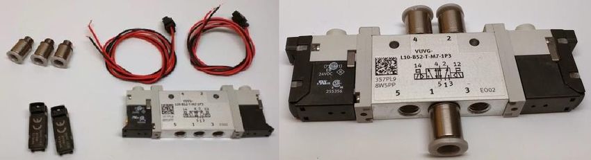
Working Pressure Side

 Figure 2 - Examples of working pressure side devices

The working pressure side of the pneumatics system has a bit more flexibility than the high-
pressure side. The following are some typical components you might find:
 • Solenoid Valve – an electromechanical component that switches airflow on and off to
 move pneumatic actuators. Valves used are typically either single solenoid valves which
 have 1 electrical connection and return to a specific state when power is removed (such
 as when the robot is disabled or powered off) or double solenoid valves which have two
 electrical connections and require an active signal to change state.
 • Pneumatic Actuator – air cylinders or rotary actuators that turn the compressed air into
 physical motion.
 • Manifold (optional) – A manifold is a block that allows the connection of multiple solenoid
 valves to a single input line. Many teams use these to reduce plumbing and ease
 mounting of solenoid valves.
 • One-way flow regulators (optional) – Generally placed downstream of a solenoid valve,
 a one-way flow regulator restricts the flow rate in one direction while allowing the full flow
 rate in the other direction. Restricting the flow into one side of an air cylinder will reduce
 the speed of movement in that direction without reducing the maximum force that the
 cylinder can provide.
 • Pressure regulators (optional) – Additional pressure regulators may be placed upstream
 or downstream of solenoid valves to further reduce the pressure for specific actuators in the
 system. This is generally done in order to reduce the maximum force applied by the
 cylinder, reduce the air consumption of the cylinder, or both.

 5
 Rev. Jan 2023

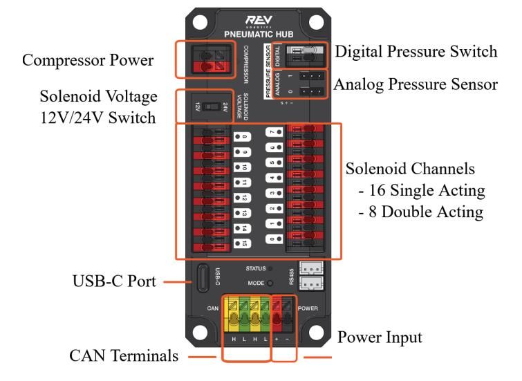
Pneumatics Controller
A pneumatics controller is an electronic component used to control the pneumatic system on the
robot. The controller operates the compressor to maintain air pressure in the system and actuates
the solenoid valves to control the movement of the cylinders. There are currently two legal
pneumatics controllers, the Pneumatic Hub (PH) from REV Robotics and the Pneumatics Control
Module (PCM) from Cross the Road Electronics. Both devices will control the compressor
automatically once robot software has set up a Solenoid object or VI and can control 12 or 24 volt
solenoids (though all solenoids on a robot must be the same voltage).

REV Robotics Pneumatic Hub

 Figure 3 - REV Robotics Pneumatics Hub

The REV Robotics Pneumatic Hub (PH) can support up to 16 single acting or 8 double acting
solenoids (or combinations adding to 16 total channels). The PH may be used with the digital
pressure switch or with a REV Analog Pressure Switch in place of, or in addition to, the digital
pressure switch.

 6
 Rev. Jan 2023
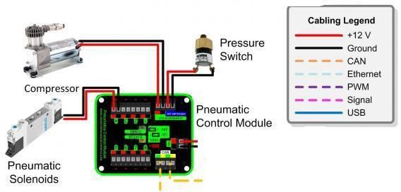
CTR Electronics Pneumatics Control Module

 Figure 4 - CTR Pneumatics Control Module and Wiring

The Cross the Road Electronics PCM can control 8 single solenoid valves or 4 double solenoid
valves. The PCM requires the use of a digital pressure switch.

 7
 Rev. Jan 2023
Plumbing a Basic Pneumatics Setup
This section details the assembly process for plumbing a basic pneumatics setup. For the
purpose of this setup documentation, all components are mounted to a bench top board.
Threaded Connections
 • Threaded connections should be made using PTFE thread sealing tape or another thread
 sealer. If using PTFE tape, the tape should be applied counterclockwise. Generally, the
 tape should be applied from approximately the second thread up to the thread closest to
 the device or pipe, with approximately ½ the tape width overlapped as you move up. For
 most FIRST Robotics Competition pneumatics components a single wrap biased towards
 the component side is sufficient.

 Figure 5 - PTFE tape example

 • Tighten all threaded connections using wrenches.
Quick-Disconnect Connections
 • When cutting tubes for quick connections, make sure the tube is long enough to not put
 any strain on the joint.
 • Ensure the tube is cut as square as possible. Specific tools are available for cutting
 pneumatic tube which help make this job easier, but it is completely doable with side
 cutters or similar tools with a little care.
 • To remove tubing from a quick-disconnect connector, first press and hold the plastic collar
 around the tubing (often a bright color like red, green or orange) in towards the body of the
 fitting, then pull the tubing away from the fitting.

 8
 Rev. Jan 2023
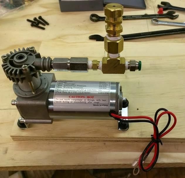
Compressor and Relief Valve

 Pressure Relief
 Push-to-
 Valve
 connect to ⅛”
 male thread
 ¼” female to ⅛” male
 thread adapter

 ⅛” Hex nipple

 ⅛” Union Tee

 Compressor

 Figure 6 - Compressor and relief valve plumbing

Steps
 1. Install a ⅛” hex nipple to the compressor output port.
 2. Connect a ⅛” union tee to the ⅛” hex nipple.
 3. Connect a ¼” female to ⅛” male thread adapter to the union tee
 4. Install the pressure relief valve to the ¼” adapter.
 5. Connect a push-to-connect to ⅛” male threaded fitting to the final slot on the union
 tee.
Compressor Tips
 • Because the compressor can produce a significant amount of vibration, we recommend
 that you use vibration isolation mounts that come preinstalled on the compressor. In order
 for these to isolate the vibration, they need to be mounted to a stiff piece of material.
 • The compressor can also get very hot and should not be in direct contact with anything
 else.
 o Some teams choose to have a fan blowing over the compressor to help cool it.
 o When running long practice sessions or many tightly spaced matches, it is
 possible for the heat of the compressor to heat the exiting air enough to cause
 adjacent tubing to heat and rupture. Modifying the layout shown above by using
 additional brass fittings (beyond the required relief valve) between the compressor
 and any tubing, such as a second tee for the pressure switch can provide an
 additional heatsink to help mitigate this.

 9
 Rev. Jan 2023
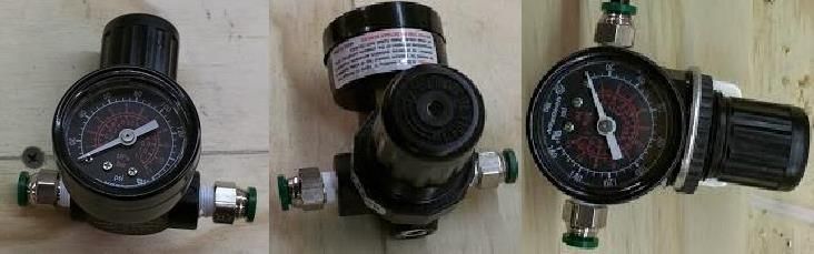
Pressure Switch, Gauge, and Vent Valve

 Pressure Gauge
 Pressure Switch

 Push-to-connect Vent valve
 to ⅛” male

 ⅛” Union ⅛” Hex ⅛” Union ⅛” Hex
 Tee Nipple Tee Nipple

 Figure 7- Pressure switch, gauge and vent valve plumbing

Steps:
 1. Attach a push-to-connect to ⅛” male threaded fitting to a slot on a ⅛” union tee.
 2. Install the pressure switch into the middle slot of the union tee.
 3. Connect a ⅛” hex nipple to the remaining port on union tee.
 4. Connect another union tee to the ⅛” hex nipple.
 5. Attach a pressure gauge to the middle port of the union tee.
 6. Connect another ⅛” hex nipple to remaining port on the second union tee.
 7. Attach the vent valve to the open threads on the ⅛” hex nipple.
Regulator and Gauge

 Figure 8 - Main regulator plumbing

Steps:
 1. Install one push-to-connect to ⅛” male threaded fitting into the outlet pressure port of
 the pressure regulator (generally designated by a larger plastic boss with an arrow
 pointing away from the regulator).
 2. Install another a push-to-connect to ⅛” male threaded fitting into the inlet port of the
 pressure regulator (this is the opposite port from the outlet where the other male

 10
 Rev. Jan 2023
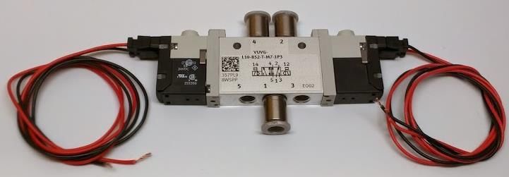
connector was just installed).
 3. Attach a pressure gauge to an open port on the pressure regulator.
 4. Plug the remaining port of the pressure regulator with a plug provided with the regulator
 or other ⅛” plug.
 5. The regulator should be mounted using the provided bracket and nut kit.
Actuation

 Figure 9 - Example pneumatic actuator

Steps:
 1. Attach push-to-connect fittings to both the inlet and outlet pressure port of the
 actuator. The thread size of the fitting will be determined by the port size on the cylinder.
 Depending on the location of the cylinder on the robot you may wish to use straight
 fittings instead of the elbow fittings pictured.
Electrical Valve

 Figure 10 - Example solenoid valve

Steps:
 1. Screw in all three push-to-connect fittings into ports 1, 2 and 4 of the Solenoid Valve.
 2. Connect both wires to the electrical sub bases.
Notes:
 • Many standalone valves used on robots have this general construction, the final product
 should look like the bottom image above but may not be exactly the same. If you are using
 a valve in conjunction with a manifold, the steps may be a bit different, make sure to follow
 the manufacturer’s instructions and plug unused ports on the manifold as needed.

 11
 Rev. Jan 2023
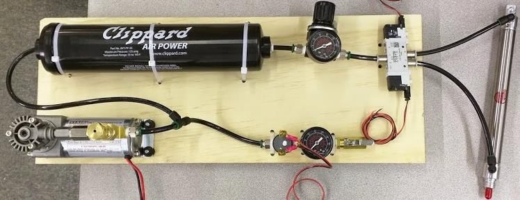
Air Tank

 Figure 11 - Example pneumatic air tank

Notes:
 • The air tank in the Kit of Parts uses two built-in push-to-connect fittings to make
 attachment easier.
 • NEVER use the air tank outside of operating conditions.
 • Install the air tank on the robot such that it is shielded from impact from other robots.
 • When fastening tank do not over tighten or cause pressure to the outside of the tank.
Plumbing

 Figure 12 - Example complete pneumatic system

Steps:
 1. Cut a piece of pneumatic tubing and connect it to the male push-to-connect fitting off
 the compressor + relief valve assembly.
 2. Connect a push-to-connect union tee to the other end of the pneumatic tubing.
 3. Cut another piece of pneumatic tubing and connect it between the union tee and the
 air tank.
 4. Cut a piece of pneumatic tubing to go between the open port on the air tank and the
 inlet pressure port on the regulator.
 5. Next cut a piece of pneumatic tubing to go between the outlet pressure port of the
 regulator and the inlet pressure port (1) of the electrical valve.
 6. Cut two more pieces of pneumatic tubing to go from the push-to-connect fittings on the
 electrical valve in ports 2 and 4 to the inlet and outlet ports on the actuator.

 12
 Rev. Jan 2023
Wiring and Software

Wiring Pneumatics
Wiring and software documentation is maintained online. To wire the pneumatic system please
refer to the “Wiring Pneumatics” document.

Software Setup
To setup a CTR Electronics PCM, see the Bring Up the CAN page to learn about Phoenix Tuner
and how to use it to set up your PCM .To setup a REV Pneumatic Hub, see the REV Hardware
Client.
To add pneumatics to your robot code, refer to the “Operating pneumatic cylinders” document.

Operational tests

Confirm Operation and Pressure Switch Functionality
After plumbing, wiring, and configuring the software on the system, the next step is to validate
that the compressor turns on and off appropriately under the control of the pressure switch.
During this procedure, make sure to monitor the pressure gauge for the high-pressure
side of the system and immediately disable or power off the system if pressure begins to
exceed 125 psi.
 1. Ensure the pneumatic plug valve is closed to allow the system to pressurize.
 2. Power on the robot and connect the driver station computer to the robot (wirelessly or
 using a wired USB or Ethernet connection).
 3. Using the Driver Station software, enable the robot. The compressor should begin running
 automatically.
 4. Observe the pressure gauge for the high-pressure side of the system. The compressor
 should shut off when the pressure reaches ~110-120 psi. If the pressure exceeds 125
 psi disable or power off the robot immediately. If the system stops building pressure
 prior to shutting off (at a pressure lower than 110 psi), the system has a significant leak;
 see the steps in the section “Leak Test” below for assistance in locating and resolving the
 leak prior to proceeding.

 13
 Rev. Jan 2023
Validation of Relief Valve Operation

 Figure 13 - Pressure relief valve

The next critical step is to ensure correct operation of the pressure relief valve. If using an
adjustable relief valve this step also includes calibrating the relief valve to relieve at the correct
pressure. Two separate sets of instructions are provided below, one set for validating the
operation of a factory calibrated relief valve and one set for configuring and validating an
adjustable relief valve.
Adjustable Relief Valve
 1. Loosen the locknut on the relief valve by screwing it away from the cap.
 2. Enable the robot and allow the pneumatic pressure to build until the compressor shuts
 off.
 3. Jumper across the terminals of the Pressure Switch so that the compressor begins
 running again (using alligator clips or a metal tool).
 4. When pressure gets to 125 psi, remove the jumper. The compressor should shut off
 immediately, if it does not, disable or power off the robot.
 5. Rotate the relief valve cap until air begins to escape and the pressure remains in the 120-
 125 psi range. If the pressure drops too low, rotate the cap back a bit and re-pressurize
 the system by applying the jumper to the Pressure Switch.
 6. Finger tighten the locknut up against the cap.
 7. Dump air from system by briefly actuating the plug valve (dropping to 90-100 psi is
 sufficient) then refill by again applying the jumper to the Pressure Switch.
 8. Monitor the pressure gauge closely, the relief valve should begin relieving around 120-
 125 psi and the system pressure should not significantly exceed 125 psi. If the pressure
 reaches 130 psi, disable the compressor immediately by removing the jumper, disabling
 the robot or powering off the robot. If this occurs, or if the pressure stabilizes too low,
 return to step 4 to adjust the calibration.
 9. If the system stabilizes somewhere between 120-125 psi further tighten down the locknut
 using a wrench.
 10. Finally, dump air from the system by briefly actuating the plug valve until the compressor
 enables. Allow the system to fill until the compressor shuts off, verifying that the relief
 valve does not begin to relieve pressure before the compressor shuts off.

 14
 Rev. Jan 2023
Factory Set Relief Valve
 1. Enable the robot and allow the pneumatic pressure to build until the compressor shuts
 off.
 2. Jumper across the terminals of the Pressure Switch so that the compressor begins
 running again (using alligator clips or a metal tool).
 3. Monitor the system pressure. The relief valve should operate at approximately 125 psi. If
 the system reaches 130 psi, shut off the compressor by removing the jumper, disabling
 the robot, or shutting off the robot. Warning: Many of these valves are fairly loud
 when they trigger.
 4. If the valve operates properly, the procedure is complete. If the valve does not operate, it
 is likely that either the valve or the gauge are not calibrated or operating properly, swap
 one or the other with a spare and repeat the procedure until proper operation can be
 verified.

Leak Test
After verifying that the system can be controlled safely you likely want to check the system for
leaks.
 1. Enable the robot and allow the pressure to fill until the compressor turns off (~110-120
 psi). If a large leak is preventing the pressure from reaching the shutoff point you may
 want to charge to the highest stable pressure and then disable the robot to better hear
 where the leak is coming from.
 2. Verify that the pressure appears to remain visibly stable and no hissing sound can be
 heard. If the pressure is visibly dropping or a hissing sound is a heard, a significant leak is
 present.
 a. Large leaks can often be localized to a small area using the hissing sound and can
 usually be felt by hand. Sometimes wetting a finger can help provide increased
 sensitivity to the flowing air. Check each connection point to locate the leak.
 b. Typical causes of large leaks are:
 i. Relieving regulator installed backwards
 ii. Incorrectly plumbed valve or manifold
 iii. Missing plug on manifold or regulator.
 iv. Tube not fully inserted in quick connect or cut significantly off square
 v. Threaded fitting not tight
 3. Leave the robot pressurized for a bit and verify that the pressure does not drop
 significantly. While a robot can be made to hold pressure for a day or more with minimal
 pressure drop, generally a drop of less than 10 psi over ~30 minutes is a good target. This
 timeframe allows for a robot system charged in the queue to maintain most or all of its
 stored air by the time the match starts.
 a. Small leaks may be more difficult to identify. You may try wetting your finger and
 moving it around connection points but a more through technique may be required.
 b. A common technique for locating smaller leaks is to use a bubbling solution. While
 solutions intended specifically for leak detection are available, children’s bubble

 15
 Rev. Jan 2023
solution or a ~4:1 mix of water to dish soap also work just fine for robots.
 i. Make sure to cover any electronics, gearboxes, or other sensitive
 components you don’t want to get wet.
 ii. With the system pressurized, begin applying a small amount of solution to
 each connection point. Solution may be applied using a finger, paintbrush,
 sponge, or spray bottle depending on your preference and the accessibility
 of your pneumatic components.
 iii. Look for bubbles to form indicating the source of a leak.
 c. Common sources of smaller leaks include:
 i. Threaded connections with improper or no thread sealing
 ii. Threaded connections that are slightly loose
 iii. Push-to-connect tubing connections with a tube cut slightly off square or
 placed under tension
 4. Actuate any pneumatic cylinders into their alternate state, check the pressure reading
 (allow the compressor to refill the tanks if it kicks on) and leave the robot for another 30
 minutes. This tests the seal on the remaining connections from the valves to the alternate
 side of the air cylinders.

Tuning actuator speed/force
After testing your pneumatics, you may find that some of your air cylinders move more quickly
than you would like them to. Depending on what acts as a stop, violent actuation of a mechanism
may result in damage to the mechanism, air cylinder, or other robot components. There are two
main ways you can reduce the speed of a pneumatic actuator:
 • Reduce pressure using a regulator – This reduces the force produced by the regulator
 which reduces the force available for acceleration of the load. As an added benefit,
 reducing pressure also reduces the air consumption of the actuation. There are a couple
 ways you can reduce the pressure of an actuation:
 o Reduce system pressure – If all cylinders on your robot can actuate properly in
 both directions with less pressure, you may choose to reduce the pressure of the
 main regulator below 60psi. The downside of this approach is it is a single control
 for both directions of all pneumatics on your robot.
 o Additional regulator before solenoid – If both directions of a single actuator need
 reduced pressure you may place an additional regulator upstream of the inlet of
 the solenoid valve. This will allow you to precisely dial the applied pressure to the
 needs of that mechanism without impacting any other pneumatics used on the
 robot.
 o Additional regulator after solenoid – Sometimes only a single direction of an
 actuator needs pressure control such as when a mechanism is assisted by gravity
 in one direction and fighting it in the other. In this case you can place a regulator
 downstream of the solenoid on only the output that needs it. This allows you to
 apply higher pressure when the actuator moves one direction and lower pressure
 when it moves the other direction. Note when performing air usage calculations

 16
 Rev. Jan 2023
that the tubing between the valve and regulator will still contain higher pressure air
 which will be lost when the valve is switched, depending on the length of the
 tubing, this may or may not be significant.
• Control flow rate using a valve – A flow control valve (a.k.a. needle valve) can reduce
 the speed an actuator moves while maintaining the maximum force that the actuator can
 apply. There are two primary types of flow control valves useful for robots:
 o One way flow control valves – These valves restrict the flow passing through them
 in one direction and allow full unrestricted flow to pass the other way. Often an
 arrow on the body marks the direction of restricted flow.
 o Bi-directional flow control valves – These valves restrict the flow passing in either
 direction.
 Flow control valves are generally placed downstream of the solenoid valve. There are a
 couple ways that flow control valves can be configured depending on the air cylinder
 configuration:
 o Single acting air cylinder (spring return)
 o Meter-in – Place a one-way flow control valve restricting flow into the air
 cylinder, slowing the movement of the cylinder against the spring. The
 spring will act as a variable load helping to resist any jerk in the motion of
 the cylinder. The retract action of the cylinder powered by the spring will not
 be restricted
 o Bidirectional – Use a bi-directional flow control to control air into and out of
 the cylinder. This will restrict the rate of movement in both directions.
 o Double acting cylinder
 o Meter-in one direction – Place a one-way flow control on one input of the
 cylinder restricting air into the cylinder. This will restrict the speed of the
 cylinder moving away from that port, but may result in jerky movement.
 Meter-out is generally a more recommended configuration.
 o Meter-in both directions – Place one-way flow controls on both inputs of the
 cylinder restricting air into the cylinder. This will restrict the speed of the
 cylinder moving away from that port, but may result in jerky movement.
 Meter-out is generally a more recommended configuration.
 o Meter-out one direction – Place a one-way flow control on one input of the
 cylinder restricting air leaving the cylinder. This will restrict the speed of the
 cylinder moving towards that port. The air attempting to leave the cylinder
 will be restricted and become compressed, acting like a spring slowing the
 movement of the cylinder.
 o Meter-out both directions – Place one-way flow controls on both inputs of
 the cylinder restricting air leaving the cylinder. This will restrict the speed of
 the cylinder in both directions. The air attempting to leave the cylinder will
 be restricted and become compressed, acting like a spring slowing the
 movement of the cylinder.

 17
 Rev. Jan 2023
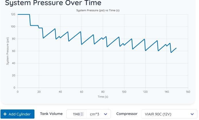
Designing with Pneumatics

Identifying Required Stroke
When designing for pneumatics, the first step is typically to identify the required stroke length.
This is typically done by designing the linear mechanism or linkage and measuring the desired
travel. Note that you will need to make sure you have room for the cylinder, the fixed cylinder
body will have a length equal to the travel distance plus some additional length. For single acting
spring return cylinders this additional length generally scales with both stroke and bore size, for
double acting cylinders this additional length typically does not depend on stroke. As a rough
ballpark, this “dead length” for double mount, double acting cylinders often ranges from about 2.5
in. for a 5/16 in. bore cylinder to about 7 in. for a 2 in. bore cylinder.

Calculating Bore Size
Bore size of a pneumatic cylinder should be selected based on the force required. The force
applied in the extend direction can be calculated simply using the bore size and the pressure
(typically 60 psi). With pressure in pounds-per-square-inch, all that is required is to calculate the
area of the bore in inches and multiply in order to get force in pounds.
 ( ) = ( ) ∗ ∗ ( )
In the retract direction, the cylinder rod will reduce the effective bore, so you will need to subtract
the area of the rod from the area of the bore when performing the calculation. This means that the
cylinder will apply less force when retracting than when extending.
 ( ) = ( − ) ( ) ∗ ∗ ( )

Evaluating Air Usage
The last set of calculations to consider when using pneumatics is related to the total air usage
throughout the match. Teams typically pre-charge the air reservoirs on the robot prior to the
match. As you start actuating the air cylinders on the robot, the pressure in the reservoirs will
decrease until around 90psi when the compressor kicks on. If the compressor fill rate is faster
than the rate of consumption, the pressure will then increase until it reaches 120psi again, if not
the pressure will continue to decrease. The critical point is when the pressure begins to drop
below the pressure being used by the cylinders. At that point the cylinder actuation may slow
down or stop altogether.
While it is easy to calculate the air used by a single cylinder actuation, the inflow from the
compressor makes it a bit complicated to calculate the reservoir pressure throughout the match
by hand. Using a calculator, such as the one found on ReCalc, is often the easiest way to
visualize the system pressure at any point in a theoretical match. These calculators take the
compressor type, and information about the size, pressure, and frequency of cylinder actuation as
inputs and output a graph of reservoir pressure over time.

 18
 Rev. Jan 2023
Figure 14 – Example 1: ReCalc Output

In this example graph above, the air utilization is greater than what can be refilled by the
compressor until the pressure reaches approximately 40 psi (the compressor flow rate increases
as pressure decreases). If this is not enough to actuate one or more of your cylinders, you will
need to reduce air usage by decreasing pressure, volume (by reducing stroke or bore) or use
frequency of the air cylinders (example 2 below), or increase storage such that the pressure
remains above 60 psi during the match (example 3 below)

 Figure 15 - Example 2: Increased Volume

 Figure 16 - Example 3: Decreased Usage

 19
 Rev. Jan 2023
Getting Pneumatics Parts
Many pneumatics components are available in the Kit of Parts (including FIRST Choice) thanks to
the generosity of our suppliers.
Additional components are available from these suppliers and/or their distributors, common
industrial parts suppliers, common FIRST Robotics Competition vendors, and more.

 20
 Rev. Jan 2023
You can also read