FUZE MAX PROFILE user manual - Elation Professional
←
→
Page content transcription
If your browser does not render page correctly, please read the page content below

FUZE MAX PROFILE
user manual
©2022 ELATION PROFESSIONAL all rights reserved. Information, specifications, diagrams, images, and
instructions herein are subject to change without notice. ELATION PROFESSIONAL logo and identifying
product names and numbers herein are trademarks of ELATION PROFESSIONAL. Copyright protection
claimed includes all forms and matters of copyrightable materials and information now allowed by
statutory or judicial law or hereinafter granted. Product names used in this document may be trademarks
or registered trademarks of their respective companies and are hereby acknowledged. All non-ELATION
brands and product names are trademarks or registered trademarks of their respective companies.

ELATION PROFESSIONAL and all affiliated companies hereby disclaim any and all liabilities for property,
equipment, building, and electrical damages, injuries to any persons, and direct or indirect economic
loss associated with the use or reliance of any information contained within this document, and/or as a
result of the improper, unsafe, insufficient and negligent assembly, installation, rigging, and operation
of this product.

Elation Professional USA | 6122 S. Eastern Ave. | Los Angeles, CA. 90040
323-582-3322 | 323-832-9142 fax | www.elationlighting.com | info@elationlighting.com

Elation Professional B.V. | Junostraat 2 | 6468 EW Kerkrade, The Netherlands
+31 45 546 85 66 | +31 45 546 85 96 fax | www.elationlighting.eu | info@elationlighting.eu

Elation Professional Mexico | AV Santa Ana 30 | Parque Industrial Lerma, Lerma, Mexico 52000

+52 (728) 282-7070

DOCUMENT VERSION
               Due to additional product features and/or enhancements, an updated version of this
               document may be available online. Please scan the QR Code with your mobile device or
               visit www.elationlighting.com for the latest revision/update of this manual, before
               installation and/or programming.

                     Document
      Date                          SoftwareVersion ≥   DMX Channel Modes               Notes
                      Version
  02/08/2022            1.0                1.0.0            40/61/38/57             Initial Release
  05/17/2022            1.1                N/C               No Change          Updated Specifications

                                                   2
CONTENTS

   General Information                 4
   Warranty Returns (USA Only)         5
   Safety Guidelines                   6
   Maintenance Guidelines              8
   Overview                            9
   Colors Temperature Table            10
   Virtual Gel Swatch Book Table       10
   Gobos & Gobo Wheels                 11
   Gobo Installation
      Rotating Gobo Wheel 1            12
      Fixed Gobo Wheel                 13
   Gobo Dimensions                     14
   Fan Modes and Low Noise Operation   15
   Snoot Installation                  16
   Installation Guidelines             17
   System Menu                         21
   Dimmer Mode                         24
   DMX Channel Functions and Values    25
   RDM Codes                           33
   Error Codes                         34
   Specifications                      35
   Optional Accessories                38

                                 3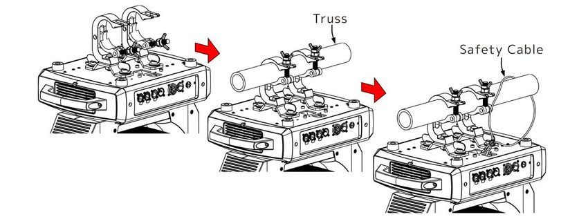
G E N E R A L I N F O R M AT I O N
INTRODUCTION
Please read and understand the instructions in this manual carefully and thoroughly before
attempting to operate this device. These instructions contain important safety and use
information. For professional use only.
IP65 RATED
An IP rated lighting fixture is one, which is commonly installed in outdoor environments and
has been designed with an enclosure that effectively protects the ingress (entry) of external
foreign objects such as dust and water. The International Protection (IP) rating system is
commonly expressed as "IP" (Ingress Protection) followed by two numbers (i.e. IP65) where the
numbers define the degree of protection. The first digit (Foreign Bodies Protection) indicates
the extent of protection against particles entering the fixture and the second digit (Water
Protection) indicates the extent of protection against water entering the fixture. An IP65
rated lighting fixture is one, which has been designed and tested to protect against the ingress
of dust (6) and low-pressure water jets from any direction (5).

COOLING
After usage, the lamp may be switched off, but the fixture should remain connected to power
in order to allow the fan time to cool down the fixture.
UNPACKING
Every device has been thoroughly tested and has been shipped in perfect operating condition.
Carefully check the shipping carton for damage that may have occurred during shipping. If
the carton is damaged, carefully inspect the device for damage, and be sure all accessories
necessary to install and operate the device have arrived intact. In the event damage has been
found or parts are missing, please contact our customer support team for further instructions.
Please do not return this device to your dealer without first contacting customer support.
Please do not discard the shipping carton in the trash. Please recycle whenever possible.
BOX CONTENTS
Omega Brackets (x2)
IP65 Rated Twist-Lock Power Cable
CUSTOMER SUPPORT
Contact ELATION Service for any product related service and support needs.
Also visit forums.elationlighting.com with questions, comments or suggestions.
ELATION SERVICE USA - Monday - Friday 8:00am to 4:30pm PST
323-582-3322 | Fax 323-832-9142 | support@elationlighting.com
ELATION SERVICE EUROPE - Monday - Friday 08:30 to 17:00 CET
+31 45 546 85 63 | Fax +31 45 546 85 96 | support@elationlighting.eu
REPLACEMENT PARTS please visit parts.elationlighting.com

                                               4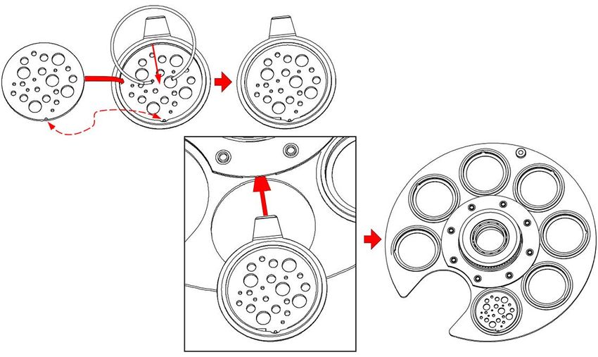
WA R R A N T Y R E T U R N S ( U S A O N LY )
To obtain warranty service, a Return Materials Authorization (RMA) number must first
be obtained from ELATION. It is the Customer’s responsibility to provide product proof of
purchase and serial number by acceptable evidence such as an invoice copy or an approved
ELATION Extended Warranty Certificate (“EWC”) and any relevant maintenance records at the
time warranty service is sought. Failure to provide acceptable evidence of product proof of
purchase or EWC and any relevant maintenance records may be cause for denial of warranty
service.

Products returned for warranty service must be sent without any accessories (i.e., power, data,
and safety cables, brackets, clamps, rigging hardware, frost filters, gel frames, barn doors,
lens, hoses, nozzles, rack mounting hardware, etc.), must be boxed using the original and/or
suitable packaging materials (double-box and foam) that provides ample product protection
for ground and/or air freight transit, and must be shipped freight pre-paid and insured to
ELATION in Los Angeles, CA or an ELATION Authorized Service Center. The RMA number must
be clearly written on the outside of the return box, and a brief description of the problem and
the RMA number must be documented and included in the box.

Products returned for warranty service without an RMA number clearly marked on the outside
of the package will be refused and returned to the shipper at the Customer’s expense. Products
returned for warranty service, which are received damaged due to inadequate and/or improper
packaging and/or due to damage caused by shipping carrier, may incur additional repair charges
before warranty service begins and/or may void this warranty. If any product accessories
(included and/or optional) are shipped with the product, ELATION and/or the ELATION
Authorized Service Center shall have no liability what so ever for the loss and/or damage to
any such accessories, nor the safe return thereof. If the requested warranty repairs or service
(including parts replacement) are within the terms of this warranty, ELATION will pay return
ground transportation shipping charges to a single designated point within the United States.

                                              5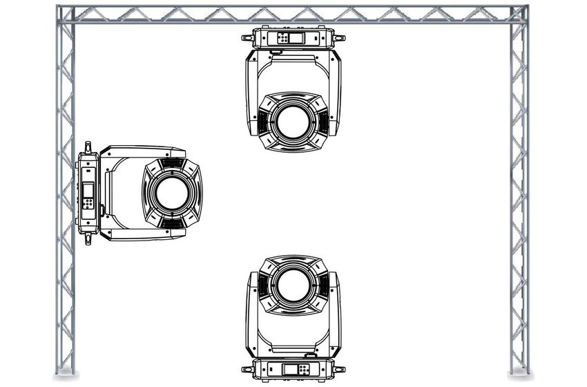
SAFETY GUIDELINES
This fixture is a sophisticated piece of electronic equipment. To guarantee a smooth operation,
it is important to follow all instructions and guidelines in this manual. Elation Professional is
not responsible for injury and/or damages resulting from the misuse of this fixture due to the
disregard of the information printed in this manual. Only qualified and/or certified personnel
should perform installation of this fixture and only the original rigging parts (omega brackets)
included with this fixture should be used for installation. Any modifications to the fixture and/
or the included mounting hardware will void the original manufactures warranty and increase
the risk of damage and/or personal injury.

              PROTECTION CLASS 1 - FIXTURE MUST BE PROPERLY GROUNDED.

              THERE ARE NO USER SERVICEABLE PARTS INSIDE THIS UNIT.
              DO NOT ATTEMPT ANY REPAIRS YOURSELF; DOING SO WILL VOID YOUR
              MANUFACTURER’S WARRANTY. DAMAGES RESULTING FROM MODIFICATIONS
              TO THIS FIXTURE AND/OR THE DISREGARD OF SAFETY INSTRUCTIONS AND
              GUIDELINES IN THIS MANUAL VOID THE MANUFACTURE’S WARRANTY AND
              ARE NOT SUBJECT TO ANY WARRANTY CLAIMS AND/OR REPAIRS.

              DO NOT PLUG FIXTURE INTO A DIMMER PACK!
              NEVER OPEN THIS FIXTURE WHILE IN USE!
              UNPLUG POWER BEFORE SERVICING FIXTURE!
              NEVER TOUCH FIXTURE DURING OPERATION, AS IT MAY BE HOT!
              KEEP FLAMMABLE MATERIALS AWAY FROM FIXTURE!

              NEVER LOOK DIRECTLY INTO THE LIGHT SOURCE!
              RETINA INJURY RISK - MAY INDUCE BLINDNESS!
              SENSITIVE PERSONS MAY SUFFER AN EPILEPTIC SHOCK!

              INDOOR / DRY LOCATIONS USE ONLY!
              DO NOT EXPOSE FIXTURE TO RAIN AND MOISTURE!

              MINIMUM DISTANCE TO OBJECTS/SURFACES
              MUST BE 65.6 FEET (20 METERS)
              MAXIMUM TEMP OF EXTERNAL SURFACE 185° F (85°C)
              MINIMUM DISTANCE OF INFLAMMABLE MATERIALS
              FROM THE SURFACE 1.6 FEET (0.5 METER)

                                               6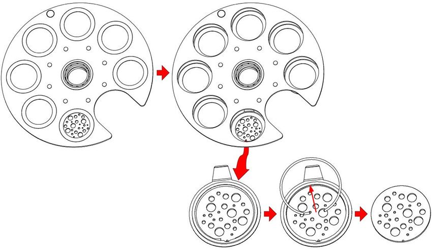
SAFETY GUIDELINES

                                RISK GROUP 3 - RISK OF EXPOSURE TO ULTRAVIOLET UV
                                RADIATION! FIXTURE EMITS HIGH INTENSITY WAVELENGTH
                                OF ULTRAVIOLET UV LIGHT FROM THE UV COLOR FILTER.
                                WEAR PROPER EYE AND SKIN PROTECTION. AVOID
                                PROLONGED PERIODS OF EXPOSURE TO UV COLOR FILTER.
                                AVOID WEARING WHITE COLOR CLOTHING AND/OR USING UV
                                PAINTS ON SKIN. AVOID DIRECT EYE AND/OR SKIN EXPOSURE
                                AT DISTANCES LESS THAN 65.6 feet (20m). DO NOT OPERATE
                                FIXTURE WITH DAMAGED/MISSING EXTERNAL COVERS. DO
                                NOT LOOK DIRECTLY INTO THE UV LIGHT AND/OR VIEW UV
                                LIGHT DIRECTLY WITH OPTICAL INSTRUMENTS THAT MAY
                                CONCENTRATE THE LIGHT/RADIATION OUTPUT. INDIVIDUALS
                                SUFFERING FROM A RANGE OF EYE CONDITIONS, SUNLIGHT
EXPOSURE DISORDERS, OR INDIVIDUALS USING PHOTOSENSITIVE MEDICATION, MAY RECEIVE
DISCOMFORT IF EXPOSED TO THE ULTRAVIOLET UV LIGHT EMITTED FROM THE UV LED.
DO NOT TOUCH the fixture housing during operation. Turn OFF the power and allow approximately
15 minutes for the fixture to cool down before serving.
DO NOT shake fixture, avoid brute force when installing and/or operating fixture.
DO NOT operate fixture if the power cord is frayed, crimped, damaged and/or if any of the power
cord connectors are damaged and do not insert into the fixture securely with ease. NEVER force
a power cord connector into the fixture. If the power cord or any of its connectors are damaged,
replace it immediately with a new one of similar power rating.
DO NOT block any air ventilation slots.
All fan and air inlets must remain clean and never blocked.
Allow approx. 6” (15cm) between fixture and other devices or a wall for proper cooling.
Always disconnect fixture from main power source before performing any type of service and/or
cleaning procedure. Only handle the power cord by the plug end, never pull out the plug by tugging
the wire portion of the cord.
During the initial operation of this fixture, a light smoke or smell may emit from the interior of the
fixture. This is a normal process and is caused by excess paint in the interior of the casing burning
off from the heat associated with the lamp and will decrease gradually over time.
Consistent operational breaks will ensure fixture will function properly for many years.
ONLY use the original packaging and materials to transport the fixture in for service.
                                                  7
MAINTENANCE GUIDELINES
            DISCONNECT POWER BEFORE PERFORMING ANY MAINTENANCE!

CLEANING
Frequent cleaning is recommended to insure proper function, optimized light output, and an
extended life. The frequency of cleaning depends on the environment in which the fixture
operates: damp, smoky or particularly dirty environments can cause greater accumulation
of dirt on the fixture’s optics. Clean the external lens surface at least every 20 days with
a soft cloth to avoid dirt/debris accumulation.
NEVER use alcohol, solvents, or ammonia-based cleaners.

MAINTENANCE
Regular inspections are recommended to insure proper function and extended life.
There are no user serviceable parts inside this fixture, please refer all other service issues
to an authorized Elation service technician. Should you need any spare parts, please order
genuine parts from an authorized Elation dealer.
Please refer to the following points during routine inspections:
A detailed electric check by an approved electrical engineer every three months, to make
sure the circuit contacts are in good condition and prevent overheating.
Be sure all screws and fasteners are securely tightened at all times. Lose screws may fall
out during normal operation resulting in damage or injury as larger parts could fall.
Check for any deformations on the housing, color lenses, rigging hardware and rigging
points (ceiling, suspension, trussing). Deformations in the housing could allow for dust to
enter into the fixture. Damaged rigging points or unsecured rigging could cause the fixture
to fall and seriously injure a person(s).
Electric power supply cables must not show any damage, material fatigue or sediments.
NEVER remove the ground prong from the power cable.

FIXTURE DISASSEMBLY
The following points should be observed after performing any maintenance procedure that
requires disassembly of the unit:
• After the unit has been reassembled, open the valve, and allow the light to run for
   approximately 2 hours in order to dry out any moisture that has been trapped inside the
   fixture. The process should continue until indicated humidity drops below 15% for the
   head and 30% for the base.
• Once this has been achieved, the light can be switched off, but the unit should remain
   connected to power so that the cooling fan can cool down the unit. Please note that
   allowing cool down time should ALWAYS be done after lamp operation.
• Some units may require partial disassembly in order to gain access to the valve. Please
   contact Elation service for information regarding the location and access procedure for
   the valve on your specific unit model.
                                              8
OVERVIEW

                        LENS

                                   Fuse: T15A / 250V                     RJ45 In/Out
  Service Port
                                 UP Button     Power Connector Locking 5-Pin DMX
LCD Control Display                                In/Out            In/Out
        Battery Level
                                 DOWN Button
                 MENU Button
                               ENTER Button

                                         9
C O LO R S
Colors Color Temperature Green Shift
Cyan
Full Minus Green to
Magenta Neutral
Yellow
Red
2700K – 8500K Neutral White
Green
Blue
Mint Neutral to Full Plus Green
Amber
VIRTUAL GEL SWATCH BOOK COLORS
Filter Filter Filter
Value Number Name Value Number Name Value Number Name
1 7 Pale Yellow 21 157 Pink 41 68 Sky Blue
2 103 Straw 22 36 Medium Pink 42 143 Pale Navy Blue
3 151 Gold Tint 23 111 Dark Pink 43 131 Marine Blue
4 100 Spring Yellow 24 128 Bright Pink 44 115 Peacock Blue
5 10 Medium Yellow 25 148 Bright Rose 45 172 Lagoon Blue
6 101 Yellow 26 332 Special Rose Pink 46 116 Medium Blue Green
7 104 Deep Amber 27 793 Vanity Fair 47 90 Dark Yellow Green
8 15 Deep Straw 28 113 Magenta 48 139 Primary Green
9 179 Loving Amber 29 46 Dark Magenta 49 122 Fern Green
10 21 Gold Amber 30 48 Rose Purple 50 89 Moss Green
11 105 Orange 31 126 Mauve 51 124 Dark Green
12 158 Deep Orange 32 49 Medium Purple 52 88 Lime Green
13 22 Dark Amber 33 58 Lavender 53 138 Pale Green
14 778 Millennium Gold 34 199 Palace Blue 54 203 Quarter CT Blue
15 135 Deep Golden Amber 35 119 Dark Blue 55 202 Half CT Blue
16 24 Scarlet 36 132 Medium Blue 56 201 FULL CT Blue
17 106 Primary Red 37 120 Deep Blue 57 200 Double CT Blue
18 26 Bright Red 38 165 Daylight Blue 58 206 Quarter CT Orange
19 27 Medium Red 39 161 Slate Blue 59 205 Half CT Orange
20 19 Fire 40 118 Light Blue 60 204 FULL CT Orange
10GOBOS & GOBO WHEELS
11G O B O I N S TA L L AT I O N - R O TAT I N G G O B O W H E E L 1
Locate the Rotating
GOBO being replaced.
Carefully press the
GOBO Holder down,
then pull it out and
away until it fully
clears the Fixed GOBO
Wheel.
Locate the tab of the Retention
Spring, and with a precision pick
(or similar tool), carefully press the
Retaining Spring inward to relieve the
tension. Remove the retaining spring
and carefully separate the GOBO from
the GOBO Holder.
CAUTION: TAKE CARE NOT TO SCRATCH GOBO OR GOBO HOLDER
To ensure proper Gobo orientation on the Rotating Gobo Wheel, align the Alignment Indices
before installing the Retention Spring. These indices are the notch in the Gobo Holder, the dot
on the top and bottom of the Gobo Holder Retention Tab, and the Gobo itself.
Alignment Indices
Note that the Gobo
Holder straddles
the Rotating Gobo
Wheel in the Gobo
Holder Slot, with
the gearing on
one side, and the
Retention Tab is on
the other.
Rotate the Gear of the
Rotating Gobo Wheel until
the Gear Alignment Dot on
the bottom of the Rotating
Gobo Wheel is lined up with
the empty Gobo Holder Slot.
Install the Gobo Holder Tab
into the Gobo Holder Tab
Receptacle and press until
the Gobo Holder gently
springs into the empty Gobo
Holder Slot.
12G O B O I N S TA L L AT I O N - F I X E D G O B O W H E E L 2
Locate the Fixed
Gobo being replaced.
Carefully press the
Gobo Holder down,
then pull it out and
away until it fully
clears the GOBO
Wheel.
Locate the tab of the Retention
Spring, and with a precision pick
(or similar tool), carefully press the
Retention Spring inward to relieve the
tension. Remove the retaining spring
and carefully separate the GOBO from
the GOBO Holder.
CAUTION: TAKE CARE NOT TO SCRATCH GOBO OR GOBO HOLDER
To ensure proper Gobo orientation on the Fixed Gobo Wheel, align the orientation indices
before installing the Retention Spring. These indices are the notch in the Gobo Holder and the
dot on the Gobo itself.
Note that the Gobo Holder
does not straddle the
Fixed Gobo Wheel in the
Gobo Holder Slot.The the
Retention Tab is on same
side as the Gobo Holder.
Install the Gobo Holder Tab
into the Gobo Holder Tab
Receptacle and press until
the Gobo Holder gently
springs into the empty
Gobo Holder Slot.
13GOBO DIMENSIONS
Gobos for Rotating Gobo Wheel and Static Gobo Wheel
Please be aware of the intended position and correct sizing requirements of custom gobos.
* * * IMPORTANT NOTICE REGARDING CUSTOM GOBOS * * *
Due to the high temperature optical system, special glass material is required for custom gobos.
Due to varying manufacturing processes and tolerances, it is highly recommended to provide a
gobo sample and holder from the fixture to the custom gobo vendor for accurate sizing. Extended
testing of custom gobo designs is highly recommended prior to use. Contact ELATION SERVICE for
further information.
ELATION SERVICE USA -Monday -Friday 8:00am to 4:30pm PST
323-582-3322 | Fax 323-832-9142 | support@elationlighting.com
ELATION SERVICE EUROPE -Monday -Friday 08:30 to 17:00 CET
+31 45 546 85 63 | Fax +31 45 54685 96 | support@elationlighting.eu
14FA N M O D E S A N D LO W N O I S E O P E R AT I O N
This fixtureis a high-performance fixture suited for many applications. For noise critical
environments like Theater, Opera or Orchestra Halls, it offers various operation modes to remove
any distraction for the audience and performers. Modes can be changed remotely via the DMX
control channel, allowing the fixture to offer high output or whisper silent operation at a moment’s
notice. All modes smoothly transition over a brief period, preventing unwanted attraction to the
fixture.
Mode dbA at 1m LED off dbA at 1m Dimmer 100%
Ambient Noise Level 31 dbA
Fan Control - Auto (Default) 39 47
Fan Control - Low 37 42
Fan Control - High 40 55
Low Noise - Mute 31 31
Low Noise - Studio 34 37
Fan Modes
Auto – The default AUTO mode ensures optimal performance of the fixture. Fans only run at the speeds
needed to keep the LED engine within a safe temperature range. They will turn off if possible, for
example when the fixture is dimmed to a low intensity. Fans sense the ambient and fixture temperature,
and will at all times try to keep noise levels at a minimum. The fixture output will only reduce when the
LED engine cannot be cooled down to its safe operating range due to high ambient temperature. Auto
is the recommend mode for daily operation of the Fuze Max Spot.
Low – In this mode the fixture reduces fan speeds throughout for a lower noise profile of the fixture.
This mode should be sufficient for most uses where lower noise is required. The fixture output is reduced
to about 80%.
High – This mode is only required in very high ambient temperatures when automatic fan speed
adjustments are not desired. High Fan Speed will cool the fixture most efficiently. This mode will increase
wear on the fans and should only be utilized in exceptional circumstances. Fans will always run, even if
the fixture is dimmed. Fixture output is kept at 100% unless the LED engine temperature is too high, at
which point the fixture will reduce power carefully to ensure safe operation.
Low Noise Modes
For very critical situations, the fixture offers two additional low noise modes for silent operation. The
fixture output will be reduced, but as the fixture has such an extremely high luminous flux, it still offers
outstanding performance. In low noise modes, all parameters of the fixture operate quieter and with
reduced speeds.
Studio – This mode reduces the fixture output to approximately 50%. Almost all fans inside the fixture
are turned off, and only run when absolutely necessary to keep the fixture at 50% LED power.
Mute – Running the fixture in MUTE mode reduces the fixture to about 25% output, and all fans are off.
The fixture is totally silent.
15S N O O T I N S TA L L AT I O N
1. Place fixture on the stable flat surface and let cool for 15mins.
2. Place snoot onto front lens so snoot screw holes match screw holes on lens.
3. Carefully, using a hand screwdriver, secure 4 screws (included).
4. Check Snoot to confirm it is seated properly, and all 4 screws are secure.
DO NOT OVER TIGHTEN SCREWS! DO NOT USE A POWER SCREWDRIVER!
16INSTALLATION GUIDELINES
FLAMMABLE MATERIAL WARNING
Keep fixture minimum 5.0 feet (1.5m) away from flammable materials and/or pyrotechnics.
ELECTRICAL CONNECTIONS
A qualified electrician should be used for all electrical connections and/or installations.
USE CAUTION WHEN POWER LINKING OTHER MODEL FIXTURES AS THE POWER
CONSUMPTION OF OTHER MODEL FIXTURES MAY EXCEED THE MAX POWER
OUTPUT ON THIS FIXTURE. CHECK SILK SCREEN FOR MAX AMPS.
MINIMUM DISTANCE TO OBJECTS/SURFACES
MUST BE 1.6 FOOT (0.5 METERS)
MINIMUM DISTANCE OF INFLAMMABLE MATERIALS
FROM THE SURFACE 1.6 FEET (0.5 METER)
MAXIMUM AMBIENT TEMPERATURE 194° F (90°C)
DO NOT INSTALL THE FIXTURE IF YOU ARE NOT QUALIFIED TO DO SO!
Fixture MUST be installed following all local, national, and country commercial electrical and
construction codes and regulations.
Before rigging/mounting the fixture to any metal truss/structure or placing the fixture on any
surface, a professional equipment installer MUST be consulted to determine if the metal truss/
structure or surface is properly certified to safely hold the combined weight of the fixture,
clamps, cables, and accessories.
Overhead rigging requires extensive experience, including, amongst others, calculating working
load limits, installation material being used, and periodic safety inspection of all installation
material and the fixture. If you lack these qualifications, do not attempt the installation
yourself. Improper installation can result in bodily injury.
Fixture ambient operating temperature range is 14° to 113°F. (-10° to 45°C)
Do not use the fixture under or above this temperature.
Fixture should be installed in areas outside walking paths, seating areas, or away from areas
were unauthorized personnel might reach the fixture by hand.
NEVER stand directly below the fixture when rigging, removing or servicing.
Overhead fixture installation must always be secured with a secondary safety attachment,
such as an appropriately rated safety cable.
Allow approximately 10 minutes for the fixture to cool down before serving.
17I N S TA L L AT I O N G U I D E L I N E S
OMEGA BRACKETS WITH CLAMP INSTALLATION
When mounting the fixture to a truss, be sure to secure an appropriately rated professional grade
rigging clamp to the included Omega Brackets using an M10 screw fitted through the center hole of
the Omega Brackets. Insert the Omega Brackets into the matching holes on the bottom of the
fixture. Secure the Omega Brackets to the fixture by turning each quick-lock fastener ¼ turn
clockwise; making sure the fastener is completely locked. Omega Brackets can be installed into
the fixture base as illustrated below.
*SAFETY CABLE*
ALWAYS ATTACH AN APPROPRIATELY RATED SAFETY CABLE WHENEVER INSTALLING
THIS FIXTURE IN A SUSPENDED ENVIRONMENT TO ENSURE THE FIXTURE WILL NOT
FALL IF THE CLAMP FAILS.
RIGGING
Overhead rigging requires extensive experience, including among others, calculating working
load limits, installation material being used, and periodic safety inspection of all installation
material and the fixture. If you lack these qualifications, do not attempt the installation
yourself. Improper installation can result in bodily injury. The fixture provides a built-in rigging
point for a SAFETY CABLE (not included). Be sure to only use one of the designated rigging point
for the safety cable and never secure a safety cable to a carrying handle. Connect the safety cable
to the attachment point and route it around the truss.
18I N S TA L L AT I O N G U I D E L I N E S
FIXTURE INSTALLATION
The Elation Fuze Max Profile is fully operational in three different mounting positions, hanging upside-
down, mounted sideways on trussing, or set on a flat level surface. Be sure this fixture is kept at least
0.2m (7.9in.) away from any flammable materials (decoration etc.). Always use and install the supplied
safety cable as a safety measure to prevent accidental damage and/or injury in the event the clamp
fails. Never use the carrying handles for secondary attachment.
*SAFETY CABLE*
ALWAYS ATTACH A SAFETY CABLE WHENEVER
INSTALLING THIS FIXTURE IN A SUSPENDED
ENVIRONMENT TO ENSURE THE FIXTURE WILL
NOT FALL IF THE CLAMP FAILS.
ART-NET | sACN CONNECTION
When connecting fixture to a network switch to control multiple devices, a Gigabit Ethernet
Switch that supports IGMP (Internet Group Management Protocol) is required. Using a Gigabit
Ethernet Switch that does not support IGMP can cause erratic behavior of all connected
devices to the switch. Click link below for more information about IGMP.
https://en.wikipedia.org/wiki/Internet_Group_Management_Protocol
19I N S TA L L AT I O N G U I D E L I N E S
POTENTIAL INTERNAL FIXTURE DAMAGE FROM EXTERNAL SOURCES OF LIGHT BEAMS
External sources of light beams from direct sunlight, lighting moving head fixtures, and lasers,
which are focused directly towards the exterior housing and/or penetrate the front lens
opening of ELATION lighting fixtures, can cause severe internal damage including burning to
optics, dichroic color filters, glass and metal gobos, prisms, animation wheels, frost filters, iris,
shutters, motors, belts, wiring, discharge lamps, and LEDs.
This issue is not specific only to ELATION lighting fixtures, it is a common issue with lighting
fixtures from all manufacturers. Although there is no true way to fully prevent this issue from
happening, the guidelines below can prevent any potential damage from occurring if followed.
Contact ELATION Service for more details.
DO NOT EXPOSE THE FIXTURE AND/OR FRONT LENS OPENING TO LIGHT BEAMS FROM
DIRECT SUNLIGHT, OTHER LIGHTING MOVING HEAD FIXTURES, AND LASERS WHILE
UNPACKING, INSTALLATION, USE, AND EXTENDED IDLE TIMES OUTDOORS. DO NOT FOCUS
A LIGHT BEAM FROM ONE LIGHTING FIXTURE DIRECTLY TOWARDS ANOTHER.
20SYSTEM MENU
The fixture includes an easy to navigate system menu. The control panel (see image below)
located on the front of the fixture, provides access to the main system menu and is where
all necessary system adjustments are made to the fixture. During normal operation, pressing
MODE/ESC button once will access the fixture’s main menu. Once in the main menu you can
navigate through the different functions and access the sub-menus with the UP, DOWN, RIGHT,
and LEFT buttons. Once you reach a field that requires adjusting, press the ENTER button to
activate that field and use the UP and DOWN buttons to adjust the field. Pressing the ENTER
button once more will confirm your setting. You may exit the main menu at any time without
making any adjustments by pressing the MODE/ESC button.
NOTE: To access the LCD Menu Control Display via the internal battery, press and hold the
MODE/ESC button for 10 seconds. The LCD Menu Control Display will shut OFF automatically
about 1 minute from the last button press.
21S YS T E M M E N U
ELATION FUZE MAX PROFILE
Supports Software Versions: ≥ 1.0.0
MAIN MENU OPTIONS / VALUES (Default Settings in BOLD) DESCRIPTION
Dmx Presets A001~AXXX
DMX DMX Channel Mode Standard, Extend, CMY , CMY Extend
SETTINGS
No DMX Status Hold Last, Blackout, Internal Program
Primary ON/OFF
Secondary ON/OFF
Pan Invert ON/OFF
Tilt Invert ON/OFF
Pan/Tilt Feedback ON/OFF
Status Pan Degree 630/540
Pan/TiltSpeed Speed 1~ 4
Hibernation OFF, 01M~99M, 15M
Follow Spot Mode ON/OFF
Service PIN Password=xxx
Universe 000
Fixture ID Unit IP Addr 2.XXX.XXX.2
Mask Addr 255.XXX.XXX.XXX
ProtocolSet Artnet/sACN
KlingNet Off/On
Net Switch Off/On
Fan Settings Auto, High, Low, Studio, Mute
Standard, Stage, TV, Architectural, Theatre, Stage 2
Personality Dim Mode Dim Speed 0S~10S
Dim Curves Linear, Square, Square Inverse, S-Curve
900, 1000, 1100, 1200, 1300, 1400, 1500, 2500, 4000,
LED Refresh Rate 5000, 10K, 15K, 20K, & 25K
Pan/Tilt Reset YES/NO
Color Reset YES/NO
Reset Motors Gobo Reset YES/NO
Focus and Zoom reset YES/NO
Other motor reset YES/NO
Screen Saver Delay 01M~10M /OFF
Display Touch Screen Lock OFF/ON
Rotate Display 180° YES/NO
Temp Unit C/F
Pan 000-255
Tilt 000-255
Effect Adjust
Passcode
Color 000-255
(Calibration)
Service ...
Shutter000-255
USB Software Update YES / NO
Factory Restore YES / NO
Pan 000-255
Tilt 000-255
Red 000-255
Green 000-255
Manual Blue 000-255
Control Mint 000-255
Amber 000-255
... ...
Color 000-255
Control 000-255
22S YS T E M M E N U
ELATION FUZE MAX PROFILE
Supports Software Versions: ≥ 1.0.0
MAIN MENU OPTIONS / VALUES (Default Settings in BOLD) DESCRIPTION
Speed 000-255
Program 0
Fade 000-255
Speed 000-255
Program 1
Fade 000-255
Speed 000-255
Internal Program 2
Fade 000-255
Programs
Speed 000-255
Program 3
Fade 000-255
... ... ...
Speed 000-255
Program 16
Fade 000-255
Fixture Life Time Power On Time xxxxxx Hours
Fixture Last Run Power On Resetable Time xxxxxx Hours
Time Power On Time Reset Passcode YES/NO
Current xxx ℉/xxx ℃
LEDs Max Resettable xxx ℉/xxx ℃
Fixture Max Not Resettable xxx ℉/xxx ℃
Temperatures
Reset LED Temp Passcode YES/NO
Base Temp Current xxx ℉/xxx ℃
1_fan xxxx
2_fan xxxx
LED Fan RPM
Fan Info. 3_fan xxxx
4_fan xxxx
Base Fan RPM Base_fan xxxx
Information
Pan
Tilt
DMX Values
…
Zoom
Product IDs RDM UID
Fixture Errors List Errors one by one
Error Logs
Reset Error Log Passcode YES/NO
1U:V1.0.1C
2U:V1.0.1C
3U:V1.0.1C
Software Version 4U:V1.0.1C
5U:V1.0.1C
6U:V1.0.1C
7U:V1.0.1C
23DIMMER MODE
24D M X T R A I T S : C H A N N E L F U N C T I O N S & VA L U E S
ELATION FUZE MAX PROFILE
Supports Software Versions: ≥ 1.0.0
Features subject to change without notice
MODE/CHANNEL
CMY VALUE FUNCTION DEFAULT
STANDARD EXTENDED CMY EXTENDED
PAN Movement 8bit:
1 1 1 1 0
0-255 Pan Movement
Pan Fine 16bit:
2 2 2 2 0
0-255 Fine control of Pan movement
TILT Movement 8bit:
3 3 3 3 0
0-255 Tilt Movement
Tilt Fine 16bit:
4 4 4 4 0
0-255 Fine control of Tilt movement
Cyan:
5 5 0
0-255 Cyan (0-100% Cyan)
Cyan Fine:
6 0
0-255 Cyan Fine
Magenta:
6 7 0
0-255 Magenta (0-100% Magenta)
Magenta Fine:
8 0
0-255 Magenta Fine
Yellow:
7 9 0
0-255 Yellow (0-100% Yellow)
Yellow Fine:
10 0
0-255 Yellow Fine
Red:
5 5 0
0-255 Red (0-100% Red)
Red Fine:
6 0
0-255 Red Fine
Green:
6 7 0
0-255 Green (0-100% Green)
Green Fine:
8 0
0-255 Green Fine
Blue:
7 9 0
0-255 Blue (0-100% Blue)
Blue Fine:
10 0
0-255 Blue Fine
Mint:
8 11 0
0-255 Mint (0-100% Mint)
Mint Fine:
12 0
0-255 Mint Fine
Amber:
9 13 0
0-255 Amber (0-100% Amber)
Amber Fine:
14 0
0-255 Amber Fine
CTC:
0-23 Open
10 15 8 11
24 -85 CTC 2400K - 8500K (see separate sheet)
86-255 8500K
25ELATION FUZE MAX PROFILE
Supports Software Versions: ≥ 1.0.0
Features subject to change without notice
MODE/CHANNEL
CMY VALUE FUNCTION DEFAULT
STANDARD EXTENDED CMY EXTENDED
Color Wheel:
0 Open
1-60 Virtual Swatch Book (see separate sheet)
61-179 Open
Color Scroll
180-201 CW,fast→slow
202-207 Stop
11 16 9 12
208-229 CCW,slow→ fast
230-234 Open
Random Slots
235-239 Fast
240-244 Medium
245-249 Slow
250-255 Open
Green Shift:
0 Idle
17 13 1-127 Full Minus Green to Neutral
128 Neutral White
129-255 Neutral to Full Plus Green
CTC Crossfade:
12 18 10 14 0 CTC
255 Color Mix
Rotating gobos, cont. rotation
0-9 Open
10-19 Rot. gobo 1
20-29 Rot. gobo 2
30-39 Rot. gobo 3
40-49 Rot. gobo 4
50-59 Rot. gobo 5
60-69 Rot. gobo 6
13 19 11 15 70-89 Gobo 1 shake slow to fast
90-109 Gobo 2 shake slow to fast
110-129 Gobo 3 shake slow to fast
130-149 Gobo 4 shake slow to fast
150-169 Gobo 5 shake slow to fast
170-189 Gobo 6 shake slow to fast
190-221 Scroll CW fast to slow
222-223 Stop
224-255 Scroll CCW slow to fast
Rotating gobo index, rotating gobo rotation
0-127 GoboRot indexing
14 20 12 16 128-189 CW Gobo scroll from fast to slow
190-193 Stop
194-255 CCW Gobo scroll from slow to fast
Rotating gobo fine indexing:
15 21 13 17
0-255 Fine indexing
26ELATION FUZE MAX PROFILE
Supports Software Versions: ≥ 1.0.0
Features subject to change without notice
MODE/CHANNEL
CMY VALUE FUNCTION DEFAULT
STANDARD EXTENDED CMY EXTENDED
Fixed Gobo 2
0-9 Open
10-19 Gobo 1
20-29 Gobo 2
30-39 Gobo 3
40-49 Gobo 4
50-59 Gobo 5
60-69 Gobo 6
70-77 Gobo 7
16 22 14 18 78-93 Gobo 1 shake slow to fast
94-109 Gobo 2 shake slow to fast
110-125 Gobo 3 shake slow to fast
126-141 Gobo 4 shake slow to fast
142-157 Gobo 5 shake slow to fast
158-173 Gobo 6 shake slow to fast
174-189 Gobo 7 shake slow to fast
190-221 CW Gobo scroll from fast to slow
222-223 No rotation
224-255 CCW Gobo scroll from slow to fast
Prism
0-6 Open
17 23 15 19 7-130 4 Facet Linear
131-255 4 Facet
Rotating prism1/2 index, rotating prism
1/2 rotation:
0-127 Prism1/2 indexing
18 24 16 20
128-189 Forwards prism1/2 rotation from slow to fast
190-193 Stop
194-255 Backwards prism1/2 rotation from fast to slow
Rotating prism indexing Fine:
25 21
0-255 Fine indexing
Focus:
19 26 17 22
0-255 Continuous adjustment from far to near
Focus Fine:
20 27 18 23
0-255 Fine focusing
Zoom:
21 28 19 24
0-255 Zoom adjustment from small to big
Zoom Fine:
22 29 20 25
0-255 Fine Zooming
Shutter, strobe:
0-31 Shutter closed
32-63 No function (shutter open)
64-95 Strobe effect slow to fast
23 30 21 26 96-127 No function (shutter open)
128-159 Pulse-effect in sequences
160-191 No function (shutter open)
192-223 Random strobe effect slow to fast
224-255 No function (shutter open)
Dimmer:
24 31 22 27
0-255 Intensity 0 to 100%
Dimmer Fine:
25 32 23 28
0-255 Dimmer fine
27ELATION FUZE MAX PROFILE
Supports Software Versions: ≥ 1.0.0
Features subject to change without notice
MODE/CHANNEL
CMY VALUE FUNCTION DEFAULT
STANDARD EXTENDED CMY EXTENDED
Dim Modes
0-20 Standard
21-40 Stage
41-60 TV
61-80 Architectural
81-100 Theatre
101-120 Stage 2
Dimmer Delay Time
121 0s
122 0.1s
123 0.2s
124 0.3s
125 0.4s
126 0.5s
127 0.6s
33 29
128 0.7s
129 0.8s
130 0.9s
131 1.0s
132 1.5s
133 2.0s
134 3.0s
135 4.0s
136 5.0s
137 6.0s
138 7.0s
139 8.0s
140 9.0s
141 10s
142-255 Idle
Iris:
0-191 Max. diameter to Min. diameter
26 34 24 30
192-223 Pulse opening fast to slow
224-255 Pulse closing slow to fast
Iris-fine
35 31
0-255 Fine iris movement
Frost1:
27 36 25 32
0-255 Frost:0 – 100% (Linear)
Frost2:
28 37 26 33
0-255 Frost:0 – 100% (Linear)
Animation wheel:
29 38 27 34 0-7 Open
8-255 Animation min to max
28ELATION FUZE MAX PROFILE
Supports Software Versions: ≥ 1.0.0
Features subject to change without notice
MODE/CHANNEL
CMY VALUE FUNCTION DEFAULT
STANDARD EXTENDED CMY EXTENDED
Animation index,animation rotation:
0-127 Animation indexing
30 39 28 35 128-189 CW animation rotation fast to slow
190-193 No rotation
194-255 CCW animation rotation slow to fast
Blade 1A:
31 40 29 36
0-255 Movement from Outward to Inward
Blade 1A Fine:
41 37
0-255 Movement from Outward to Inward
Blade 1B:
32 42 30 38
0-255 Movement from Outward to Inward
Blade 1B Fine:
43 39
0-255 Movement from Outward to Inward
Blade 2A:
33 44 31 40
0-255 Movement from Outward to Inward
Blade 2A Fine:
45 41
0-255 Movement from Outward to Inward
Blade 2B:
34 46 32 42
0-255 Movement from Outward to Inward
Blade 2B Fine:
47 43
0-255 Movement from Outward to Inward
Blade 3A:
35 48 33 44
0-255 Movement from Outward to Inward
Blade 3A Fine:
49 45
0-255 Movement from Outward to Inward
Blade 3B:
36 50 34 46
0-255 Movement from Outward to Inward
Blade 3B Fine:
51 47
0-255 Movement from Outward to Inward
Blade 4A:
37 52 35 48
0-255 Movement from Outward to Inward
Blade 4A Fine:
53 49
0-255 Movement from Outward to Inward
Blade 4B:
38 54 36 50
0-255 Movement from Outward to Inward
Blade 4B Fine:
55 51
0-255 Movement from Outward to Inward
Framing Rotation:
0-126 Min (-60 degrees)
39 56 37 52
127-128 Parallel (0 degrees)
129-255 Max (+60 degrees)
Framing Rotation Fine:
57 53
0-255 Framing Rotation Fine:
Framing Speed:
58 54
Speed Max ->Min
29ELATION FUZE MAX PROFILE
Supports Software Versions: ≥ 1.0.0
Features subject to change without notice
MODE/CHANNEL
CMY VALUE FUNCTION DEFAULT
STANDARD EXTENDED CMY EXTENDED
Framing Macro:
0-7 OFF
8-15 Macro1
16-23 Macro2
24-31 Macro3
32-39 Macro4
40-47 Macro5
48-55 Macro6
56-63 Macro7
64-71 Macro8
72-79 Macro9
80-87 Macro10
88-95 Macro11
96-103 Macro12
104-111 Macro13
112-119 Macro14
59 55 120-127 Macro15
128-135 Macro16
136-143 Macro17
144-151 Macro18
152-159 Macro19
160-167 Macro20
168-175 Macro21
176-183 Macro22
184-191 Macro23
192-199 Macro24
200-207 Macro25
208-215 Macro26
216-223 Macro27
224-231 Macro28
232-239 Macro29
240-247 Macro30
248-255 Macro31
Pan / Tilt and Color Speed:
0-225 Max to min speed
60 56 226-235 Blackout by movement
236-245 Blackout by all wheel changing
246-255 No function
30ELATION FUZE MAX PROFILE
Supports Software Versions: ≥ 1.0.0
Features subject to change without notice
MODE/CHANNEL
CMY VALUE FUNCTION DEFAULT
STANDARD EXTENDED CMY EXTENDED
Control:
0-19 Color change normal
20-29 Color change to any position
30-39 Color & gobo change to any position
40-44 Fan Mode Studio
45-49 Fan Mode Mute
50-59 Fan Mode Low
60-69 Fan Mode High
70-79 Fan Mode Auto
80-84 All motor reset
85-87 Pan/Tilt reset
88-90 Gobo reset
91-93 Focus and Zoom reset
94-96 Other motor reset
97-99 Idle
100-168 Refresh Rate (Hz)
100 900
101 910
102 920
103 930
104 940
105 950
106 960
107 970
108 980
109 990
40 61 38 57 110 1000
111 1010
112 1020
113 1030
114 1040
115 1050
116 1060
117 1070
118 1080
119 1090
120 1100
121 1110
122 1120
123 1130
124 1140
125 1150
126 1160
127 1170
128 1180
129 1190
130 1200
131 1210
132 1220
133 1230
134 1240
135 1250
136 1260
31ELATION FUZE MAX PROFILE
Supports Software Versions: ≥ 1.0.0
Features subject to change without notice
MODE/CHANNEL
CMY VALUE FUNCTION DEFAULT
STANDARD EXTENDED CMY EXTENDED
137 1270
138 1280
139 1290
140 1300
141 1310
142 1320
143 1330
144 1340
145 1350
146 1360
147 1370
148 1380
149 1390
150 1400
151 1410
152 1420
153 1430
154 1440
155 1450
156 1460
157 1470
158 1480
159 1490
40 61 38 57 160 1500
161 2500
162 4000
163 5000
164 6000
165 10000
166 15000
167 20000
168 25000
169-190 Idle
191-195 Hibernation OFF
196-200 Hibernation ON
201-210 Dimmer Curve Linear (default)
211-220 Dimmer Curve Square
221-230 Dimmer Curve Inverse Square
231-240 Dimmer Curve S-Curve
241 Internal program 1 (Scene 1-8)
242 Internal program 2 (Scene 9-16)
243 Internal program 3 (Scene 17-24)
244 Internal program 4 (Scene 25-32)
245 Internal program 5 (Scene 33-40)
246 Internal program 6 (Scene 41-48)
247 Internal program 7 (Scene 49-56)
248-255 Idle
32R D M PA R A M E T E R S
Error Codes subject to change without notice
RDM CODES DESCRIPTION
0x0011 Proxied Device Count
0x0200 Sensor Definition
0x0201 Sensor Value
0x0080 Device Model Description
0x0081 Manufacturer Label
0x0082 Device Label
0x00E0 DMX Personality
0x00E1 DMX Personality Description
0x0400 Device Hours
0x0015 Comms Status
0x0031 Status ID Description
0x0032 Clear Status ID
0x0401 Lamp Hours
0x0402 Lamp Strikes
0x0403 Lamp State
0x0404 Lamp Mode
0x0405 Device Power Cycles
0x0600 Pan Invert
0x0601 Tilt Invert
0x0602 Pan Tilt Swap
0x0500 Display Invert
0x0501 Display Level
0x0603 Realtime Clock
0x1010 Power State
0x1031 Preset Playback
0x0122 Default Slot Value
0x00B0 Language
0x00A0 Language Capabilities
0x00C2 Boot Software Version Label
0x00C1 Boot Software Version ID
0x0070 Product Detail ID List
0x0030 Status Messages
0x1001 Reset Device
0x0000 Undefined PID
33ERROR CODES
Error Codes subject to change without notice
ERROR CODES DESCRIPTION
PAN PAN Error
TILT TILT Error
Gobo Gobo Error
Gobo Rot Gobo Rot Error
Fixed Gobo Fixed Gobo Error
Zoom Zoom Error
Focus Focus Error
Prism1 Prism 1 Error
Prism1 Rot Prism 1 Rotation Error
Prism2 Prism 2 Error
Prism2 Rot Prism 2 Rotation Error
Animation Animation Error
Animation Rot Animation Rotation Error
Framing Rot Iris Error
LED Temp LED Temperature Error
Base Temp Base Temperature Error
Cool Fan1 Cool Fan 1 Error
Cool Fan2 Cool Fan 2 Error
Cool Fan3 Cool Fan 3Error
Cool Fan4 Cool Fan 4 Error
Cool Fan5 Cool Fan 5 Error
Cool Fan6 Cool Fan 6 Error
Gobo Fan Gobo Fan Error
Base Fan Base Fan Error
34S P E C I F I C AT I O N S
SOURCE
800W 6,500K RGBMA LED Engine
30,000 Hour Average LED Life*
*Test lab conditions. May vary depending on several factors including but not limited to: Environmental
Conditions, Power/Voltage, Usage Patterns (On-Off Cycling),Control, and Dimming.
PHOTOMETRIC DATA
21.000 Total Lumen Output
CRI 92
Zoom Range 7° - 53°
Beam Angle 6.6° - 50.3°
Field Angle 7.8° - 55°
EFFECTS
Motorized Zoom
4 Rotating Full Blackout Framing Blades, +/- 60° Index
Dual Variable Frost Filter (Medium/ Wash)
4 Facet Round, 4 Facet Linear Prism
Motorized Iris
Variable 16-bit Dimming Curve Modes
High Speed Electronic Shutter and Strobe
COLOR
RGBMA Color Array
CMY Emulation
Virtual Color Correction
Green/Magenta Shift
Virtual Gel Swatch Book
GOBOS
1x 6 Rotating / Indexing Interchangeable Glass Gobos
1x 7 Fixed Interchangeable Glass Gobos
Animation Wheel
CONTROL/CONNECTIONS
4 DMX Channel Modes (RGBMA 40/61) (CMY 38/57)
16-bit Pan, Tilt, and Dimming Control
DMX Adjustable LED Frequency
DMX, RDM Protocol Support
4 Button Touch Control Panel
Full Color 180° Reversible LCD Menu Display
16 Bit Resolution Adjustable Movement
5pin DMX In/Out
Locking Ethernet In/Out
IP65 Locking Power Cable In
With Wired Digital Communication Network
SIZE / WEIGHT
Length: 18.19” (462mm)
Width: 23.2" (590mm)
Width with Snoot: 30.4" (771mm)
Vertical Height: 28.3" (719mm)
Vertical Heigh with Snoot: 30.4" (771mm)
Weight: 76.3 lbs. (34.6kg)
ELECTRICAL
AC 100-240V - 50/60Hz
1126W Max Power Consumption
14°F to 113°F (-10°C to 45°C)
APPROVALS / RATINGS
CE | cETLus | IP20
Specifications and documentation subject to change without notice.
35DIMENSIONS
*Drawings not to scale. Specifications and improvements in the design of this unit and this manual are subject to change without notice.
36D I M E N S I O N S - F U Z E M A X S P OT W I T H S N O OT
*Drawings not to scale. Specifications and improvements in the design of this unit and this manual are subject to change without notice.
37OPTIONAL ACCESSORIES
ORDER CODE ITEM
TRIGGER CLAMP Heavy Duty Wrap Around Hook Style Clamp
SIP126 5 ft. (1.5m) IP65 Twist Lock Power Link Cable
AC5PDMX5PRO 5 ft. (1.5m) 5pin PRO DMX Cable
Additional Cable Lengths Available
FCC STATEMENT
This device complies with Part 15 of the FCC Rules. Operation is subject to the following two
conditions: (1) this device may not cause harmful interference, and (2) this device must accept
any interference received, including interference that may cause undesired operation.
FCC RADIO FREQUENCY INTERFERENCE WARNINGS & INSTRUCTIONS
This product has been tested and found to comply with the limits as per Part 15 of the FCC
Rules. These limits are designed to provide reasonable protection against harmful interference
in a residential installation. This device uses and can radiate radio frequency energy and, if not
installed and used in accordance with the included instructions, may cause harmful interference
to radio communications. However, there is no guarantee that interference will not occur in
a particular installation. If this device does cause harmful interference to radio or television
reception, which can be deter- mined by turning the device off and on, the user is encouraged
to try to correct the interference by one or more of the following methods:
• Reorient or relocate the device.
• Increase the separation between the device and the receiver.
• Connect the device to an electrical outlet on a circuit different from which the radio
receiver is connected.
• Consult the dealer or an experienced radio/TV technician for help.
Energy Saving Matters (EuP 2009/125/EC)
Saving electric energy is a key to help protecting the environment. Please turn off all electrical
products when they are not in use. To avoid power consumption in idle mode, disconnect all
electrical equipment from power when not in use. Thank you!
3839
You can also read