Guideline for Rescue Forces e-tron - g-tron - Vehicles with Alternative Drives - Audi
←
→
Page content transcription
If your browser does not render page correctly, please read the page content below

Guideline for Rescue Forces
Vehicles with Alternative Drives

e-tron

g-tron

Audi Vorsprung durch Technik
Legal information
      This guideline has been prepared exclusively for rescue
      services which have received special training in the field
      of the technical assistance after traffic accidents and
      thus in the area of the activities described in this guide.

       The specifications and the special equipment of Audi
       vehicles as well as the vehicles offered by AUDI AG are
       continuously subject to possible change.
       For this, Audi expressively reserves adaptations and
       amendments of this document at any time.

       Please observe: The information included in this guide is
       neither intended for final customers nor for workshops
       or dealers. Final customers can take detailed informa-
       tion about the functions of their vehicle as well as
       important safety notes about vehicle and passenger
       safety from the on-board documentation of their
       respective vehicles. Workshops and dealers receive repair
       information from the sources known to them.

    Copyright
      This document is subject to the copyright of AUDI AG,
      Ingolstadt.
      Any duplication, distribution, storage, conveyance,
      transmission, reproduction or transfer of the content is
      expressly forbidden without the written permission of
      AUDI AG.

2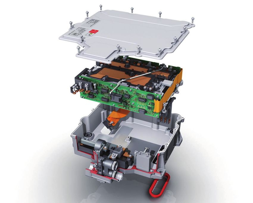
Table of Contents

  Alternative Drives
     Foreword ___________________________________________________________________________________________________________________ 5

  Hybrid and Electric Drive
    Classification of electric drive variants at Audi ___________________________________________________________________________ 7
    Vehicle identification – hybrid and electric vehicles (MHEV/HEV/PHEV/BEV) ____________________________________________ 8
    Technical fundamentals __________________________________________________________________________________________________ 10
    High-voltage technology __________________________________________________________________________________________________ 14
    High-voltage battery ______________________________________________________________________________________________________ 15
    High-voltage cables and connectors ______________________________________________________________________________________ 18
    High-voltage components ________________________________________________________________________________________________ 19
    High-voltage safety concept ______________________________________________________________________________________________ 24
    Warning labels ____________________________________________________________________________________________________________ 26
    Notes for the rescue work ________________________________________________________________________________________________ 28
    Vehicle fire ________________________________________________________________________________________________________________ 40
    Salvage from water _______________________________________________________________________________________________________ 40
    General Safety Information about Lithium-Ion Batteries ________________________________________________________________ 41

  Natural gas drive (g-tron)
    Vehicle identification – Natural gas vehicles _____________________________________________________________________________ 44
    Technical fundamentals __________________________________________________________________________________________________ 45
    Safety installations _______________________________________________________________________________________________________ 49
    Notes for the rescue work ________________________________________________________________________________________________ 52
    Vehicle fire ________________________________________________________________________________________________________________ 54

                                                                                                                                       3
4

Alternative Drives

Foreword

Rescue services study alternative drives on a world-wide scale, due
to the availability of different drive concepts and the increasing
number of vehicle with alternative drives. This applies to the
general processes and procedures of rescue activities after traffic
accidents, but also to the knowledge about the drive concepts
themselves.

In the different countries of the world, the processes and procedu-
res are normally regulated by service regulations or guidelines set
up by legislation or by the rescue organizations themselves. If any
notes on procedures are given in the present rescue guide, these
must be exclusively understood as suggestions.

The main objective of the rescue guideline is to familiarize rescue
services with the drive concepts. Apart from the general presenta-
tion of the technology, the main focus is on the identification and
safety concepts of the different technologies.

                                                                      5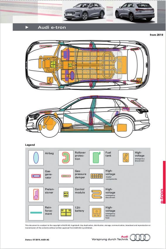
Hybrid and Electric Drive

    e-tron

6
Classification of electric drive variants at Audi
     There are different concepts for mild hybrid, hybrid, and electric vehicles. They differ with respect to the primary
     source of energy, the voltage, the type of traction motor, and the electric driving range.

     A differentiation is made between:
        • Mild-Hybrid Electric Vehicle (MHEV)
        • Full-Hybrid Electric Vehicle (HEV)
        • Plug-In-Hybrid Electric Vehicle (PHEV)
        • Battery Electric Vehicle (BEV)

     The table shows the different electrification concepts.

                                                                                                                       Battery Electric
                             Mild-Hybrid                     Full-Hybrid                  Plug-In-Hybrid
                                                                                                                       Vehicle

Voltage                      12 – 48 V                       200 – 300 V                  300 – 450 V                  300 – 900 V

Electric motor               10 – 15 kW                      20 – 50 kW                   60 – 120 kW                  > 150 kW

                                                                                                                       > 200 km

                                                                                          approx. 50 km
Electric
                                                             approx. 3 km
driving range

Source of energy

                             Q5       A6                                                  A3 e-tron
Examples                                                     Q5 hybrid                                                e-tron
                             Q8       A7                                                  Q7 e-tron
                                                             A6 hybrid                                                e-tron sportback
                             A4       A8                                                  Q5 TFSIe
                                                             A8 hybrid                                                e-tron GT
                             A5                                                           A6 TFSIe
                                                                                          A7 TFSIe
                                                                                          A8 TFSIe

                                                                                                                               r002_006

     Legend for energy sources

      Symbol                     Designation

                                 Traditional fuels e. g. petrol and diesel

                                 Battery operation

                                 Battery operation with charging possibility via socket

                                                                                                                                          7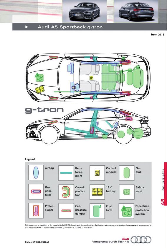
Vehicle identification – hybrid and electric vehicles
    (MHEV/HEV/PHEV/BEV)
    Vehicles with alternative drive concepts can be identified according to different distinguishing characteristics.
    Having this knowledge, rescue services can adapt their activities to the corresponding technology of the vehicles
    involved in an accident.

    Distinguishing characteristics – hybrid and electric vehicles (examples)

    Logo types on the car body exterior

    For Audi, high-voltage vehicles (full, plug-in hybrid and pure electric vehicles) can be identified by the lettering
    “hybrid”, “e-tron”, or by the letter “e” in the technology lettering. An additional feature for battery electric
    vehicles (BEV) is that there is no exhaust pipe.

              The logo types are different between the models, and some can optionally be deselected during vehicle
              configuration. It is also possible that the vehicle owners remove them.

    There are no external differences between mild hybrid vehicles (MHEVs) and conventional Audi vehicles.

                                                      Lettering on the cover of the charging socket
                                                      (right side shown in the example)

                                     r003_112

                                                                                           r001_085

                                                         Technology lettering on the tailgate
                                                                     (or fender)

                                    r001_101

                                                                                            r003_115

8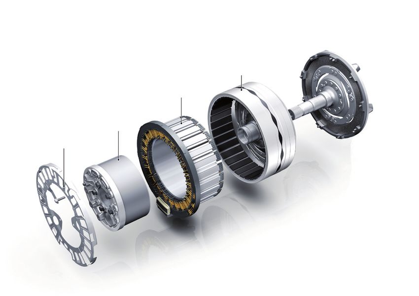
Interior lettering

                                            r001_040                                                                                r003_116
                                                                                                   Lettering on the control panel

         Audi virtual cockpit with e-tron lettering
              and power meter (left display)

                                                           Lettering on the
                                                           door sill strips

                                           r001_086

Lettering on the design cover in the engine compartment and orange coloured high-voltage cable

                                                               Lettering on the design cover in the engine
                                                               compartment

                                            r003_120

Charging socket

         Not every hybrid vehicle variant is equipped with a charging socket. Charging sockets may be located on
         the front of the vehicle, on the front left or right fender or on the rear side of the vehicle.

                                                r003_122                                                                              r003_123
                      Lateral charging socket                                                                 Front charging socket

                                                                                                                                               9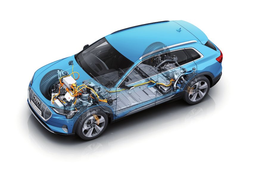
Technical fundamentals
Introduction
A hybrid vehicle (HEV) is driven by a combination of a combustion engine and an electric motor supplied with
current from a high-voltage battery.
The electric motor supports the combustion engine in acceleration phases and is used as a generator in braking
phases in order to charge the high-voltage battery (recuperation).
With plug-in hybrids (PHEV), the high-voltage battery can also be charged via the socket.
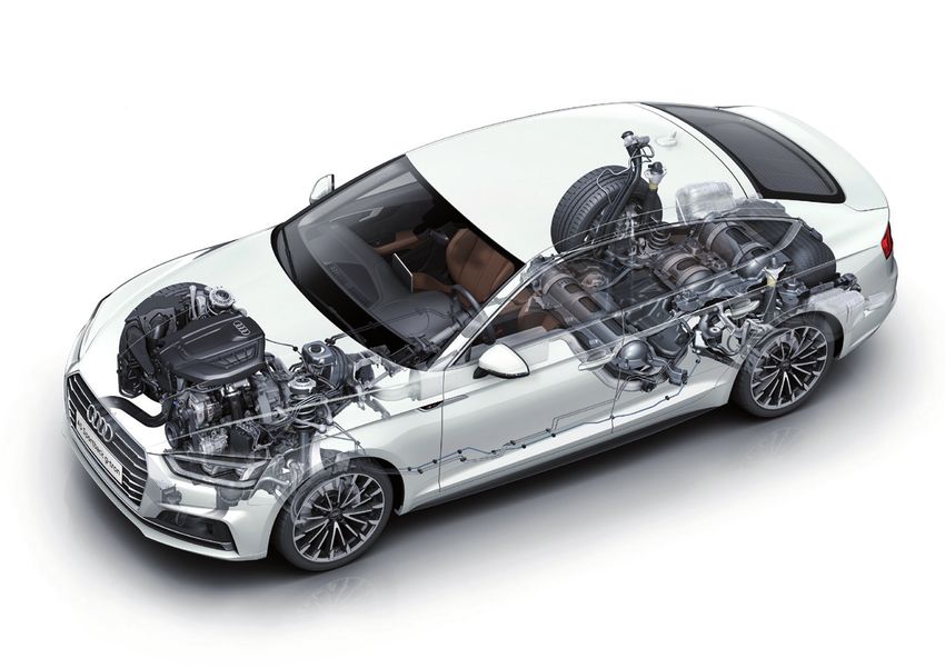
Audi A6 quattro TFSIe as an example of a hybrid vehicle (HEV)
High-voltage battery
fuel tank
Combustion engine
r003_124
10In addition to the classic lead-acid battery, mild hybrid vehicles (MHEVs) have an additional lithium-ion battery
(12 volts or 48 volts) and a starter generator. In principle, this allows functions such as extended recuperation
and support of the combustion engine by the electric motor (recuperation power up to 12 kW). The drive and the
generation of electrical energy is basically carried out by the combustion engine. All units work together with a
belt-driven starter-generator. Purely electric driving is not possible with the Audi MHEV.
• There are no external differences between Audi mild hybrid vehicles (MHEVs) and conventional Audi
vehicles.
• 48 volt lines can be identified by their colour, which is purple. Vehicles with 48-volt technology may have
subsystems installed that operate in the high-voltage range (alternating current greater than 30 volts).
If this is the case, the cables to these systemcomponents can be identified by orange warning colour.
Audi Q8 as an example for a mild hybrid (MHEV)
3.0 TDI Engine
48 V battery
Voltage converter
48 V belt-driven starter-
generator
r003_125
11In the case of purely electric vehicles (BEV), the drive is provided exclusively by one or more electric motors on the
front and/or rear axle. Charging can take place via AC or three-phase sockets, AC wallbox charging stations or DC fast
charging stations. As an optional extra, some vehicles can be equipped with a contactless charging option, with an
induction plate (Audi wireless charging) located under the front engine compartment.
Audi e-tron as an example of a battery electric vehicle (BEV)
Electric front drive High-voltage battery Electric rear drive
r003_126
12Since purely electric vehicles (BEV) are only provided with electrical energy storage, other components of the
engine, such as the coolant pump, are also electrically driven and supplied with power from the 12-volt vehicle
electrical system.
Other auxiliary units, for example the air conditioning compressor are supplied from the high-voltage battery due
to their high energy consumption. Thus, these auxiliary units are also counted as high-voltage components.
Audi e-tron – Overview of high-voltage components
High-voltage charger 1 High-voltage heating 2 Electric rear drive
Charging network
distributor
Charging Control box of the high-
Voltage converter socket 2 voltage battery
Electric front
drive
High-voltage
charger 2
r003_127
Electric air conditioning
compressor
High-voltage Charging socket 1 High-voltage
heating battery
13High-voltage technology
In vehicle technology, the following voltage ranges are designated as “high-voltage”:
• more than 60 V for direct current (DC) and
• more than 30 V for alternating current (AC)
The high-voltage battery, the electric motor, the high-voltage distribution and control unit, the power electronics,
and some auxiliary units operate with high-voltage current.
In the following chapter, the following high-voltage components will be discussed in more detail using examples
from various vehicles:
• High-voltage battery
• Power electronics
• Electric motor
• Auxiliary units e. g. high-voltage air conditioning compressor and auxiliary heater
• High-voltage cables and connectors
• Charging socket
High-voltage air conditioning
The listed components can also be present multiple times in a vehicle. compressor
Schematic outline of a high-voltage system
Direct current (high-voltage DC) Alternating current (high-voltage AC)
Power electronics
(including inverter and
voltage converter)
High-voltage battery Electric motor
(energy accumulator) (power converter)
r001_016
12 V battery
14High-voltage battery
The high-voltage batteries used by Audi are lithium-ion batteries.
The high-voltage battery is arranged in a stable housing in the vehicles, in areas that are low in deformation in
most crash situations.
Hybrid vehicles (HEV): The high-voltage battery can usually be found in the rear of the vehicle.
Battery electric vehicles (BEV): The high-voltage battery is usually mounted centrally under the vehicle as a
load-bearing body component.
In both hybrid and battery electric vehicles (HEV and BEV), the high-voltage battery consists of battery cells
connected in series, which are interconnected to form modules. Several modules are installed, along with the
peripherals, in a metal casing. A potential equalisation line connects the casing to the vehicle.
Depending on the vehicle variant/equipment, the high-voltage battery may consist of several packages.
High-voltage batteries are cooled during operation. Cooling can be carried out with air or liquid and also has the
task of compensating the temperature differences between the individual cells.
The control box of the high-voltage battery is either integrated in the high-voltage battery or is located directly on
the high-voltage battery. The high-voltage battery is connected to the high-voltage system via the control box. In
the event of a crash with belt pretensioner and/or airbag deployment, the control box immediately and automati-
cally disconnects the high-voltage system from the power supply (see “Discharge of residual voltages” on page
25).
Battery system including control box based on the example of the Audi e-tron
Control box of the high-voltage battery
Framework structure
of battery housing
Housing cover
(aluminium)
Housing subframe
Battery frame
Cooling systems
Underride guard
Cell module with
twelve 60 Ah cells
Battery Management
Controller (BMC)
r003_128
15The airbag control unit is wired to the high-voltage battery interlock in the control box. In the event of a serious
collision, the airbag control unit sends signals to the contactor switch. The control box causes the high-voltage
battery to switch off.
If the high-voltage battery has been switched off by a collision, it can only be reactivated by the
workshop.
Control box of the high-voltage battery based on the example of the Audi e-tron
12 V connection
Control unit for rear electric drive
Charger 1, 2. Connection for rear electric
high-voltage heating 1, motor (optional)
voltage converter
Charger 2
High-voltage heating 2
DC quick charging
Control unit for front
electric drive
r003_130
16High-voltage battery with liquid cooling based on the example of the Audi e-tron
The power electronics are connected to the low temperature cooling circuit at the front and the rear axle.
This results in adequate cooling of the individual components inside the power electronics.
Drive motor for electric drive,
Drive motor for electric drive,
rear axle
front axle
Heating and air conditioning unit
Cooler and
condenser
Electric air
conditioning
compressor
r003_130
Refrigerant circuit
Heating circuit
Cooling circuit for high-voltage battery
Cooling circuit for electric drive
train
Air-cooled high-voltage battery based on the example of the Audi Q5 hybrid quattro
High-voltage connection
Cooling
systems
Connection of Maintenance connector
12 V on-board
Safety connector
network
socket
r003_131
Evaporator High-voltage
battery fan
17High-voltage cables and connectors
The cables with the associated high-voltage connectors connect the high-voltage battery to the other high-voltage
components in the engine compartment, as well as the high-voltage components to each other. For example:
:
• Control unit for electric drive (power electronics)
• Electric motor
• Air conditioning compressor
• High-voltage heating
• Charger
• Voltage converter
The high-voltage cables are installed outside of the passenger compartment, i. e. they are underneath the vehicle or
in the engine compartment.
All high-voltage cables and the plugged high-voltage connections have an orange coloured insulation in the visible
areas. Furthermore, additional covers and hoses protect the high-voltage cables against damage. In contrast to the
12 V on-board network, the high voltage system is electrically isolated from the vehicle chassis.
High-voltage cables based on the example of the Audi Q7 e-tron
Automatic transmission High-voltage battery
2.0 TFSI engine
Electric motor
Charging connection
r003_132
Power electronics
18High-voltage components
Control unit for electric drive (power electronics)
The control unit for the electric drive (power electronics) has the task of providing the electric motor with the
necessary three-phase current. In battery electric vehicles (e. g. Audi e-tron) the power electronics are directly
attached to the electric motor and electrically contacted via three phases. Inside the power electronics, the direct
current provided by the high-voltage battery is converted into three-phase current.
Example of the power electronics of the Audi e-tron
Cover
Control electronics
Three-phase current
connection to the
12 V connection
stator windings
Housing
Environmental seal
r003_133
DC voltage connection of
high-voltage battery
19Electric motor
In hybrid vehicles (HEV), the electric motor is located between the combustion engine and the transmission and
provides additional power to the drive. The electric motor replaces the conventional starter of the combustion
engine as well as the conventional generator (alternator) and serves to charge the high-voltage battery.
The operating status of the electric motor is controlled by the engine control unit and the power electronics
system in order to manage the efficiency and power of the drive.
If, for example, the motor control unit detects that the power of the electric motor is sufficient for driving the
vehicle, the combustion engine is switched off.
With battery electric vehicles (BEV), the complete drive and recuperation is performed by the electric motor.
Electric motor based on the example of the Audi Q7 e-tron Separating clutch
Rotor incl. magnets
Stator with coils
Stator carrier and clutch actuator
Guard plate
r003_134
20Electric motor based on the example of the Audi e-tron
Coolant connections
Three-phase connection
with environmental seal
Sensor for coolant temperature
of the front three-phase drive
Rotor
Silver socket with Rotor bearing encoder
earthing ring
Stator cooling jacket
Stator with
2 pole pairs
Front motor temperature sensor
Service drain plug
Resolver cover
r003_135
21High-voltage air conditioning compressor
The electric air-conditioning compressor is integrated into the high-voltage system. A high-voltage cable
connects it to the high-voltage system of the electric drive.
The function of the electric air-conditioning compressor is to cool both the passenger compartment and if
necessary the high-voltage battery when the vehicle is in electric operation or stationary.
With active stationary conditioning, the high-voltage system is active and the high-voltage components
are live.
High-voltage air conditioning based on the example of the Audi e-tron
High-voltage cable connection
r003_137
High-voltage heating
A further auxiliary unit in the high-voltage system is the high-voltage heating.
The function of the high-voltage heating is to heat both the passenger compartment and if necessary the high-
voltage battery when the vehicle is in electric operation or stationary.
With active stationary conditioning, the high-voltage system is active and the high-voltage components
are live.
High-voltage heating based on the example of the Audi e-tron
12 V connection
High-voltage cable connection
r003_138
22Charger for high-voltage battery
The charger is usually installed in the front or rear near the charging socket. Battery electric vehicles (BEV) can
also have several chargers and thus several charging sockets.
The charging currents are transferred to the high-voltage system via induction into coils (galvanic isolation). This
means that there is no conductive connection between the AC network and the high-voltage system in the
vehicle.
Charger for high-voltage battery based on the example of the
Audi e-tron
Switching unit for
high-voltage battery
Charging socket
12 V connection
r003_140
Voltage converter
The voltage converter converts the DC voltage of the high-voltage battery into the 12-volt DC voltage of the vehicle
electrical system. The transmission takes place via induction into coils (galvanic isolation). This means that there is no
conductive connection from the high-voltage system to the 12-volt vehicle electrical system. The power of the voltage
converter is up to 3 kW. If the vehicle is stationary for a longer period of time, the 12-volt-battery is charged by the
high-voltage battery if the latter is sufficiently charged.
This charging process starts automatically. The high-voltage system is active and the high-voltage
components are live.
Control box connection
12 V connection
Voltage converter based on the example of the
Audi e-tron
r003_139
23High-voltage safety concept
The electric components in the vehicle, for example the power electronics the electric motor, the high-voltage
battery and the auxiliary units, such as the electric air conditioning compressor, work in voltage ranges above 60 V
direct current. They are connected to high-voltage lines which are orange in colour, since the voltage level and the
hazard potential is higher compared to the usual direct voltage (DC) of conventional vehicles, which is above 12 or
where applicable 48 volts.
All cables with AC voltage over 30 volts can also be identified by the orange warning colour.
If an insulation fault occurs, for example due to external damage, it is detected by the system; the range of
reactions extends from the mere display of an insulation fault to the shutdown of the entire high-voltage system.
In case of improper handling, the voltage in the high-voltage system poses a potential danger. Thus, there is a
comprehensive safety concept for the vehicle.
The following chapter explains the essential principles of the safety concept.
In case of improper handling of high-voltage components and high-voltage lines, there is danger to life
due to the high voltage and the possible flow of current through he human body.
There is still voltage in a high-voltage battery even after the deactivation of the high-voltage system.
The high-voltage battery must neither be damaged nor opened. Touching it can be fatal!
When working with hydraulic rescue systems, when lifting, securing, towing or pulling the vehicle,
the position of the high-voltage components and high-voltage cables must be observed (see vehicle-
specific rescue data sheet).
Do not touch damaged high-voltage components and/or high-voltage cables!
It cannot be guaranted that all independent protective measures will work after an accident.
High-voltage consumers High-voltage battery
Galvanic separation
The high-voltage system is galvanically separated from
vehicle earth. That means that there is no direct electric
connection between active parts of the high-voltage system
and the car body.
Physical protection
r001_044
The entire high-voltage system is isolated from the 12 V
network and the bodywork and is designed to provide 12 V consumer 12 V battery
protection against physical contact. High-voltage connector Power electronics
Equipotential bonding
The metal housings of all high-voltage components are
conductively connected to the body. This ensures that
no hazardous touch voltage can occur on the metal
housing even in the event of a fault.
High-voltage cables
All high-voltage cables are provided with orange-
coloured insulation. Their orange-coloured sheathing
conveys a clear optical signal. Furthermore, additional
covers and hoses protect the high-voltage cables
against damage.
r001_032
Air conditioning Electric motor
compressor
High-voltage cable
24Short-circuit detection
In the event of a short circuit or overcurrent, the overcurrent protection device (fuse) is tripped and interrupts the
current flow.
Discharge of residual voltages
In case of an accident with airbag and/or belt pretensioner activation or after an unexpected malfunction, the
discharge circuit ensures that the high-voltage system is free from voltage after approximately 20 seconds. By
activating the rescue disconnection point, the high-voltage system is usually also de-energised after approx.
20 seconds (see “Deactivate high-voltage system” on page 33).
After switch-off/deactivation, the high-voltage system is de-energised after approx. 20 seconds!
Isolation monitoring
The isolation resistance of the high-voltage system is periodically tested for isolation monitoring, i. e. for monito-
ring whether the high-voltage system is disconnected from the bodywork.
Malfunctions are indicated with a warning message to the driver, by the lighting of a yellow lamp in the instru-
ment cluster, and an acoustic signal.
Disconnection in case of a crash
Both battery poles are equipped with protection relays (contactors) which are closed for the operation of the
high-voltage system. In case of an accident with airbag or belt pretensioner activation, the high-voltage battery
receives a crash signal to open the protection relays. The protection relays of the high-voltage battery open and
the high-voltage system outside the battery discharges (see “Discharge of residual voltages” on page 25). The
high-voltage connections of the high-voltage battery and all high-voltage components will then be voltage-free.
Beyond the automatic crash deactivation, the vehicle specific rescue data sheets of mild hybrid vehicles (MHEV),
hybrid vehicles (HEV) and battery electric vehicles (BEV) contain information about how to deactivate the high-
voltage system and the vehicle itself.
High-voltage battery
High-voltage “PLUS”
Protection relay
High-voltage “MINUS”
Protection relay
Crash signal
Battery management system Airbag control unit
25Warning labels
All high-voltage components (except for high-voltage cables) are marked with explicit warning labels.
The basic warning labels types are shown below.
• The warning labels with the lettering “Danger” directly mark the high-voltage components.
r003_141
Warning concerning dangerous Requirement mark:
electrical voltage according to Observe instruction
DIN 4844-2 (BGV A8) manual according to
DIN 4844-2 (BGV A8)
Warning: Do not
touch live parts
• Yellow warning label with the electrical voltage warning sign
r003_142
Warning concerning dangerous
electrical voltage according to
DIN 4844-2 (BGV A8)
Warning concerning a Warning:
point of danger according to Do not
DIN 4844-2 (BGV A8) touch live parts
r003_143
Warning concerning Requirement mark:
dangerous electrical voltage Observe instruction
according to DIN 4844-2 manual according to
(BGV A8) DIN 4844-2 (BGV A8)
26• The high-voltage battery is identified by a larger label with corresponding warning notes.
r001_023
Warning concerning Warning concerning
dangerous electrical voltage corrosive substances
Use eye protection
further instructions
Warning concerning
available in user manual
explosive substances
Keep children away
No fire, open light
from batteries
or smoking
Follow the instructions on
the battery, in the
instructions for use and in
the vehicle operating manual
r001_023
Do not open the high- Protect from Maintenance work only
voltage battery humidity by qualified personnel
27Notes for the rescue work
The handling of mild hybrid vehicles (MHEV), hybrid vehicles (HEV) and battery electric vehicles (BEV) involved in
accidents differs in some respects from the handling of petrol or diesel vehicles, e. g. high voltages, lithium-ion
battery.
Knowledge about these differences can be important for the rescue work after car accidents.
Readiness for operation
It can be difficult to determine readiness for operation from the operating noises, because the electric
motor is noiseless.
The pointer of the power meter indicates the current load on the drive; it is usually located on the left-hand side
of the instrument cluster. The drive is active if the power meter in the instrument cluster shows READY (usually
the 9 o’clock position). An inactive drive can be recognized by the power meter in the instrument cluster being
set to “OFF” (for older Audi models “6 o‘clock” position, for newer Audi models “half past 8 o‘clock” position; see
power meter display in the example pictures).
As long as the display in the power meter is not set to “OFF”“, electric motor operation or an automatically
starting combustion engine can still be expected.
The section Technical Assistance (see “Technical assistance” on page 29) describes the process for immobili-
zing and deactivating hybrid and electric vehicles.
Example: older Audi models
Drive switched on,
“READY”
(vehicle ready to drive)
Drive switched off,
“OFF”
r003_184 (vehicle not ready to drive) r003_181
Example: newer Audi models
Drive switched on,
“READY”
(vehicle ready to drive)
Drive switched off,
“OFF”
(vehicle not ready to drive)
r003_180
r003_183
28Technical assistance
Due to the high-voltage safety concept (see on page 24), the potential for risks from the high voltage components
is mitigated. However, residual risks are still present in the event of serious accidents (e.g. with a damaged
battery). Please refer to the chapter “General Safety Information on Lithium-Ion Batteries” on page 41.
In the event of an accident with belt pretensioner and/or airbag activation, the battery protection relays are
opened so that the high-voltage connections of the battery system are de-energised (see “Disconnection in case
of a crash” on page 25). Discharge circuits in other high-voltage components ensure that these are voltage free
after approximately 20 seconds (see “Discharge of residual voltages” on page 25).
After switch-off/deactivation, the high-voltage system is de-energised after approx. 20 seconds!
The procedures of rescue services are generally regulated by corresponding laws, regulations or guidelines.
In addition, further information is provided by the relevant specialist bodies or associations (see e. g. DGUV
Information 205-022: Rescue and fire extinguishing work on passenger cars with alternative drive technology).
The subsequent chapters generally highlight issues which could become significant during the technical assis-
tance after accidents involving vehicles with hybrid or electric drive.
Further information can be found in the FAQ “Accident assistance and recovery for vehicles with high-voltage
systems” issued by the VDA.
Rescue data sheets
Vehicle specific features are described in the rescue data sheets.
The rescue data sheets for vehicles with alternative drive may contain additional information about the handling
of the vehicle. The procedure for vehicle deactivation for these vehicles can be found in the rescue data sheets.
Apart from the indications normally included in the rescue data sheets of conventionally driven vehicles, the
rescue data sheets for hybrid and electric vehicles indicate the position of the high-voltage battery, the cables
between battery and engine compartment, high-voltage components, and the devices for deactivating the high-
voltage system.
In addition to schematic top and lateral view (on the first page), rescue data sheets may include further pages
with the following sections:
• Immobilizing the vehicle
• Switch off the ignition
• Deactivation of the high-voltage system
• Disconnect 12 V and 48 V battery/batteries
• Disconnecting the charging cables
The symbols used in the rescue data sheets applying in particular for hybrid vehicles (HEV) and battery electric vehicles
(BEV) are:
Symbol Designation Symbol Designation
High-voltage battery High-voltage cables and components
High-voltage rescue disconnection Fuse box with fuse for high-voltage
point deactivation
The example on the following page shows the overall structure of rescue data sheet.
29Example of a rescue data sheet
Sheet 1–4 of the rescue data sheets for the Audi e-tron (status 07/2019)
Sheet 1 Sheet 2
r003_175
Sheet 3
r003_176
Sheet 4
r003_174
r003_177
Rescue data sheets for Audi vehicles can be downloaded on the Audi website under:
http://www.audi.de/rettungsleitfaden
The website of the German Association of the Automotive Industry e. V. (VDA) provides an overview of sources
for rescue data sheets from all automobile manufacturers:
https://www.vda.de/en/topics/safety-and-standards/rescue/rescue-data-sheets.html
30Immobilizing the vehicle
According to the situation, the vehicle must be stabilized by appropriate means (slings, chocks etc.).
The electric parking brake is usually located next to or behind the shift/select lever and is activated by pulling it
slightly up.
Electromechanical parking brake r003_151
For vehicles with automatic transmission, the transmission should be set to position “P” (park) using the gear
lever.
r001_038
Setting the gear lever to position “P”
r003_150
Transmission setting P
31Switch off the ignition
The ignition system of vehicles with ignition lock can be switched off by turning the ignition key towards the
passengers “position 0”.
Vehicle with ignition lock r001_045
Vehicles with comfort key do not have a conventional ignition lock. The driver only needs to carry the vehicle
key with him. The button „START ENGINE STOP“ switches the ignition on or off and starts or stops the
engine.
When the ignition is switched on, the button “START ENGINE STOP” must be pressed once in order to switch
the ignition off.
Key “START ENGINE STOP” r003_152
The electric motor is noiseless. The left display in the instrument cluster (power meter) gives feedback as to
whether the electric drive is ready for operation “READY” or switched off “OFF” (see „Notes for the rescue
work“ auf Seite 28).
r003_183 r003_180
Vehicle ready to drive “READY” Vehicle not ready to drive “OFF”
Before you press the key “START ENGINE STOP” ensure that the clutch pedal (manual transmission) or
brake pedal (automatic transmission) is not pressed. Otherwise the engine will start!
r001_102
32Deactivation of the high-voltage system
The high-voltage system of Audi vehicles is deactivated automatically with the activation of the belt pretensio-
ners and/or airbags.
Beyond this, the service rescue data sheets for hybrid and electric vehicles in many cases describe a separate way
of deactivating the high-voltage system.
Hybrid vehicles (HEV) and battery electric vehicles (BEV) usually have a direct current converter (DC/DC) where
the 12-volt system can be supported or fed in by the high-voltage system. Simply switching off the ignition and
disconnecting the 12-volt battery/batteries is not sufficient for high-voltage vehicles to safely deactivate the
high-voltage and 12-volt systems. In this case, the high-voltage system of such a vehicle can be switched off with
one of the additional high-voltage deactivation possibilities (rescue disconnection points).
Rescue disconnection point for high-voltage system
12 V / LV (Low Voltage) Service Disconnect
The low-voltage service disconnect serves as a rescue disconnection point for the high-voltage system in plug-in
vehicles (PHEV) and battery electric vehicles (BEV). The plug has a green casing and a tab for unlocking. A yellow
label at the plug cable clearly indicates that this plug is a rescue disconnection point.
The plug is marked with the symbol “high-voltage rescue disconnection point“ in the rescue data sheet.
Symbol „High-voltage rescue disconnection point“
in the rescue data sheet
Tab
Rescue disconnection plug for the high-voltage system r001_047
Label at the rescue disconnection plug for explaining the r001_052
actuation of the high-voltage disconnection.
33Procedure for deactivating the high-voltage system by means of a rescue disconnection point
1. Locating the rescue disconnection point: see rescue data sheets
Example: location in the engine compartment
r001_050
2. Pull out the red tab of the rescue disconnection point.
r001_089
3. Keep the red tab pressed while pulling out the black plug until it locks.
r001_090
34Fuse box (additional rescue disconnection point for high-voltage system)
In order to offer an additional possibility for deactivating the high-voltage system, more recent
hybrid vehicles (HEV) and battery electric vehicles (BEV) have a fuse in the fuse box.
r001_053
Fuse box with a fuse for deactivating the high-voltage system.
Symbol “Fuse box with fuse for high-voltage
deactivation” in the rescue data sheet
The fuse can be identified by the yellow label. It can be simply pulled out in order to deactivate the high-voltage
system. The fuse box equipped with this fuse is identified in the rescue data sheet with an orange coloured fuse
symbol “Fuse box with fuse for deactivation of the high-voltage system“. Moreover, the rescue data sheet in this
case often includes further information about the exact location and the access to the fuse box.
r003_153
Label on the fuse for deactivating the high-voltage system
35Procedure for deactivating the high-voltage system by pulling out the fuse (example: Audi e-tron).
1. Remove the loading floor from the boot
r003_155
2. Remove the fuse box cover
r003_156
3. Locate the fuse and pull it out
r003_157
For locating the fuse box, please use the rescue data sheets!
36High-voltage service disconnect plug for Q5 hybrid, A6 hybrid, A8 hybrid
The hybrid vehicles (HEV) Q5-hybrid, A6-hybrid, A8-hybrid have a different high-voltage service disconnect plug.
This high-voltage service disconnect plug is located in the middle of the boot floor under a flap that must be
opened. The orange rubber protective cap underneath that must be removed. The exact location can be found in
the rescue data sheets.
The pictures show the direct operation of this high-voltage service disconnect plug. First the lever is pulled to
the rear, then it is turned upwards and pulled out.
1. Pull the lever to the rear. 2. Turn lever upwards and pull out plug in upward direction
r001_083 r001_084
Disconnection of the 12 V battery/batteries
In order to completely disconnect a high-voltage vehicle from the power supply, the 12-volt lead-acid battery
must be disconnected after HV deactivation.
The position of the 12 V battery/batteries can be taken from the rescue data sheet.
If the battery is to be disconnected completely, the ground/minus pole must be disconnected, otherwise there
is a risk of short circuits. The negative pole must be protected against renewed contact (insulation, tying away,
bending away...). If the battery is disconnected, it should be checked whether the vehicle is actually voltage-
free. The extinguishing of the hazard warning lights or the interior lighting can serve as a sign. To completely
disconnect a high-voltage vehicle from the power supply, the 12-volt lead battery must be disconnected after
HV deactivation.
If it is necessary to disconnect the battery, it must be disconnected even if a battery disconnection
element is fitted.
Disconnecting the battery r001_099
37Battery disconnection in mild hybrid vehicles (MHEV, 12 Volt/48 Volt)
For vehicles with 48 V on-board power supply the 48 V vehicle electrical system is automatically deactivated in the
event of accidents involving belt pretensioner and/or airbag activation. The lithium-ion battery of a 12 V MHEV is
also deactivated automatically in the event of accidents involving belt tensioner and/or airbag activation.
In all other cases, the lithium-ion battery (12 V or 48 V) must be disconnected in addition to the 12 V lead-acid
battery in order to deactivate the on-board power supply:
Switch off the ignition before disconnecting the batteries!
In order to reduce the hazard of an electric arc, the following procedure is recommended:
After locating the batteries (see rescue data sheet), the first step is to disconnect the negative pole of the 12-volt
lead battery. In the second step should the lithium-ion battery be disconnected. In this respect, it is recommen-
ded to disconnect the communication plug before disconnecting the negative pole.
For the 48 V lithium-ion battery, there is a residual risk of arcing when the negative pole is disconneted.
Procedure for disconnecting the 12 V and 48 V battery based on the example of the Audi A4
1. Remove the loading floor from the boot 2. Locating the
batteries
r003_158 r003_159
12 V lead-acid battery
48 V lithium-ion battery
3. Loosen the screwed connection of the negative pole of 4. Disconnect the communication connector of the 48 V
the 12 V lead-acid battery lithium-ion battery
r003_160
r003_161
5. Loosen the screwed connection of the negative pole 48 V
lithium-ion battery
For locating the batteries, please use the rescue data sheets!
38Cancelling the charging process
If a vehicle connected to a charging station is involved in an accident, the interruption of the charging process
cannot be ensured.
It is recommended to ensure the interruption of the charging process by pulling the connector from the charging
station. The following working steps are necessary in order to separate the charging cable from the vehicle.
Example: Audi e-tron
2. Press the button on the charging socket and
1. Unlocking the vehicle (e. g. via the radio key) disconnect the charging cable from the vehicle
r003_162 r003_163
Charging procedure emergency unlocking
The new Audi models also feature a charging plug emergency release. The respective procedure is
described in the rescue data sheets.
Procedure for charging plug emergency unlocking based on the example of the Audi e-tron
• Open the front flap
• Open cover 1 in the engine compartment on the relevant charging side
• Remove the yellow loop 2 from the support and pull it carefully
• Disconnect the charging plug
r003_164
Locking and unlocking the vehicle
The current Audi models apply various techniques for locking and unlocking the vehicle.
• Radio key Unlocking by pressing a button on the corresponding symbol of the radio key.
• Comfort key: Unlocking by touching the sensor on the door handle; for this, the comfort key must not be
more than approx. 1.5 m away from the door handle.
• Connect key: Mobile phone of the vehicle owner; for unlocking, the mobile phone must be held centrally
against the door handle of the driver‘s door.
• Connect key card: Key fob in the form of a credit card. To unlock, the key fob must be held centrally
against the door handle of the driver‘s door.
39Vehicle fire
In the case of vehicle fire, a distinction must be made between:
Vehicle fire without high-voltage battery fire:
Identical to a normal passenger car, all common and known extinguishing agents such as water,
foam, CO2 or powder can be used in the “normal” case of fire of a hybrid or battery electric vehicle
(HEV or BEV, where the high-voltage battery does not burn), depending on requirements and/or
availability.
Avoid water ingress into the high-voltage battery!
Vehicle fire with high-voltage battery fire:
In the case of a burning high-voltage battery, it should be extinguished with a water spray if possi-
ble and then cooled. Make sure that plenty of water is used. As possible the water should ingress
into the high-voltage battery.
Take care to use appropriate personal protective equipment (e. g. compressed air breathing appa-
ratus, fire-fighting garments, thermal imaging camera, etc.).
No
Use rescue data sheets to immobilize the
Is the eletric vehicle
vehicle, disable the high-voltage system and
burning?
disconnect the 12 V lead-acid battery.
Yes
No
High-voltage battery Extinguish conventionally (for example: foam).
affected by fire? Avoid water ingress into the battery!
Yes
Extinguish with plenty of
water and cool, as possi-
ble the water should
ingress into the high-
voltage battery! r003_182
Salvage from water
A hybrid vehicle (HEV) or battery electric vehicle (BEV) submerged in water usually doesn’t pose a danger
of an electrical hazard (electric shock).
After recovering the vehicle from the water, the rescue services should drain the water out of the interior.
Subsequently, works on the vehicle can be performed taking into account the mentioned notes for the
rescue work.
Water entering the lithium-ion battery may cause reactions. In this case, observe the general safety
information of the lithium-ion battery.
40General Safety Information about Lithium-Ion Batteries
A lithium-ion battery can react either immediately or with a delay due to severe damage (e. g. crushed, broken or
cracked housing) or exposure to water or fire. Therefore, watch out for any signs (e. g. smoke, heating, noise,
sparks, etc.) while working on a vehicle with a lithium-ion battery which has been damaged in an accident.
If the lithium-ion battery reacts, protective measures and countermeasures must be taken (see “Vehicle fire” on
page 40). After a reaction, the lithium-ion battery must be cooled with water until it has reached approxi-
mately ambient temperature. The use of a thermal imaging camera or an IR thermometer is recommended.
Before transporting the vehicle (e.g. by a towing company), the condition of the lithium-ion battery must be
re-checked. The vehicle may only be loaded and transported if the reaction has ended to such an extent that it
can be assumed that no further reaction is to be expected on the transport route.
The shortest and safest route must be chosen. Passages through tunnels should be avoided.
In some cases it may be appropriate for the towing vehicle to be accompanied by a fire-fighting vehicle.
The vehicle involved in the accident must be parked in a suitable place outside because the lithium-ion battery
still has the theoretical potential to react. The parking space must be marked accordingly (signage/delimitation).
A distance of at least five meters from other vehicles, buildings or combustible objects must be maintained.
The responsible persons of the towing company, the workshops and, if applicable, the disposal companies
must be informed of the special features and risks of the vehicle!
41Lithium-ion battery disconnected from the vehicle
If the high-voltage energy storage system and/or parts of it are disconnected from the vehicle in the event of an
accident, the high-voltage energy storage system poses an electrical, chemical, mechanical and thermal hazard.
In such a case, the following aspects must be considered:
If high-voltage energy storage systems, high-voltage components or high-voltage cables are damaged (e. g. open
components or torn cables), contact with these damaged parts must be avoided!
During unavoidable work in these areas, damaged components or high-voltage energy storage systems must be
covered by electrical insulation.
In this respect, it is recommended to use an appropriate electrically insulating pliant cover (undamaged plastic
foil or other appropriate electrically insulating cover, e. g. according to IEC 61112).
Even when the high-voltage energy storage system has been disconnected from the vehicle, parts of the entire
energy storage system can remain in or on the vehicle.
Separated components of high-voltage energy storage systems must only be picked up from the ground with
electrically insulating equipment!
Leaking electrolytes from damaged high-voltage energy storage systems are usually irritant, flammable and
potentially caustic. Leaking liquids from high-voltage energy storage systems are usually coolants. There are only
small amounts (millilitres) of electrolytes in the individual cells.
Dry leather gloves as well as dry operational gear provide basic protection against electric voltage. Nitrile under-
glove offer additional safeguard against electric voltage and chemicals. For facial protection, the helmet visor
should be lowered at all times when working.
For the transportation of a high-voltage energy storage system disconnected from the vehicle or components of
it, a large metal container is recommended.
The condition of the high-voltage energy storage system must be observed (e. g. smoke, noise, sparks, heating)
and the flooding of the metal container must be prepared.
42Natural gas drive (g-tron)
g-tron
43Vehicle identification – Natural gas vehicles
In most cases, the exterior of natural gas vehicles does not differ from conventionally driven models.
A type designation at the vehicle rear or at the mudguard may be an indication of a natural gas vehicle.
Audi uses the lettering “g-tron” for natural gas vehicles.
If the vehicle does not have a type designation, other characteristics may also point to a vehicle with natural gas
system. For the Audi “g-tron”, for example, these are:
• Natural gas tank nozzle
• Fuel indicator in the instrument cluster
• Identification or lettering in the instrument cluster
The non-existence of these signs however is not a clear indication that the vehicle does not have a natural gas
system.
Sometimes the lettering can be deselected during vehicle configuration; it is also possible that the
vehicle owners remove them.
Distinguishing characteristics – natural gas vehicles
r001_029
r001_028
Natural gas tank nozzle
Type designation “g-tron” at the vehicle rear Open fuel filler flap with
additional natural gas
tank nozzle
r001_070 r001_049
Fuel indicator and lettering in the instrument cluster Lettering on the design cover in the engine compartment
44Technical fundamentals
Introduction
The combustion engine of Audi natural gas vehicles can be operated with natural gas or with petrol. The primary
drive uses natural gas, the petrol tank is a reserve.
Handling natural gas vehicles is generally not more dangerous than handling petrol or diesel vehicles; however,
it differs in some items. Knowledge about these differences can be important for the rescue work after car
accidents.
Natural gas (CNG – Compressed Natural Gas) must not be confused with liquid gas (LPG – Liquefied
Petroleum Gas). Liquid gas and liquid gas installations differ fundamentally from natural gas and natural
gas installations
Audi A5 Sportback g-tron as example of a natural gas vehicle
Natural gas tank
Combustion engine for
natural gas and petrol
Natural gas tanks
Petrol tank
r003_166
45Natural gas as a medium
Physical properties of natural gas
• Natural gas is a colourless, flammable gas (fire class C) which is odourless in original condition.
• For the use in vehicle it is odorized, i. e. an odorant is added to the gas. Thus, a natural gas leak can be detec-
ted already before the lower explosion limit is reached.
• Natural gas is lighter than air (density ratio natural gas/air approx. 0.6) and is thus very volatile in the open!
• Explosion range between 4 volume % and 17 volume %
• Ignition temperature approx. 640 °C
Audi A3 Sportback g-tron – Overview of natural gas components
Fuel filler neck for petrol Gas filler neck
Electronic gas pressure regulator
Natural gas rail
(gas distribution rail)
Natural gas pipe
Fuel lines
(petrol)
Natural gas tanks
Petrol tank
r001_100
46Natural gas technology – “g-tron”
Schematic view of the natural gas system
A natural gas system consists of a high pressure part and a low pressure part. In the high-pressure range, the
system pressure at 15 °C can be up to 200 bar. The low pressure range can be up to 12 bar.
The gas filler neck and the natural gas tanks with the tank shutter valves are located in the vehicle rear. The
gas tubes are installed on the underside of the vehicle and flow toward the electronic gas pressure regulator
in the engine compartment.
From the electronic gas pressure regulator the natural gas is transferred to the natural gas rail from where it
is blown into the engine via injector valves.
Natural gas rail (gas distribution rail) Gas injector valve
Electronic gas Low pressure part
pressure regulator
Natural gas
Distributor unit Check valve
High pressure part
Natural gas tanks
r001_033
Tank shutter valve Gas filler neck
47Natural gas tanks
Fourth natural gas tank
The natural gas tanks on the Audi g-tron models are installed in
the rear on the underside of the vehicle. The new Audi models
A3 g-tron, A4 g-tron and A5 g-tron have an additional natural
gas tank in the rear axle and fuel tank areas. The A4 gtron and
A5 g-tron models have a fourth natural gas tank located in the
rear above the subframe of the rear axle. They are fixed with
tensioning straps to a carrier screwed to the car body.
During filling and emptying, but also due to temperature
variations, the diameter of the natural gas tanks can change by
a maximum of 2 mm. A protective layer is positioned between
r003_178
carrier, tensioning straps and natural gas tanks in order to avoid
damage caused by expansion and contraction.
Tensioning strap with protective layer
Natural gas tanks
Structure
The natural gas tanks are made of layered combined plastics.
Layer structure:
• Interior – layer of gas-tight polyamide
• Intermediate – layer of carbon fibre reinforced plastics (CFRP)
• Exterior layer – glass fibre reinforced plastics (GRP)
(the GRP layer serves in particular for robustness and protection against damage) It also serves to make
damages visible. The fibreglass-reinforced plastic suffers a so-called stress whitening (whitish discoloured
fracturing) under unacceptably high loads.
The binding agent for the used fibre materials is high-strength epoxy resin.
r001_073
Interior layer – gas-tight polyamide
Medium layer – carbon fibre reinforced plastics (CFRP)
Exterior layer – glass fibre reinforced plastics (GRP)
Distributor unit with check valve
Tank shutter valve
48Safety installations
The natural gas installation is built in a way that it is protected against damage. The gas tanks are stable and
heat-resistant.
The high pressure lines are installed outside the passenger compartment. The natural gas components are
equipped with different safety devices. Natural gas vehicles generally have the same degree of safety as
conventionally powered vehicles.
Cylinder valve
Apart from the valves for tank shutting, the cylinder valves have an integrated thermal fuse, a flow rate limiter as
well as a manual shut-off valve.
If it is necessary to shut off the gas tanks for rescue work, each gas tank must be shut off separately.
The manual shut-off valve can be shut with an open-end wrench or a ring wrench No. 5, at the square, by turning
clockwise until reaching the stop.
Gas tank connection
(with flow rate limiter)
Manual shut-off valve
(manual stopcock) Tank shutter valve
r001_027
Thermal fuse Connection for gas line to the engine
49You can also read