GCH I 237 - Cooker hood Manual for installation and use for model - GURARI
←
→
Page content transcription
If your browser does not render page correctly, please read the page content below
Cooker hood
Manual for installation and
     use for model

GCH I 237
Dear customer, we always strive to deliver you faultless products. Should this product not be in perfect condition upon receipt, please contact us immediately. Before you start installing and / or using this product, please read this instruction carefully and be sure to follow the instructions given. Check the delivered parts for completeness and integrity. Should, despite our efforts, any parts be defective or missing, please contact us. You will receive immediate replacement in this case. Never use defective parts! This cooker hood has been constructed for installation and appropriate use in private households. Incorrect installation can damage the appliance and / or your kitchen, as well as it could lead to serious injuries. Do not use parts of the cooker hood or the hood itself for purposes that are not explicitly listed in the manual. No liability is taken over for accidents or damage, due to incorrect installation, use of defective parts or incorrect use of delivered utensils. The supplied mounting parts are not suitable for all ceilings. If you are not sure which material your ceiling consists of and whether it has sufficient load-bearing capacity,be sure to check with an expert. You may need special screws and dowels that are not included. If you do not understand this manual or are concerned about your safety, we recommend the commissioning of an experienced installer for the assembly. Due to the weight and the dimensions of this product we recommend to carry out the installation with 2 persons in any case. We wish you a lot of joy with your new extractor hood. General information Pay attention to the environmentally friendly disposal of the packaging. Please read this manual carefully before use. It contains important information about your safety, installation, commissioning, cleaning and care of your cooker hood. Keep the instructions in a safe place if you need to read them again or need further hints and help in use. Please to not start a damaged device. The device is only suitable for use in private households and not in gastronomy. Assembly and operation may only be carried out in accordance with the instructions in this manual. Our devices comply with the legal requirements for electrical household appliances and may therefore only be repaired by authorized personnel. Besides the dangers involved by inappropriate treatment, we strongly point out, that improper intervention void the warranty. Delivery content - hood body incl. LED lights / motor / control / grease filter /carbon filter - Remote control - Mounting material - Drilling template - Operation manual
Technical specifications
power
-   power consumption in watts              206W
-   Of which lighting (LED)                 2x3W
-   Voltage in volts                        220-240V
-   Fan volume max.                         860 m³/h

Dimensions
-   Height in cm                            20cm
-   Width in cm                             50cm
-   Depth in cm                             50cm
-   Net weight in kg                        11,4kg

specifications

-   Connection with safety plug
-   4-level control
-   LED lighting (2x3W)
-   grease filter (dishwasher-safe)
-   Suitable for recirculation

safety instructions
power supply

The connection is made via a fixed cable with earthing contact plug.

In the case of a required permanent connection, the hood may only be installed by an electrician,
registered at the responsible electricity supply authority.

On the installation side, a disconnecting device (this includes fuses, contactors and circuit breaker
acc. VDE 0730, §7, Part 1) has to be used.

minimum distances

Distance to an electric hob
From the electric cooking area to the lower edge of the hood a
minimum distance of 600mm must be maintained.

Distance to the gas hob
Between gas hobs (upper edge of pot carrier) and lower edge of the
hood a minimum distance of 700mm should comply.

Other notes

Please take care, that hotplates in operation are always covered, so the device will not be damaged
by excessive heat.

When deep-frying under an extractor hood, the appliance used for frying has to be supervised at all
time during operation.

Oils contained in deep fryers may self-ignite due to overheating. Using old and dirty oil can lead to
this even more easily.

We point out that overheating can cause a fire. Furthermore, we point out expressly that flambé
under the hood is not allowed.
For all work on the cooker hood, even when changing the bulb, the hood has to be de-energized (turn
off circuit breaker or remove the screw fuse from the socket). It is also important to follow the filter
change and cleaning intervals.

                If ignored, there is an acute fire hazard due to grease deposits!

Energy-saving tips

Preparation, warming and keeping food warm should always be done in pots or pans with closed lids.

The appliance should be switched off immediately after cooking or, if available, the time-delayed
shutdown be used.

The lighting of the appliance should be switched off after the end of cooking.

Pot sizes should be adapted to the diameter of the cooking zones used.

Use the highest motor speed of the unit only at a high concentration of cooking fumes.

To increase the efficiency of the device, regularly clean the grease filters.

Carbon filters (when used in recirculation mode) should be replaced regularly according to the
manufacturer's specifications.

Parts of the hood

The extractor hood consists of the following parts

                                                                         1 – Fixing Brackets
                                                                         2 – Fixing Brackets cover
                                                                         3 – Telescopic tube
                                                                         4 – Control panel
                                                                         5 – Frame
                                                                         6 – Lighting panel
                                                                         7 – Aluminium filter
                                                                         8 – Decorative glass
Dimension Drawings
Assembly
1 23 4 5 1. examination Before starting the actual installation, the device should be checked. In addition to the control of externally recognizable damage, a function check has to be done. Take out the device from the packing, get rid of all packing materials and put the device with the back on the floor / table. After connecting to a power supply, the lighting as well as the function of each stage should be checked. Please take care that exhaust outlet is open through check. 2. Installation of the hood 1. Using the added installation positioning sticker, mark the required position for the device mounting on the floor/ceiling and paint the necessary holes. Fixtures sent with the set are provided for attachment in massive concrete or stone flooring. If your floor structure is different, the substitution of attachment bolts is required. In such a way, take care of buying appropriate fasteners. 2. Drill 3 holes in the ceiling for fastening the ceiling bracket. 3. Screw the ceiling bracket to the ceiling. 4. Put the cover on the ceiling bracket and fasten it to the ceiling bracket 5. Screw the extension tube into the ceiling bracket 6. Attach the hood to the extension tube 7. Adjust the height of the hood with the tube and secure it with the fixing screw. 8. At the end, connect to the power supply inserting the plug connector into the socket provided for it. If the outlet and power supply output is positioned below the protective plate, then between steps 4 and 5 drill an additional hole through the protective plate, through which you will push the cable for the power supply connection. For this, in case of necessity remove the plug connector to repeatedly mount it in the upper position over the protective plate/cover or connect directly to the power supply. For this engage a professional electrician, who will care about the correct conduction of such an operation and ensuring a safe connection to the power supply. Connection to the power supply should be conducted with the de-energized equipment. The power supply should not be turned on before the conduction of proper isolation.
Usage

Inserting and changing the carbon filter
For recirculation mode we recommend the use of a carbon filter,
which frees the cooking fumes from the smell. The carbon filter
consists of two charcoal-filled cassettes, mounted left and right to
the suction opening of the engine. For mounting please check
picture.

To mount the carbon filter, please take the following steps:

1. First remove the metal grease filters
2. Place the charcoal filter on both sides of the motor in front of the
suction openings
3. In the middle of the filter is a receptacle and on the fan a suitable insert
4. If the filter is seated correctly, you can fix it with a small twisting motion
5. Then reinsert the grease filter

The matching carbon filter for this model is called GE14

Metal grease filter

The aforementioned grease filters are in front of the engine and ensure the absorption of greasy
ingredients from the kitchen haze. The cleaning can be done in the dishwasher. It is recommended to
do this all 14 days (at least once a month). Too long cleaning intervals lead to a blockage of the filter
and thus reduced power.

Cleaning in the dishwasher

The grease filters of your hood are dishwasher safe (55 ° C). However, light discoloration of the metal
can arise. These have no influence on the function of the grease filter and are not considered a
reason for complaint. Put the filters loosely in the dishwasher. Do not bend or pinch them. NOTE: Do
not clean very dirty grease filters together with other dishes.

Cleaning by hand

If cleaned manually, first soak the grease filter extensively in hot rinse liquor, then brush well and
above all, rinse well with clean water. After that drain well. Avoid use of aggressive, acidic or alkaline
detergent. For very stubborn dirt you can resort to commercially available degreaser sprays.
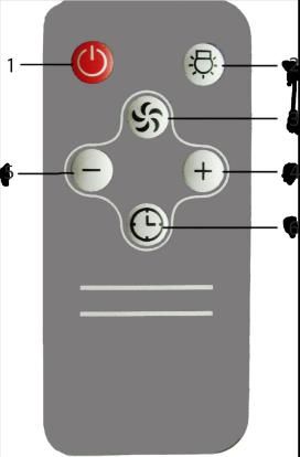
Usage

                              1   - Receiver of remote control
                              2   - Light on / off
                              3   – Speed indicator
                              4   - Increase fan speed
                              5   - Motor on/off

While tuning on the panel of the exhaust hood, press button 5. The panel will open the power, which
was set before it was turned on the last time. Using button 4, you can regulate the power of the
exhaust panel. At this, the panel often turns on the one power above, and, then from the beginning
((0-1-2-3-4-0-1-2…).) Power 0 means that the panel is turned off. Additionally, before the exhaust
panel turns off through the power regulations, it can be turned off at any time by pressing button 5.
Button 2: Turns on and off the lighting.

Timer / off timer

One-time pressing of button 5 during the operation mode of the exhaust hood, activates a 3-minute
timer at that power level.

Remote control

The remote control controls the corresponding functions. Buttons 4 and 5, as well as button 1 turn on
the hood. Button 1 turns off the hood during operation. Button 2 turns the light on or off. With button
6 one can activate the timer and set it as described above. Button 3 does not work on this unit (no
automatic mode).
Cleaning and care
- De-energize the device to clean it.
- Clean the outer parts with mild soapy water. Avoid hot cleaners, brushes, or scrubbing cloths.
- Conventional glass cleaner can be used for the glass surfaces.
It is important to follow the filter changes and cleaning intervals. Failure to comply
can be a fire hazard as a result of fat deposits.
Disposal of the transport packaging
The packaging protects the device against damage during transport. The packaging materials are
selected to be environmentally friendly and recyclable.The return of the packaging into the material
cycle saves raw materials and reduces waste. Your seller will take back the packaging.
Packing parts (e.g., foils, styrofoam) can be dangerous to children. There is danger of suffocation!
Keep packaging parts out of reach of children and dispose them as soon as possible.
Disposal of the old device
Electrical and electronic devices often contain valuable materials. They also contain
harmful substances that are essential to their function and safety were necessary.
Disposal as residual waste can harmful to human health and the environment in case
of wrong treatment. Therefore do not put your old device to residual waste. Instead,
use those collection and return points established by your community or municipality
for return and recovery of electrical and electronic waste.service
If you have any questions or problems, please contact our customer service.
BIB Handelshaus GmbH
Gremberger Str. 18
51105 Köln
Tel.: 036602 473898
Email: service@gurari.de
MO - FR from 8:30 - 16:30
Please have the serial number and the model name of the device ready. The serial number can be
found on the nameplate inside the hood.
All data subject to design changes in the context of technical development of our products.
© 2019 BIB Handelshaus GmbHdeclaration of conformity Product: Extractor hood GCH I 237 Brand: Gurari Manufacturer: BIB Handelshaus GmbH - Gremberger Str. 18 - 51105 Köln - GERMANY The manufacturer hereby declares the conformity of the aforementioned product with the following EU Guidelines: Commission Delegated Regulation (EU) No 65/2014 of 1 October 2013 supplementing Directive 2010/30 / EU of the European Parliament and of the Council with a view to the energy consumption marking of home ovens and range hoods Commission Regulation (EU) No 66/2014 of 14.01.2014 implementing Directive 2009/125 / EC of the European Parliament and of the Council with regard to on the establishment of ecodesign requirements for home baking ovens, cookers and cooker hoods. Proven by compliance with the following European standards: EN61591: 1997 + A1: 2006 + A2: 2011 + A11: 2014 EN60704-1: 2010 + A11: 2012 EN60704-2-13: 2011 EN50581: 2012 EN50564: 2011 BIB Handelshaus GmbH Köln, November 2019
Circuit diagram for the model GCH I 237
hood

mode
                                of the

                louder
                to work
                                Reduced

                                extractor
                                              The lamp

                hood began

Air is poorly

recirculation
drawn in the
                                performance

                The extractor
                                              does not light
                                                               does not work
                                                               Extractor hood
                                                                                Check connection to the electricity supply

                                                                                Check whether the isplay is turned on

                                                                                Check the lamp switch (should be turned
                                                                                on)

                                                                                Check aluminum filter (should be leaned once every
                                                                                month)

                                                                                Check the socket (For the power connection)

                                                                                Check lamps
                                                                                                                                     Possible malfunctions of the extractor hood

                                                                                Check air outlet pipe (for the traction)

                                                                                Check carbon filter (replacement once
                                                                                every 6-12 months)
Dunstabzugshaube
Montage- und Bedienungsanleitung
für das Modell:
GCH I 237Sehr geehrter Kunde, wir sind stets bestrebt, Ihnen einwandfreie Produkte zu liefern. Sollte dieses Produkt bei Erhalt nicht in einwandfreien Zustand sein, setzen Sie sich bitte sofort mit uns in Verbindung. Bevor Sie mit der Installation und/oder der Verwendung dieses Produktes beginnen, lesen Sie sich bitte auf jeden Fall diese Anleitung sorgfältig durch. Kontrollieren Sie die gelieferten Teile auf Voll- ständigkeit und Unversehrtheit. Sollten trotz unserer Bemühungen bei der Kontrolle Teile defekt sein oder fehlen, kontaktieren Sie uns bitte. Sie erhalten in diesem Fall umgehend Ersatz. Benutzen Sie bitte niemals defekte Teile. Diese Dunstabzugshaube ist für die Installation in Privathaushalten mit entsprechender Nutzung konstruiert worden. Eine falsche Installation kann das Gerät und/oder Ihre Küche beschädigen, sowie zu schweren Verletzungen führen. Verwenden Sie die Teile der Dunstabzugshaube und die Haube selbst nicht für Zwecke, die nicht explizit in der Anleitung auf geführt sind. Für Unfälle oder Schäden, die aufgrund einer falschen Installation, dem Benutzen defekter Teile oder einer falschen Nutzung dergelieferten Utensilien entstanden sind, wird keine Haftung übernommen. Die mitgelieferten Montageteile sind nicht für alle Decken geeignet. Wenn Sie sich nicht sicher sind, aus welchem Material Ihre Decke besteht und ob sie über ausreichende Tragfähigkeit verfügt, vergewissern Sie sich unbedingt bei einem Sachverständigen. Sie benötigen unter Umständen spezielle Schrauben und Dübel, die nicht im Lieferumfang enthalten sind. Falls Sie diese Anleitung nicht verstehen oder Bedenken um Ihre Sicherheit haben, empfehlen wir die Beauftragung eines erfahrenen Installateurs für die Montage. Aufgrund des Gewichts und der Abmes- sungen dieses Produktes empfehlen wir die Montage auf jeden Fall mit 2 Personen durchzuführen. Wir wünschen Ihnen viel Freude mit Ihrer neuen Dunstabzugshaube. Allgemeine Hinweise Achten Sie auf umweltgerechte Entsorgung der Verpackung. Bitte lesen Sie diese Anleitung vor Inbetriebnahme sorgfältig durch. Sie enthält wichtige Hinweise zu Ihrer Sicherheit, Montage, Inbetriebnahme, Reinigung und Pflege Ihrer Dunstabzugshaube. Bewahren Sie die Anleitung gut auf. Die Inbetriebnahme eines beschädigten Gerätes ist zu unterlassen. Das Gerät ist nur für die Verwendung in privaten Haushalten und nicht in der Gastronomie geeignet. Montage und Betrieb dürfen nur gemäß den Angaben in dieser Anleitung erfolgen. Unsere Geräte entsprechen den rechtlichen Bestimmungen für Elektrohausgeräte und dürfen daher nur durch hierfür autorisiertes Personal repariert werden. Neben den Gefahren, die bei unsachgemäßer Behandlung entstehen, weisen wir aus drücklich darauf hin, dass bei unsachgemäßem Eingriff der Garantieanspruch erlischt. Lieferumfang - Haubenkorpus inkl. LED Leuchten / Motor / Steuerung / Fettfilter / Kohlefilter / - Fernbedienung - Bohrschablone - Befestigungsmaterial - Bedienungsanleitung
Technische Daten
Leistung
-   Anschlusswert in Watt                 206W
-   Davon Beleuchtung (LED)               2x 3W
-   Spannung in Volt                      220-240V
-   Fördervolumen max.                    860 m³/h

Maße
-   Höhe in cm                            20cm
-   Breite in cm                          50cm
-   Tiefe in cm                           50cm
-   Nettogewicht in kg                    11,4kg

Ausstattung

-   Anschluss mit Schukostecker
-   4-stufige Steuerung
-   LED-Beleuchtung (2x 3W)
-   Fettfilter (spülmaschinengeeignet)
-   Geeignet für Umluft

Sicherheitshinweise

Spannungsversorgung

Der Anschluss erfolgt über eine fest montierte Zuleitung mit Schutzkontaktstecker.

Im Falle eines erforderlichen Festanschlusses darf die Dunsthaube nur durch einen beim zuständigen
EVU (Elektrizitätsversorgungsunternehmen) eingetragenen Elektroinstallateur angeschlossen werden.

Installationsseitig ist eine Trennvorrichtung (dazu zählen Sicherungen, Schütze und LS-Schalter gem.
VDE 0730, §7, Teil 1) vorzusehen.

Mindestabstände

Abstand zum Elektro-Kochfeld
Von der Elektrokochstelle bis zur Unterkante des Haubenkorpus sollte
ein Mindestabstand von 600mm eingehalten werden.

Abstand zum Gas-Kochfeld
Zwischen Gaskochstellen (Oberkante Topfträger) und Unterkante
Haubenkorpus sollten Sie einen Mindestabstand von 700mm
einhalten.

Sonstige Hinweise

Es muss darauf geachtet werden, dass im Betrieb befindliche Kochstellen stets abgedeckt sind, damit
durch starke Hitzeentwicklung das Gerät nicht beschädigt wird.

Beim Frittieren unterhalb einer Dunstabzugshaube ist das zum Frittieren verwendete Gerät während
des Betriebs zu beaufsichtigen.
In Fritteusen enthaltene Öle können sich durch Überhitzung selbst entzünden. Wird verschmutztes Öl
verwendet kann es noch leichter zur Selbstentzündung kommen.
Wir weisen darauf hin, dass durch Überhitzung ein Brand entstehen kann. Desweiteren weisen wir
ausdrücklich darauf hin, dass das Flambieren unter der Dunsthaube nicht erlaubt ist.
Bei allen Arbeiten an der Dunstabzugshaube, auch beim Lampenwechsel, ist die Dunsthaube stromlos
zu machen (Sicherungsautomaten abschalten bzw. Schraubsicherung aus der Fassung heraus-
nehmen). Außerdem ist es wichtig die Filterwechsel- und Reinigungsintervalle einzuhalten.

      Bei Nichtbeachtung besteht aufgrund von Fettablagerungen akute Feuergefahr!

Energiesparhinweise

Zubereitung, aufwärmen und warmhalten von Speisen sollte immer in Töpfen oder Pfannen mit
geschlossenen Deckeln erfolgen.

Das Gerät sollte umgehend nach Kochende ausgeschaltet oder, wenn vorhanden, die zeitverzögerte
Abschaltfunktion in Anspruch genommen werden.

Die Beleuchtung des Geräts sollte nach dem Kochende ausgeschaltet werden.

Topfgrößen sollten an den Durchmesser der verwendeten Kochzonen angepasst sein.

Verwenden Sie die höchste Motorgeschwindigkeit des Gerätes nur bei einer hohen Konzentration von
Kochdünsten.

Zur Steigerung der Effizienz des Geräts, reinigen Sie regelmäßig die Fettfilter.

Kohlefilter (bei Verwendung im Umluftbetrieb) sollten nach Herstellervorgaben regelmäßig
ausgetauscht werden.

Teilebezeichnung

Die Dunstabzugshaube besteht aus folgenden Teilen

                                                           1. Deckenhalterung
                                                           2. Deckenabdeckplatte
                                                           3. Teleskoprohr
                                                           4. Steuerung
                                                           5. Haubenkorpus
                                                           6. Beleuchtung (LED)
                                                           7. Aluminium Fettfilter
                                                           8. Glas
Maßskizzen
Montage
1 23 4 5
1. Prüfung
Vor Beginn der eigentlichen Montage sollte das Gerät geprüft werden. Neben der Kontrolle äußerlich
erkennbarer Schäden ist auch eine Funktionskontrolle durchzuführen. Hierzu ist das Gerät aus der
Verpackung zu nehmen, von allen Verpackungsmaterialien zu befreien und mit der Rückseite auf den
Boden/Tisch zu legen. Nach Verbindung mit einer Stromversorgung kann nun die Beleuchtung als auch
die Funktion der einzelnen Stufen überprüft werden.
2. Montage
1. Mit der beigefügten Bohrschablone markieren Sie die gewünschte Position zur Befestigung an der
Decke und zeichnen die notwendigen Bohrlöcher an. Die mitgelieferten Befestigungen sind für die
Befestigung in einer massiven Beton- / Steindecke gedacht. Haben Sie eine andere
Deckenkonstruktion, ist ggfls. der Austausch der Befestigungsschrauben notwendig. In diesem
Fall besorgen Sie sich bitte entsprechendes Befestigungsmaterial.
2. Bohren Sie die Befestigungslöcher in der Decke passend zur Größe der mitgelieferten
Befestigungen und Schrauben die Deckenhalterung fest an die Decke.
3. Führen Sie nun die Abdeckung über den Deckenhalter und Verschrauben auch diese
4. Fixieren Sie nun das Teleskoprohr in der Deckenhalterung einerseits sowie mit der Haube
andererseits.
5. Regulieren Sie die Höhe der Dunstabzugshaube mit Hilfe des Rohrs indem Sie die
Fixierungsschraube am Teleskoprohr mit einem Imbusschlüssel lösen und nach Einstellung der
gewünschten Höhe (60-90cm) wieder fest drehen.
6. Stellen Sie abschließend die Stromversorgung her, indem Sie das Stromkabel in die dafür
vorgesehen Steckdose stecken. Sollte die Steckdose, Stromzufuhr unterhalb der Abdeckplatte
positioniert sein, Müssen Sie ggfls. zwischen den Schritten 4 und 5 eine zusätzliche Öffnung in
die Abdeckplatte bohren, durch die Sie das Stromkabel führen. Hierzu ist u.U. die Entfernung des
Netzsteckers nötig, um diesen oberhalb der Abdeckplatte wieder anzubringen bzw. einen direkten
Anschluss mit der Stromzufuhr herzustellen. Ziehen Sie hierzu einen Elektrofachmann hinzu, der
auf die ordnungsgemäße Ausführung und Absicherung der Stromzufuhr achtet. Der
Stromanschluss ist in jedem Fall zunächst in stromlosen Zustand auszuführen, bis eine
ordentliche Isolierung hergestellt ist.Betrieb Einsetzen und Wechsel der Kohlefilter Für den Umluftbetrieb empfehlen wir die Verwendung eines Kohlefilters, der die Kochdünste vom Geruch befreit. Der Kohlefilter besteht aus zwei mit Aktivkohle gefüllten Kassetten, die links und rechts auf die Ansaugöffnungen des Motors aufgesetzt und eingedreht werden (s. Abb.) Um die Aktivkohlefilter zu montieren gehen Sie bitte folgendermaßen vor: 1. Entnehmen Sie zunächst die Metall-Fettfilter 2. Setzen Sie den Aktivkohlefilter auf beiden Seiten des Gebläses vor die Ansaugöffnungen 3. In der Mitte der Filter ist eine Aufnahme und auf dem Gebläse ein passender Einsatz 4. Wenn der Filter korrekt sitzt können Sie ihn mit einer kleinen Drehbewegung fixieren 5. Setzen Sie danach den Fettfilter wieder ein Der für dieses Modell passende Kohlefilter heißt GE14 Metall-Fettfilter Die zuvor erwähnten Fettfilter sitzen noch vor dem Motor und sorgen für die Aufnahme der fettigen Bestandteile aus dem Küchendunst. Die Reingung kann in der Spülmaschine erfolgen und sollte alle 14 Tage (min. 1x im Monat) durchgeführt werden. Zu lange Reinigungsintervalle führen zu einer Verstopfung des Filters und damit zu reduzierter Leistung. Reinigung in der Spülmaschine Die Fettfilter Ihrer Haube sind spülmaschinengeeignet (55° C). Dabei können jedoch leichte Verfärbungen des Metalls entstehen. Diese haben keinerlei Einfluss auf die Funktion des Fettfilters und gelten nicht als Reklamationsgrund. Legen Sie die Filter locker in die Geschirrspülmaschine ohne sie zu biegen oder einzuklemmen. HINWEIS: Reinigen Sie sehr stark verschmutzte Fettfilter nicht zusammen mit anderem Geschirr. Reinigung von Hand Bei der Handreinigung die Fettfilter zunächst ausgiebig in heißer Spüllauge einweichen, danach gut abbürsten und vor allem sehr gut mit klarem Wasser ausspülen. Danach gut abtropfen lassen. Sehen Sie von der Verwendung aggressiver, säure- oder laugenhaltiger Reinigungsmittel ab. Für sehr hart- näckige Verschmutzungen können Sie auf im Handel erhältliche Fettlöser-Sprays zurückgreifen.
Bedienung

                                  1:   Fernbedienungssensor
                                  2:   Beleuchtung An/Aus
                                  3:   Anzeige
                                  4:   Stufenschalter
                                  5:   Dunstabzugshaube An/Aus

Zum Einschalten der Haube drücken Sie die Taste 5. Die Haube schaltet sich auf der Stufe ein, die vor
dem letzten Ausschalten eingestellt war. Mit der Taste 4 regulieren Sie die Leistung der Haube. Dabei
schaltet die Haube immer eine Stufe höher und beginnt dann wieder von vorne (0-1-2-3-4-0-1-2…).
Hierbei bedeutet Stufe 0, dass die Haube ausgeschaltet ist. Zusätzlich zum Ausschalten über die
Stufenregulierung kann die Haube jederzeit durch zweimaliges
drücken der Taste 5 ausgeschaltet werden. Die Taste 2 schaltet die Beleuchtung ein bzw. aus.

Timer/Nachlaufautomatik

Ein einmaliges Drücken der Taste 5 während des Betriebes aktiviert einen 3-minütigen Timer auf der
eingestellten Stufe.

Fernbedienung

 Die Fernbedienung steuert die identischen Funktionen. Die Stufenschalter 4 und 5 als auch die On/Off-
 Taste 1 schalten die Haube ein. Die Taste 1 schaltet die Haube im Betrieb aus. Taste 2 schaltet das
 Licht Ein bzw. Aus. Über die Taste 6 können Sie den Timer aktivieren. Die Taste 3 ist bei diesem Gerät
 ohne Funktion.
Reinigung und Pflege
- Zum Reinigen das Gerät spannungslos machen.
- Die äußeren Teile mit milder Spüllauge reinigen. Scharfe Reinigungsmittel, Bürsten, oder Scheuer-
lappen vermeiden.
- Für die Glasflächen kann herkömmlicher Glasreiniger verwendet werden.
Es ist wichtig die Filterwechsel und Reinigungsintervalle einzuhalten. Bei Nichtbeachtung
kann in Folge von Fettablagerung Feuergefahr bestehen.
Entsorgung der Transportverpackung
Die Verpackung schützt das Gerät vor Transportschäden. Die Verpackungsmaterialien sind nach
umweltverträglichen und entsorgungstechnischen Gesichtspunkten ausgewählt und deshalb recycel-
bar. Die Rückführung der Verpackung in den Materialkreislauf spart Rohstoffe und verringert das
Abfallaufkommen. Ihr Fachhändler nimmt die Verpackung zurück.
Verpackungsteile (z.B. Folien, Styropor) können für Kinder gefährlich sein. Es besteht Erstickungsge-
fahr! Bewahren Sie Verpackungsteile außerhalb der Reichweite von Kindern auf und entsorgen Sie
diese so schnell wie möglich.
Entsorgung des Altgerätes
Elektrische und elektronische Altgeräte enthalten vielfach noch wertvolle Materialien.
Sie enthalten aber auch schädliche Stoffe, die für ihre Funktion und Sicherheit
notwendig waren. Im Restmüll oder bei falscher Behandlung können diese der
menschlichen Gesundheit und der Umwelt schaden. Geben Sie Ihr Altgerät deshalb
auf keinen Fall in den Restmüll. Nutzen Sie stattdessen die von Ihrer Gemeinde oder
Kommune eingerichtete Sammelstelle zur Rückgabe und Verwertung
elektrischer und elektronischer Altgeräte.Service
Bei eventuellen Fragen und Störungen wenden Sie sich bitte an unseren Kundendienst.
BIB Handelshaus GmbH
Gremberger Str. 18
51105 Köln
Tel.: 036602 473898
Email: service@gurari.de
MO - FR von 8:30 - 16:30
Halten Sie bitte die Seriennummer und die Modellbezeichnung des Gerätes bereit. Die Seriennummer
finden Sie nach Entnehmen der Metallfilters an der Innenseite des Gerätes.
Alle Angaben vorbehaltlich Konstruktionsänderungen im Rahmen der technischen Weiterentwicklung
unserer Produkte.
© 2019 BIB Handelshaus GmbHKonformitätserklärung Produkt: Dunstabzugshaube GCH I 237 Marke: Gurari Hersteller: BIB Handelshaus GmbH – Gremberger Str. 18 – 51105 Köln – DEUTSCHLAND Der Hersteller erklärt hiermit die Übereinstimmung des vorgenannten Produktes mit folgenden EU Richtlinien: Delegierte Verordnung (EU) Nr. 65/2014 der Kommission vom 1. Oktober 2013 zur Ergänzung der Richtlinie 2010/30/EU des Europäischen Parlaments und des Rates im Hinblick auf die Energieverbrauchskennzeichnung von Haushaltsbacköfen und - dunstabzugshauben Verordnung (EU) Nr. 66/2014 der Kommission vom 14.01.2014 zur Durchführung der Richtlinie 2009/125/EG des Europäischen Parlaments und des Rates im Hinblick auf die Festlegung von Anforderungen an die umweltgerechte Gestaltung von Haushaltsbacköfen, -kochmulden und -dunstabzugshauben. Nachgewiesen durch Einhaltung folgender europäischer Standards: EN61591:1997 + A1:2006 + A2:2011 + A11:2014 EN60704-1:2010 + A11:2012 EN60704-2-13:2011 EN50581:2012 EN50564:2011 BIB Handelshaus GmbH Köln, im November 2019
Schaltplan für das Modell GCH I 237
Im
                              Die
                                             Die

ist die
                              wurde

schlecht
                                             geht nicht

                              schlechter

               Die Haube
                                                           Die Haube

                                             Beleuchtung

               wurde lauter

Saugleistung
                              Saugleistung
                                                           arbeitet nicht

Umluftmodus
                                                                            Überprüfen Sie die elektrische Verbindung

                                                                            Überprüfen Sie ob der Motor arbeitet

                                                                            Überprüfen Sie ob die Beleuchtungstaste
                                                                            leuchtet

                                                                            Überprüfen Sie den Fettfilter (Reinigung min. 1x im
                                                                            Monat)

                                                                            Überprüfen Sie ob Strom an der Steckdose
                                                                            vorhanden ist

                                                                            Überprüfen Sie die Lampen
                                                                                                                                  Möglicherweise auftretende Störungen

                                                                            Überprüfen Sie ob Luft am Abluftstutzen
                                                                            ausgeblasen wird

                                                                            Überprüfen Sie den Kohlefilter (wechsel alle
                                                                            6-12 Monate)
CAPPA da cucina
Guida di installazione e uso
per modello
GCH I 237Caro compratore, ci sforziamo sempre di offrivi i prodotti perfetti. Se questo prodotto non è in perfette condizioni al momento della consegna, Vi preghiamo di contattarci immediatamente. Prima di iniziare l’installazione e / o l’utilizzo di questo prodotto, si prega di leggere attentamente questo manuale e assicurarsi di seguire le istruzioni fornite. Verificate la completezza e l’integrità delle parti fornite. Se qualche dettaglio, nonostante i nostri sforzi, è difettoso o mancante, Vi preghiamo di contattarci. In questo caso, sostituiremo immediatamente le parti. Non usare mai parti difettose! Questa cappa è destinata all’installazione e all’uso corretto in abitazioni private. Un’installazione errata può danneggiare l’apparecchio e/o la Vostra cucina e può causare gravi danni. Non utilizzare parti della cappa o la cappa stessa per scopi non espressamente indicati nel manuale. Non siamo responsabili per incidenti o danni dovuti a un’installazione impropria, uso di parti difettose o uso improprio degli accessori forniti. Le parti di fissaggio non sono adatte a tutti i soffitti. Se non si è sicuri del materiale di cui è fatto il soffitto e se ha una capacità portante sufficiente, consultare uno specialista. Potreste aver bisogno di viti e tasselli speciali non inclusi. Se Voi non capite questo manuale o siete preoccupati per la propria sicurezza, Vi consigliamo di installare una cappa con un installatore esperto. Considerando il peso e le dimensioni di questo prodotto, si consiglia di installare da due persone in ogni caso. Desideriamo che il lavoro della cappa Vi abbia procurato molta gioia. Informazioni generali Prestate attenzione allo smaltimento ecologico dell’imballaggio. Si prega di leggere attentamente questo manuale guida prima dell’uso. Esso contiene informazioni importanti sulla sicurezza, installazione, messa in servizio, pulizia e cura della cappa. Conservare il manuale in un luogo sicuro se è necessario rileggerlo o se sono necessari ulteriori suggerimenti e assistenza. Non accendere un dispositivo danneggiato. L’apparecchio è destinato esclusivamente all’uso in abitazioni private e non in gastronomia. L’installazione e il funzionamento possono essere eseguiti solo conformemente alle istruzioni contenute nel presente manuale. I nostri dispositivi sono conformi ai requisiti della legislazione sugli apparecchi elettrici, pertanto possono essere riparati solo da una persona autorizzata. Oltre al rischio di cattivo trattamento, sottolineiamo che la manomissione impropria renderà la garanzia come nullitа. Contenuto di fornitura - Corpo della cappa, incl. luci a LED / motore / unità di controllo / filtro antigrasso / filtro al carbone - Telecomando - Dima di foratura - Materiale di montaggio - Manuale operativo
Specificazioni tecniche
    Potenza
-   consumo di energia in watt                  206W
-   da cui illuminazione (LED)                  2x 3W
-   tensione in volt                            220-240 V
-   Prestazioni del ventilatore max.            860 m³/h
    Dimensioni
    -   Altezza in cm                           20cm
    -   Larghezza in cm                         50m
    -   Profondità in cm                        50cm
    -   Peso netto in kg                        11,4kg

    Caratteristiche

-   Collegamento con una spina di sicurezza
-   Controllo a 4 fasi
-   Lampadine (2x 3W)
-   filtro antigrasso (lavabile in lavastoviglie)
-   Adatto per aria di ricircolo

    Requisiti di sicurezza

    Alimentazione

    La connessione avviene tramite un cavo con una spina di contatto messa a terra.

    Nel caso di una connessione permanente richiesta, la cappa può essere installata solo da un
    elettricista, registrato presso l'autorità responsabile della fornitura di energia elettrica.

    Durante l’installazione deve essere utilizzato un dispositivo di disconnessione (inclusi fusibili, contattori
    e interruttori automatici secondo VDE 0730, §7, parte 1).

    Distanze minimali

    Distanza dalla cucina elettrica
    Mantenere una distanza di almeno 600 mm dalla superficie di
    cottura elettrica al bordo inferiore della cappa.

    Distanza dalla cucina a gas
    È necessario mantenere una distanza minima di 700 mm tra
    le cucine a gas (bordo superiore) e il bordo inferiore della
    cappa.

    Altre note

    Si prega di fare attenzione che le piastre elettriche in funzione siano sempre coperte, quindi il
    dispositivo non sarà danneggiato da un calore eccessivo.

    Quando si frigge sotto una cappa aspirante, l’apparecchio utilizzato per friggere deve essere
    costantemente controllato durante il funzionamento.

    Gli oli contenuti nelle friggitrici possono autoinfiammarsi a causa del surriscaldamento. L’uso di olio
    vecchio e sporco può portare a questo ancora più facilmente.

    Segnaliamo che il surriscaldamento può causare un incendio. Inoltre, segnaliamo espressamente che
    la cottura a flambé sotto la coppa accesa non è consentito.
Per tutti i lavori sulla cappa, anche quando si cambia una lampadina, la cappa deve essere
diseccitata (spegnere l’interruttore automatico o rimuovere il fusibile a vite dalla presa). È anche
importante seguire la sostituzione del filtro e gli intervalli di pulizia.
Se ignorare queste note, esiste un grave pericolo di incendio a causa di depositi di grasso!
Suggerimenti per il risparmio energetico
La preparazione, il riscaldamento e il mantenimento del cibo caldo devono sempre essere eseguiti in
pentole o padelle chiuse con coperchi.
L’apparecchio deve essere spento immediatamente dopo la cottura o, se disponibile, utilizzare lo
spegnimento ritardato.
L’illuminazione dell’apparecchio deve essere spenta alla fine della cottura. Le dimensioni delle pentole
devono essere adattate al diametro delle zone di cottura utilizzate.
Utilizzare la massima velocità del motore dell’apparecchio solo ad un’alta concentrazione di fumi di
cottura. Per aumentare l’efficienza del dispositivo, pulire regolarmente i filtri antigrasso.
I filtri al carbone (se utilizzati in modalità di ricircolo) devono essere sostituiti regolarmente secondo le
specifiche del produttore.
Parti della cappa
La cappa è composta dalle seguenti parti:
1. Staffa di fissaggio
2. Copertura staffa di montaggio
3. Tubo telescopico
4. Interruttore delle modalità di unzionamento
5. Corpo della cappa
6. pannello di illuminazione
7. Filtro del grasso
8. Vetro decorativoDisegno di dimensioni
Installazione
1 23 4 5 1. Controllo Prima dell’installazione, controllare il dispositivo. Oltre a controllare per i danni esterni, è necessario eseguire un'ispezione di funzionamento. Rimuovere il dispositivo dalla confezione, mettere da parte tutto il materiale di imballaggio e posizionare il dispositivo con lo schienale sul pavimento / tavolo. Dopo il collegamento alla fonte di alimentazione, è necessario verificare l’illuminazione e il funzionamento di ogni fase. Assicurarsi che l’adattatore uscita di scarico sia aperto mentre si fa i controlli. 2. Installazione della cappa 1. Con l'aiuto della dima allegata per perforare i fori, contrassegnare la posizione desiderata per il montaggio del dispositivo sul solaio / soffitto e tracciare i fori necessari. I fissaggi inviati con aggiunta di dispositivo sono destinati al fissaggio in un massiccio solaio di cemento o di camino. Se si dispone di un design di solaio diverso, in questo caso è necessario sostituire i bulloni di montaggio. In questo caso, fare attenzione ad acquistare il materiale di fissaggio appropriato. 2. Praticare 3 fori nel soffitto per montare la staffa da soffitto. 3. Avvitare la staffa da soffitto al soffitto. 4. Mettere il coperchio sulla staffa da soffitto e fissarlo alla staffa da soffitto 5. Avvitare il tubo telescopico nella staffa da soffitto. 6. Fissare la cappa al tubo telescopico 7. Regolare l’altezza della cappa con l’aiuto del tubo e fissarlo con il vite di fissaggio. . 8. Infine, collegare l'alimentatore inserendo il connettore nella presa prevista. Se la presa e quindi la tensione di alimentazione sono posizionate più in basso della piastra di protezione, allora tra i punti 4 e 5 è necessario preforare un ulteriore foro nella piastra di protezione, attraverso la quale si collegherà il cavo per collegare la tensione di alimentazione. Per fare ciò, scollegare la spina stessa se necessario, in modo da rimontarla questa volta nella posizione superiore sopra la piastra / coperchio di protezione, o per creare un collegamento diretto della tensione di alimentazione. Per fare ciò, è necessario assumere un elettricista che si occupi del corretto funzionamento e garantisca un corretto collegamento sicuro della tensione di alimentazione. In ogni caso la tensione di alimentazione deve essere collegata allo stato dei dispositivi senza corrente, non inserire la tensione di alimentazione fino a quando non viene effettuato il corretto isolamento.
Utilizzo

Inserimento e sostituzione del filtro al carbone

Per la modalità di ricircolo si consiglia l'so di un filtro a carbone,
che libera dall’odore di fumi di cottura. Il filtro al carbone è
costituito da due cassette con carbone, montate a sinistra e a
destra sull’apertura di aspirazione del motore. Per il montaggio,
vedi l’immagine.

Per montare il filtro a carbone, procedere come segue:

1.   Rimuovere innanzitutto i filtri antigrasso a metallo
2.   Collocare il filtro al carbone su entrambi i lati del motore davanti alle aperture di aspirazione
3.   Al centro del filtro c'è una presa e sulla ventola un inserto adatto
4.   Se il filtro è inserito correttamente, è possibile fissarlo con un piccolo movimento di torsione
5.   Quindi reinserire il filtro antigrasso

Il filtro a carbone corrispondente per questo modello si chiama GE14

Filtri antigrasso a metallo
I suddetti filtri per separatori di grassi si trovano davanti al motore e forniscono l’assorbimento degli
ingredienti grassi dai vapori della cucina. La pulizia può essere effettuata in lavastoviglie. Si consiglia
di farlo ogni 14 giorni (almeno una volta al mese). Intervalli di pulizia eccessivi comportano
un’ostruzione del filtro e quindi una riduzione della potenza.

Pulizia in lavastoviglie

I filtri antigrasso della Vostra cappa sono lavabili in lavastoviglie (55 ° C). Tuttavia, può insorgere un
leggero scolorimento del metallo. Questi non influiscono sulla funzione del filtro antigrasso e non sono
considerati come motivo di reclamo. Mettete i filtri liberamente in lavastoviglie. Non piegarli né
pressarli. NOTA: non pulire i filtri antigrasso molto sporchi insieme ad altri piatti.

Pulizia a mano
Se pulite a mano, immergete prima il filtro antigrasso ampiamente in un liquido caldo, quindi
spazzolate bene e, soprattutto, sciacquate bene con acqua pulita. Dopo questo asciugateli bene.
Evitate l’uso di detergenti aggressivi, acidi o alcalini. Per lo sporco molto ostinato è possibile ricorrere a
spray sgrassanti disponibili in commercio.
Utilizzo

                                  1   -   Sensore a infrarossi
                                  2   -   La luce è accesa / spenta
                                  3   -   Schermo
                                  4   -   Aumentare la velocità
                                  5   -   Ventilatore è acceso / spento

Per accendere il pannello della cappa, premere il pulsante 5. Il pannello si accenderà al livello impostato
prima dell'ultima accensione. Con il pulsante 4 è possibile regolare la potenza del pannello della cappa.
In questo caso il pannello viene sempre acceso di un gradino più in alto e poi tutto ricomincia (0-1-2-3-
4-0-1-2…). Il livello 0 significa che il pannello è spento. Oltre allo spegnimento tramite il comando a
gradini, il pannello della cappa può essere spento in qualsiasi momento premendo due volte il pulsante
5. Pulsante 2: accende o spegne l’illuminazione.

Timer / timer off

Premendo il pulsante 5 una volta durante il funzionamento la cappa attiva un timer di tre minuti in
questa/ corrente fase.

 Telecomando

 Comando remoto controlla le relative funzioni. I pulsanti 4 e 5 e il pulsante 1 attivano l'aspirazione. Il
 pulsante 1 spegne l'aspirazione durante il funzionamento. Il pulsante 2 accende o spegne la luce.
 Tramite il pulsante 6 si può attivare il timer e settarlo come descritto sopra. Il pulsante 3 è disattivato
 su questo impianto (assente il regime automatico)
Pulizia e cura
- Diseccitate il dispositivo per pulirlo.
- Pulite le parti esterne con acqua saponata delicata. Evitate detergenti caldi, spazzole o panni per la
pulizia.
- È possibile utilizzare un detergente per vetri convenzionale per le superfici in vetro.
È importante seguire le sostituzioni al filtro e gli intervalli di pulizia. La mancata osservanza
può essere un rischio di incendio a causa di depositi di grasso.
Smaltimento dell’imballaggio di trasporto
L’imballaggio protegge il dispositivo da danni durante il trasporto. I materiali di imballaggio sono
selezionati per essere ecologici e riciclabili. Il ritorno dell’imballaggio nel ciclo dei materiali consente
di risparmiare materie prime e ridurre gli sprechi. Il venditore riprenderà la confezione.
Le parti dell’imballaggio (ad es. Pellicole, polistirolo) possono essere pericolose per i bambini. C’è
pericolo di soffocamento! Tenere le parti dell’imballaggio fuori dalla portata dei bambini e smaltirle
il prima possibile.
Smaltimento del vecchio dispositivo
I dispositivi elettrici ed elettronici contengono spesso materiali preziosi. Contengono
inoltre sostanze nocive che sono essenziali per la loro funzione e la sicurezza. Lo
smaltimento come rifiuto residuo può danneggiare la salute umana e l’ambiente in
caso di trattamento errato. Pertanto, non gettare il vecchio dispositivo in rifiuti
residui. Utilizzate invece i punti di raccolta e restituzione stabiliti dalla propria
comunità o comune per la restituzione e il recupero di rifiuti elettrici ed elettronici.Manutenzione
In caso di domande o problemi, si prega rivolgersi al servizio clienti
BIB Handelshaus GmbH
Via Gremberger, 18
51105 Cologna
Tel.: 036602 473898
E-mail: service@gurari.de
Lunedì – venerdì dalle 8:30 alle 16:30
Si deve conoscere il numero di serie e nome del modello dell’apparecchio.
Il numero di serie si può trovare nella targhetta dei dati dentro il coperchio.
Tutti i dati concernenti il design, possono essere alterati nel contesto dell’elaborazione della nostra
produzione.
© 2019 BIB Handelshaus GmbHDichiarazione di conformità Prodotto: Cappa GCH I 237 Marchio: Gurari Produttore: BIB Handelshaus GmbH – via Gremberger, 18 - 51105 Cologna - Germania Il produttore con la presente dichiara la conformità del prodotto sopra indicato alle Regole dell’UE: La Regolazione delegata della Commissione (UE) n. 65/2014 del 1° ottobre 2013 Direttiva integrativa 2010/30/EU del Parlamento Europeo e del Consiglio ai fini della marcatura del consumo di energia dei fornelli e cappe di cucina in economie private. Regolazione della Commissione (UE) n. 66/2014 del 14.01.2014 La Direttiva dell’introduzione nell’effetto 2009/125/EU del Parlamento Europeo e del Consiglio circa i requisiti di progettazione ecologica dei forni, fornelli e cappe in economie private. È stata provata la conformità agli standard europei seguenti: EN61591: 1997 + A1: 2006 + A2: 2011 + A11: 2014 EN60704-1: 2010 + A11: 2012 EN60704-2-13: 2011 EN50581: 2012 EN50564: 2011 BIB Handelshaus GmbH Cologna, Novembre 2019
Schema elettrico principale per il modello
               GCH I 237
alto
Nella
la cappa
funziona
ricircolo,
evacuata
diminuita
la potenza
l’aria viene
tumore più
la lampada
modalità di
debolmente
funziona con
la cappa non
non è accesa
della cappa è
Controllare i collegamenti elettrici
Controllare che lo schermo sia
acceso
Controllare l’interruttore della
lampada (deve essere acceso)
Controllare il filtro di alluminio (deve essere
pulito una volta ogni mese)
Controllare la presa (se c’è tensione)
Possibili guasti nel funzionamento
Controllare le lampadine
Controllare il tubo dell’uscita dell’aria
(deve essere tiraggio)
Controllare il filtro a carbone (cambio
1 volta ogni 6-12 mesi)Hotte aspirante de cuisine
Manuel d'installation et
d'utilisation
GCH I 237Cher client, Nous nous efforçons de vous livrer les produits de qualité irréprochable. Si ce produit n'est pas en parfait état au moment de livraison, veuillez nous contacter immédiatement. Avant de commencer l'installation et/ ou utilisation de cet appareil, veuillez lire attentivement ce manuel et assurez-vous de suivre les instructions. Vérifiez l'intégrité des pièces livrées. Au cas ou , malgré nos efforts, certaines pièces sont défectueuses ou manquantes, veuillez nous contacter. Dans ce cas, vous recevrez un remplacement immédiat. N'utilisez jamais de pièces défectueuses! Cette hotte a été conçue pour être installée et utilisée de manière appropriée dans des ménages privés. Une installation incorrecte peut endommager l'appareil et/ ou votre cuisine, cela pourrait également entraîner des blessures graves. N'utilisez pas la hotte ou les pièces de la hotte à des fins qui ne sont pas explicitement indiqués dans le présent manuel. Nous nous déchargeons de toute responsabilité pour les accidents ou les dommages dus à une installation incorrecte, à l'utilisation de pièces défectueuses ou à une utilisation incorrecte de l'appareil. Les pièces de montage fournies ne conviennent pas à tous les plafonds. Au cas où vous ignorez le matériel composant votre plafond et s'il a une capacité de charge suffisante, veuillez consulter un spécialiste. Vous pouvez avoir besoin de vis et de chevilles spécifiques qui ne sons pas inclus dans le matériel livré. Si vous ne comprenez pas ce manuel ou si vous vous êtes préoccupé par votre sécurité, nous vous recommandons de faire appel à un installateur expérimenté pour le montage. Tenant compte du poids et des dimensions de l'appareil, nous vous recommandons d'effectuer l'installation à deux. Nous vous félicitons avec l'acquisition de votre nouvelle hotte aspirante. Informations générales Faite attention à bien trier l'emballage. Veuillez lire attentivement ce manuel avant utilisation. Il contient des informations importantes sur votre sécurité, l'installation, la mise en service, le nettoyage et l'entretien de votre hotte. Conservez les instructions dans un endroit sûr si vous avez besoin de les relire ou si vous avez besoin de conseils supplémentaires et d'aide à l'utilisation. Veuillez ne pas utiliser un appareil endommagé. Cet appareil convient uniquement pour une utilisation dans les ménages privés et nons dans la gastronomie. Le montage et le mise en service ne peuvent être effectués que conformément aux instructions de présent manuel. Nos appareils sont conformes aux exigences légales des appareils électroménagers et peuvent être réparés uniquement par le personnel autorisé. Outre les dangers liés à un traitement inapproprié, nous soulignons fortement qu'une intervention inappropriée annule la garantie. Contenu de la livraison - corps de la hotte incluant éclairage LED / moteur / éléments de commandes / filtre à graisses / filtre à charbon - Télécommande - Gabarit de perçage - Matériel de montage - Manuel d’utilisation
Caractéristiques techniques
consommation
-   consommation d'énergie en Watt            206W
-   Donc l'éclairage (LED)                    2x 3W
-   Tension en volts                          220-240V
-   Débit maximal de ventilateur              860 m³/h

Dimensions
-   Hauteur en cm                             20cm
-   Largeur en cm                             50cm
-   Profondeur en cm                          50cm
-   Poids net en kg                           11,4kg

spécifications techniques

-   Câble électrique avec prise de sécurité
-   commandes sur 4 niveaux
-   éclairage LED (2x 3W)
-   filtre à graisses (lavable au lave-vaisselle)
-   Convient pour les cuisines sans évacuation d’air vers l’extérieur

instructions de sécurité
consommation électrique

La connexion se fait via un câble fixe avec une prise de contact de mise à la terre.

Dans le cas d'une connexion permanente requise, la hotte ne peut être installée que par un
électricien agréé auprès de l'autorité d'approvisionnement en électricité compétente.

En ce qui concerne l'installation, un dispositif de déconnexion (comme les fusibles, les
contacteurs et un disjoncteur, selon VDE 0730, §7, Part 1) doit être utilisé.

distances minimales

Distance à une plaque de cuisson électrique
La distance minimale à respecter entre la plaque de cuisson
électrique et le bord inférieur de la hotte doit être de 600
mm.

Distance à la cuisinière à gaz
La distance minimale à respecter entre une cuisinière à gaz (depuis
le bord supérieur du porte-pot) et le bord inférieur de la hotte doit
être de 700 mm.

Commentaires

Veuillez à ce que les plaques chauffantes en fonctionnement sont toujours couvertes, afin que
l'appareil ne soit pas endommagé par une chaleur excessive.

Si vous faites de la friture sous une hotte aspirante, veuillez surveillez à tout moment l'appareil
utilisé.

Les huiles utilisées dans les friteuses peuvent s'enflammer spontanément en raison d'une
surchauffe. L'utilisation d'une huile déjà utilisée ou sale peut provoquer cela encore plus facilement.
Nous soulignons qu'une surchauffe peut provoquer un incendie. De plus, nous tenons à souligner
expressément que faire du flambé sous la hotte est strictement interdit.

Pour tous les travaux sur la hotte, même pour un changement de l'ampoule, la hotte doit être mise
hors tension (éteignez le disjoncteur ou retirez le fusible de la prise). Il est également important de
respecter les intervalles de changement et de nettoyage des filtres.

         Si cela n'est pas respecté, il y a un risque important d'incendie dû aux dépôts
                                             de graisses!

Conseils sur l'économie d'énergie

La cuisson, le réchauffement et le maintien les aliments au chaud doit toujours être fait dans des
casseroles ou des poêles avec les couvercles fermés.

L'appareil doit être éteint immédiatement après la cuisson ou, si cette fonction est disponible, vous
pouvez utiliser le temps d'arrêt différé.

L'éclairage de l'appareil doit être éteint une fois la cuisson terminée. La taille

des casseroles utilisées doit être adaptée au diamètre des zones de cuisson

utilisées.

Veuillez utiliser la vitesse la plus élevée uniquement en cas d'une forte concentration

de fumées de cuisson dans la cuisine. Pour augmenter l'efficacité de l'appareil,

nettoyez régulièrement les filtres à graisses.

Les filtres à charbon (lorsque l'appareil est utilisé en mode d'évacuation fermée) doivent être
remplacés régulièrement selon les indications du fabricant.

Les composants de la hotte

La hotte aspirante comprend les parties suivantes :

                                                              1. Support de montage
                                                              2. Support de montage du couvercle
                                                              3. tube télescopique
                                                              4. Commutateur de mode
                                                              5. Corp de la hotte aspirante
                                                              6. Panneau d'éclairage
                                                              7. Filtre à graisses
                                                              8. Verre décoratif
Dimensions
Montage
1 23 4 5 1. Contrôle Avant de commencer l’installation, vérifiez votre appareil. En plus du contrôle extérieur des dommages de l’appareil, un contrôle fonctionnel est également nécessaire à faire. Retirez tous les emballages de l’appareil et placez l'appareil avec le dos sur une surface plate (par terre ou sur une table). Branchez ensuite votre appareil à une prise électrique et vérifiez l’éclairage, ainsi que la fonction de chaque étape. Veuillez vous assurer que la sortie d’échappement d'air est ouverte lors de la vérification. 2. Installation de la hotte 1. À l'aide du gabarit de perçage fourni, marquez la position souhaitée pour la fixation au plafond et marquez les trous de perçage nécessaires. Les fixations fournies sont destinées à la fixation dans un plafond massif en béton / pierre. Si vous avez une construction de plafond différente, le remplacement des vis de fixation est nécessaire. Dans ce cas, veuillez-vous procurer le matériel de fixation approprié. 2. Percez trois orifices dans le plafond pour la fixation de la console de plafond. 3. Vissez la console de plafond vers le plafond. 4. Placez le couvercle sur la console de plafond et la fixez sur la console de plafond 5. Vissez le tube téléscopique à la console de plafond 6. Accrochez la hotte vers le tube téléscopique 7. Réglez la hauteur de la hotte avec l’aide du tube et la fixez par la vis fixant. 8. Enfin, connectez l'alimentation électrique en branchant le câble d'alimentation dans la prise fournie. Si la prise d'alimentation est positionnée sous la plaque de recouvrement, vous devrez peut-être le faire. Percez une ouverture supplémentaire dans la plaque de recouvrement entre les étapes 4 et 5 à travers laquelle vous passerez le câble d'alimentation. Pour ce faire, il peut être nécessaire de retirer la fiche d'alimentation afin de la remettre en place au-dessus du couvercle ou d'établir une connexion directe à l'alimentation électrique. Consultez un électricien qualifié qui s'assurera que l'alimentation électrique est correctement mise en œuvre et protégée. Dans tous les cas, la connexion électrique doit d'abord être effectuée dans un état sans courant jusqu'à ce que l'isolation correcte soit établie.
You can also read