Global-Map-Registered Local Visual Odometry Using On-the-Fly Pose Graph Updates - HVRL
←
→
Page content transcription
If your browser does not render page correctly, please read the page content below
Global-Map-Registered Local Visual
        Odometry Using On-the-Fly Pose Graph
                      Updates

 Masahiro Yamaguchi1(B) , Shohei Mori2 , Hideo Saito1 , Shoji Yachida3 ,
                        and Takashi Shibata3
 1
     Information and Computer Science, Keio University, Yokohama 223-8522, Japan
                       {yamaguchi,saito}@hvrl.ics.keio.ac.jp
     2
        Institute of Computer Graphics and Vision, Graz University of Technology,
                                  8010 Graz, Austria
                             shohei.mori@icg.tugraz.at
                          3
                            NEC, Kawasaki 211–8666, Japan
                                 s-yachida@nec.com

        Abstract. Real-time camera pose estimation is one of the indispensable
        technologies for Augmented Reality (AR). While a large body of work in
        Visual Odometry (VO) has been proposed for AR, practical challenges
        such as scale ambiguities and accumulative errors still remain especially
        when we apply VO to large-scale scenes due to limited hardware and
        resources. We propose a camera pose registration method, where a local
        VO is consecutively optimized with respect to a large-scale scene map
        on the fly. This framework enables the scale estimation between a VO
        map and a scene map and reduces accumulative errors by finding cor-
        responding locations in the map to the current frame and by on-the-fly
        pose graph optimization. The results using public datasets demonstrated
        that our approach reduces the accumulative errors of naı̈ve VO.

        Keywords: Visual Odometry        · Graph optimization · Structure from
        motion · Location-based AR.

1     Introduction
Real-time camera pose estimation is an essential function for Augmented Reality
(AR) systems in registering 3D content to the scene. The size of a scene can
vary from a desktop to a city scale and depending on the scale, the feasible
hardware for camera pose estimation also changes. Since outside-in tracking
becomes impractical in wide areas, AR systems with wide scalability rely on
inside-out tracking.
    Stand-alone inside-out tracking systems, such as Visual Odometry (VO) and
Simultaneous Localization and Mapping (SLAM), use vision sensors, i.e., a cam-
era, to achieve pixel-wise registration in the user’s view. However, VO accumu-
lates errors over time and drifts from the original location. Although SLAM can
c Springer Nature Switzerland AG 2020
L. T. De Paolis and P. Bourdot (Eds.): AVR 2020, LNCS 12242, pp. 299–311, 2020.
https://doi.org/10.1007/978-3-030-58465-8_23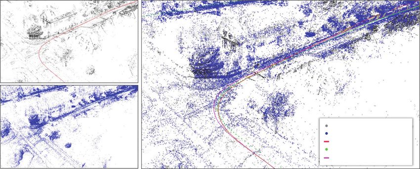
300 M. Yamaguchi et al.
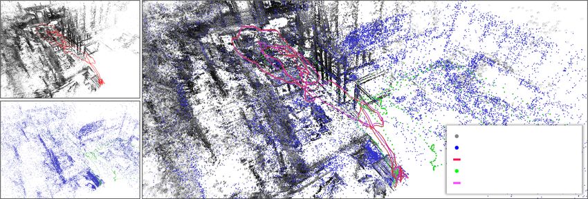
Point Cloud (VO)
Point Cloud (Scene Map)
Trajectory (VO)
Camera Pose (Scene Map)
Registered Trajectory (Output)
Fig. 1. Registering a locally growing VO (a) to a globally optimized scene map (b).
Since both maps are in individual scales and individual coordinate systems, the pro-
posed method registers the VO to the scene map by reducing such differences at run
time (c). This allows the location-based AR system using the VO to retrieve AR con-
tents registered in the scene map.
mitigate this error by detecting re-visits in a scene and attempts to cancel the
accumulated errors. Nevertheless, before the loop close detection, SLAM also
suffers from the drift. This makes location-based AR error-prone, especially in
wider areas, since the drifted position triggers unrelated AR content.
Since VO and SLAM provide only temporal personalized scene tracking to
AR, scene registered content can be created only at the runtime and will be
paused in the next trial. Therefore, to enable a consistent AR experience on a
daily basis, AR developers need to register their content to pre-built common-
scene maps, and AR systems are required to match their executing VO or SLAM
to the scene map to access pre-built content. Consequently, the scene map cre-
ation must be done in a stage earlier than the user’s AR experience.
To satisfy these AR-specific needs, we propose a new camera pose registration
system using VO in conjunction with a pre-built scene map. Our method enables
feeding a pre-built scene map to a VO. In this method, a locally running VO can
refer to the preserved scene map’s information immediately after the execution.
This means that our tracking system can bootstrap the VO within the scene
map scale and update the current camera pose with a pose graph optimization
without closing the VO’s trajectory loop by itself. Figure 1 shows snapshots of
a globally optimized scene map (Fig. 1(a)) and a locally growing VO map on
different scales (Fig. 1(b)). Our method re-calculates the scale difference of the
VO and the scene map on the fly and continues updating the VO map when the
scene map is available (Fig. 1(c)). Our contributions are summarized as follows:
– We propose a camera tracking system that automatically registers the local
user’s VO map to a pre-built scene map relying only on a color camera. With
this, the user can receive AR content in the scene map within the adjusted
scale immediately after the method finds a matching between the current
undergoing VO map and the world map. Additionally, this can mitigate drift
errors that would be accumulated over time with solely the VO.
Global-Map-Registered Local Visual Odometry        301

– We present an approach to match the scale between the VO map and a scene
  map to provide scale-consistent content in the AR space.
– We provide the results of quantitative evaluations, demonstrating the supe-
  riority and the limitations of our method.

    One can find several similar approaches that combine VO and a pre-built
scene map [12,15]. The major difference is that such approaches rely on the
inertial measurement unit (IMU), i.e., visual-inertial odometry (VIO) [13], for
stability and for the absolute scale factor, whereas ours does not, i.e., VO receives
only a video stream.

2   Related Work
Camera pose estimation methods for AR using a color camera are divided into
three major approaches: VO, SLAM, and pre-built map-based tracking.

VO and SLAM: VO [3,5] is a camera tracker that gives pixel-wise content
registrations in the AR view. As VO is designed to optimize the poses and the
map with respect to several of the latest frames, it suffers from drift errors over
time. SLAM [4,7,11] is an alternative designed to reduce drift errors with a
global optimization process such as Bundle Adjustment (BA) and a loop closure
scheme [19].
    Regardless of the global optimization process, both approaches use tempo-
rally built maps to track the scene. The reason behind this is that VO and SLAM
provide different scale factors in every trial depending on how the user moves the
camera. This prevents AR applications fetching pre-built content. VIO is one of
the choices used to overcome the scale difference issue, as it provides a real-scale
map. Several approaches [12,15] have already proposed such methods in the last
few years. GPS can also be a tool to obtain a real-scale map in SLAM [21]. Con-
trary to these sensor-fusion approaches, we solely rely on a monocular camera to
minimize the hardware required for AR systems. To this end, we use a pre-built
map and estimate a scale from the locally running VO and the pre-built scene
map.

Pre-built Map-Based Tracking: Location-based AR applications must have
an interface to link the camera pose and the location, to trigger location-specific
AR content. One popular approach to achieve this is to register the camera within
a preserved scene map to have access to the map registered content. Landmark
database-based approaches use maps built with Structure from Motion (SfM)
to estimate camera poses in the map by linking observed feature points and
those in the database map [9,18,22], therefore, lacking feature point matching
results in the tracking failures. Our approach uses VO, with which we continue
tracking the camera using its online local map. PTAMM can re-localize the
camera in multiple local maps distributed in a scene [2]. This approach is only
applicable to room-scale scenes, where no loop closure scheme is required, due
to the limited scalability of the core SLAM method. Our method can scale from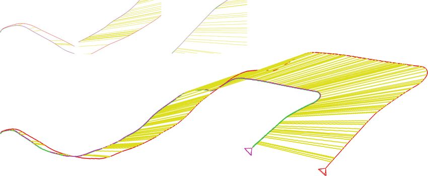
302        M. Yamaguchi et al.

    Offline process           Online process
                                                                           VO
     Color Image Collection                           SfM-scale
                                  Color Image
                                                     RGBD Image
                                                                   VO-scale Map & Poses

     Map Constructor (SfM)        BoW Matcher         PnP Solver
                                                                      Map Optimizer

                                    SfM-scale          SfM-scale        SfM-scale
         SfM-scale Map
                                   Depth Map             Pose        VO Map & Poses

                                   Fig. 2. System overview.

a desktop environment to a city-scale environment with the empowerment of the
state-of-the-art VO.

3      Registering Local VO to a Global Scene Map

We propose a method capable of registering and refining a trajectory of a locally
running VO using a scene map optimized in advance, potentially with higher
accuracy than what naı̈ve VO and SLAM can provide. To this end, we propose
a framework that provides an SfM scale in ongoing VO and propose to match
and optimize the VO trajectories in an SfM-scale map.

3.1      System Overview

Figure 2 shows an overview of the proposed method. Given a global map of a
scene G that contains frame depth maps in the scale sSfM , poses, and Bags of
Binary Words (BoW) database [6], a camera starts exploring the scene, and VO
estimates the trajectory in its own scale map sVO . When the system detects the
best match of the incoming frame to a frame in G, it calculates the corresponding
pose in the SfM scale. Given a collection of such poses, our method optimizes
the current VO trajectory through graph optimization. Although this approach
best fits VO, we could replace VO with SLAM without losing generality. SLAM
is a framework that includes map optimization by itself, so VO is the minimum
configuration for the proposed method.

3.2      Global Scene Map Generation Using SfM

Given M images, we construct a map G using SfM before actual VO tracking
starts. As the maps generated by SfM [17] are known to be accurate compared
to the ones created by SLAM and VO due to its global optimization nature,
we do not update the global map G during VO tracking. On the other hand,
the VO map is optimized at runtime to match the map to the stable global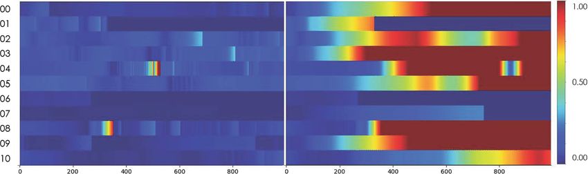
Global-Map-Registered Local Visual Odometry      303

map. Such a global map consists of color frames I SfM , depth maps at each frame
DSfM , and associated frame poses T SfM . Hereafter, we denote the ith (< M )
color frame, depth frame, and their pose as IiSfM ∈ I SfM , DiSfM ∈ DSfM , and
TSfM
  i    ∈ T SfM , respectively. In addition, we use BoW with ORB features [14],
FiSfM
        ∈ F SfM , detected at each frame Im to relate the frames in the global
map I SfM with the frames given to VO, i.e., we define our global map as G ∈
{I SfM , DSfM , T SfM , F SfM }.

3.3   Bootstrapping VO with a Global Scene Map Scale
As the baseline length at the initialization of a monocular VO is unknown in most
cases, such a VO randomly estimates a camera trajectory and a corresponding
map in an arbitrary scale given at a bootstrapping stage [3]. Although a stereo
VO [24] can use a calibrated baseline length between the two cameras to obtain
a scale, fitting the scale to that for a global map is another issue, unless these
scales are calibrated in the real unit [13,23]. Instead of bootstrapping VO from
scratch, we use DSfM to feed the scale of G, i.e., sSfM , to VO. Given a VO
keyframe I KF ⊂ I VO and its BoW vector F KF , we search a depth frame DiSfM
that has a frame index, i, satisfying the following condition:

                         argmin |FiSfM − F KF |2 > tBoW ,                     (1)
                            i

where tBoW is a user-given threshold.
   Once such a frame index is found, we unproject the depth map DiSfM to
obtain 3D points. Detecting and matching feature points in IiSfM and I KF gives
their 2D–2D correspondences, and the unprojected 3D points at such feature
points in IiSfM give 3D–2D correspondences between IiSfM and I KF . Solving the
perspective-n-point (PnP) problem with a RANSAC robust estimator gives the
pose of the keyframe I KF , T KF , in scale sSfM . Finally, the depth map at the
current keyframe DKF is calculated as follows:

                     DKF = π −1 (TKF (TSfM )−1 π(DSfM )),                     (2)

where π(·) is an operator that unprojects a 2D point with depth to 3D space
and π(·)−1 performs the inverse operation. Such a depth map DKF is passed to
the bootstrapping procedure in VO. Consequently, VO, after this, estimates the
camera poses and the map in sSfM .

3.4   Keyframe Pose Refinement
After bootstrapping VO, our method refines upcoming keyframe poses to fit
them to the global map G using the same strategy as that in bootstrapping.
As not all keyframes would receive corresponding frames in G, non-matched
keyframes need to be refined using a different approach. For such keyframes,
we use pose graph optimization [10]. Figure 3 shows how we establish the pose
graph.
304 M. Yamaguchi et al.
Fig. 3. Pose refinement using graph optimization with pre-registered poses in a global
map. The circles with a cross are the camera poses of a global map, and the gray circles
are the camera poses of VO (T0 , ..., TN ). The red arrow shows that the ith frame of VO
matches one of the poses in the global map. The right image shows the matching result
represented. As a result, the poses of VO are refined to the locations where dotted
circles (T 0 , ..., T N ) exist. (Color figure online)
For keyframes matched to I SfMi of I SfM , we estimate their poses by directly
obtaining 3D–2D correspondences and solving the PnP problem in the scale of
G, as described in Sect. 3.3. For the other keyframes, we connect them with
their previous keyframes. Consequently, we construct an edge, ei,i−1 , for the ith
keyframe, as follows:
−1 KF −1 KF
ei,i−1 = ((TKF
i−1 ) Ti )((T̂KF
i−1 ) T̂i ), (3)
where T̂KF
i represents the ith estimated pose from the PnP solver and TKF i
represents the ith estimated pose from VO.
Every time a new match is detected and the pose estimation by a PnP solver
is conducted, our pose graph is renewed by inserting the estimated pose. We
optimize the following pose graph by using the g2o algorithm [10]:
F(x) = eT
i,i−1 Ωi,i−1 ei,i−1 , (4)
i∈N
x∗ = argmin F(x), (5)
x
where N is the last matched keyframe index, x∗ = (T 0 , ..., T N ) is an array of
refined poses, and Ωi,i−1 is an information matrix. We optimize Eq. 5 with the
Levenberg Marquardt algorithm. Note that the first keyframe pose, i.e., T0 , is
fixed, whereas the other poses are not.
3.5 Current Camera Pose Refinement
As only the keyframe poses are refined so far, we need to calculate the current
pose as a relative pose from the last keyframe with a given scale sVO→SfM in
order to obtain the pose along with the scale sSfM :
|tKF
i − tKF
0 |2
TVO
i := sVO→SfM TVO KF
ij Tj with sVO→SfM = , (6)
|ti − tKF
KF
0 |2Global-Map-Registered Local Visual Odometry 305
is the ith translation vector, t i is the ith refined translation vector,
KF
where tKF
i
and |.|2 is the represented L2 norm. TijVO is the reference pose from frame j to
frame i via VO, and s is the scale-error-resolving factor. The blue circle in Fig. 3
represents this current camera pose refinement step.
4 Evaluations
We validated the proposed method using public dataset of two different kinds,
and compared our results to those of state-of-the-art approaches (DSO [3] and
ORB-SLAM2 [11]). Through the evaluations, we demonstrate how the proposed
approach is capable of mitigating accumulative drift errors in VO with the help
of pose updates using a scene map.
4.1 Implementation
We used COLMAP [17] as SfM to generate a global scene map G consisting of
camera poses T SfM and depth images DSfM . The depth images DSfM are calcu-
lated based on both photometric and geometric consistencies [16]. In addition, we
calculated ORB features F SfM of the input frames and stored them in a DBoW3
database [6]. To mitigate the drift errors for VO in the dataset of sequential
images, we took every third frame for SfM.
We used DSO [3] as VO and extended the framework to implement our app-
roach. DSO originally had two threads: a camera pose estimation thread and
a visualization thread. In addition to them, we implemented a BoW match-
ing thread and a pose graph optimization thread. The pose graph optimization
thread is implemented in a similar way as in the direct sparse odometry with a
loop closure (LDSO) [7]. Further, we used g2o [10] for graph optimization.
4.2 Datasets
We evaluated the proposed method using the EuRoC MAV Dataset [1] and
the KITTI dataset [8]. The EuRoC MAV dataset provides 11 sequences con-
taining stereo images, synchronized IMU readings, and ground-truth camera
trajectories. The sequences are captured in three different scenes consisting of
five sequences in Machine Hall, three sequences in a Vehicon Room 1, and three
sequences in Vehicon Room 2. In each scene, we used one sequence to generate a
global map and the rest for VO. We used the right camera images as an input for
both SfM and VO. The KITTI dataset provides 22 stereo sequences of driving
cars. In the dataset, 11 sequences (00–10) provide the ground truth trajectories.
We utilized left views to generate global scene maps and fed the right views to
VO. Further, we used the first 1,000 images for evaluation to exclude frames
that could trigger loop closures in SLAM.306 M. Yamaguchi et al.
Point Cloud (VO)
Point Cloud (Scene Map)
Trajectory (VO)
Camera Pose (Scene Map)
Registered Trajectory (Output)
Fig. 4. Registering a VO map (a) to a scene map (b) in the KITTI dataset sequence
05. (c) Both maps are matched regarding the coordinate systems and the scales.
4.3 Evaluation Method
We validated the proposed method by measuring the absolute trajectory error
(ATE) in each dataset. We evaluated the ATE only in VO keyframes since such
keyframes are the ones we optimize. We should note that we optimized the
resultant trajectories with respect to the ground truth using Sim(3)-alignment,
i.e., Umeyama Alignment [20]. We discuss this Sim(3)-aligned ATE results in
Sect. 4.4. Although Sim(3)-alignment is de-facto-standard post-processing for
VO and SLAM evaluations [3,11], such ATE does not represent frame-by-frame
errors that the users actually observe in the AR view. Therefore, we conducted
another evaluation where we gave an adjusted scale to DSO in the bootstrapping,
to evaluate growing ATE over time. We describe this evaluation in Sect. 4.5.
4.4 Results of ATE with Sim(3)-Alignment
Tables 1 and 2 show the results of Machine Hall and Vehicon Rooms 1 and 2,
respectively. The cross marks in the tables show there were not enough matching
points between the input and global map frames and our method failed to boot-
strap our VO. Figure 1 and Fig. 4 show qualitative comparisons of a global scene
map, a VO map, and a registered VO map in the global scene map in EuRoC
Machine Hall and in KITTI sequence 00–10. Table 3 summarizes ATE in the
four scenes in the KITTI dataset and Fig. 5 shows Sim(3)-aligned trajectories
of the KITTI dataset.
The proposed method obtained the best RMSE in one sequence of the EuRoC
dataset. On the other hand, the proposed method obtained the best RMSE
in the eight sequences of the KITTI dataset. In case that the camera could
frequently observe revisiting, such as in the EuRoC dataset, we consider that
ORB-SLAM2 tends to obtain good BA and loop closure results. Therefore, our
refined trajectories could not achieve better scores than ORB-SLAM2 could in
such scenes. However, in the KITTI dataset, we could surpass ORB-SLAM2Global-Map-Registered Local Visual Odometry 307
Table 1. ATE on EuRoC Machine Hall (m)
Sequence Ours DSO ORB-SLAM2
Global map MH01 MH02 MH03 MH04 MH05 – –
MH01 – 0.0812 0.0448 × × 0.0532 0.0448
MH02 0.0564 – 0.0473 × × 0.0438 0.0303
MH03 0.0845 0.1035 – 0.2014 × 0.1903 0.0393
MH04 × × 0.1562 – × 0.2043 0.1160
MH05 × × 0.1394 × – 0.1374 0.0468
Table 2. ATE on EuRoC Vehicon Room 1 and 2 (m)
Sequence Ours DSO ORB-SLAM2
Global map V101 V102 V103 – –
V101 – 0.0970 × 0.1550 0.0877
V102 0.0689 – × 0.2031 0.0601
V103 1.0732 × – 0.4356 ×
Global map V201 V202 V203 – –
V201 – 0.0812 × 0.0678 0.0623
V202 0.0970 – × 0.1084 0.0557
V203 × × – 1.3888 ×
Table 3. ATE on KITTI Training Sequences (m)
Sequence Ours DSO ORB-SLAM2
00 3.101 7.165 9.780
01 5.768 326.065 518.853
02 5.926 93.200 15.100
03 0.824 1.215 0.810
04 0.233 0.490 1.097
05 5.797 16.614 21.103
06 6.203 48.641 15.908
07 4.925 15.653 16.772
08 5.994 13.554 17.375
09 0.104 0.165 0.090
10 2.797 7.429 3.652308 M. Yamaguchi et al.
Sequence 00 Sequence 03
Sequence 05 Sequence 08
Fig. 5. Sim(3)-aligned trajectories of KITTI sequences 00, 03, 05, and 08
in the scores because most sequences are straight roads, and revisiting does not
occur in the sequences. Overall, we observed that our approach achieved a similar
level of accuracy as those in ORB-SLAM2 and obtained better scores than DSO
in most of the cases. Again, notice that for DSO and ORB-SLAM2, we used
Sim(3)-alignment after calculating all the trajectories, while for our approach,
we did not proceed such a post-processing at all.
The main limitation in the accuracy of our approach comes from the depen-
dency on BoW. Our pose refinement processing is based on BoW-based fea-
ture matching. Therefore, we cannot obtain any benefits from the preserved
scene map if the appearance of the scene that the system is currently observing
is different from the one in the scene map. This happens when environments
change according to various external factors (e.g., weather changes, dynamicGlobal-Map-Registered Local Visual Odometry 309
The proposed method DSO
Fig. 6. The error accumulation with the proposed method and DSO in the KITTI
dataset. We calculated ATE between the estimated poses and the ground truth poses
at runtime. While our approach can keep the ATE significantly lower than the naı̈ve
DSO, we see some spikes before the pose updates occur.
Ours
Naïve DSO (Scaled at the bootstrapping)
COLMAP Camera Pose
Matching Constraints
Start
Goal
Fig. 7. The results of the camera pose plots of COLMAP (scene map), Naı̈ve DSO,
and our approach in KITTI sequence 10. Our trajectory keeps the poses next to the
COLMAP poses. Naı̈ve DSO travels far from the COLMAP poses even though the
scale is initialized in the same manner as our approach.
objects, day-night lighting changes) and prevent applying our approach to out-
door scenes. MH04, MH05, V103, and V203 in the EuRoC dataset are cases such
that BoW does not work well due to differences in the illumination between the
global maps and test sequences.
4.5 Results of ATE Without Sim(3)-Alignment
One of the advantages of our approach is that it can fit the scale of VO to
the global scene map automatically. We finally demonstrate how the trajectory
errors accumulate in naı̈ve DSO and how our approach can reduce the errors.
VO, in our framework, initializes the scale factor using a SfM depth map and310 M. Yamaguchi et al.
updates it when the systems find a matching between an observed frame and
preserved frame in the scene map. For fair comparisons, we bootstrap the naı̈ve
DSO with the SfM depth map but do not update the scale in the later frames.
Figure 6 shows the frame-by-frame differences in ATE of each tracking and Fig. 7
shows the trajectory results of the proposed approach and the naı̈ve DSO.
One interesting observation from Fig. 6 is that the color gradients of our
approach show some spikes even though it achieves lower errors across the frames.
We observed these spikes as jumps right after the pose updates when VO is pulled
back to the global scene map every time VO matches one of the global scene
map frames. However, though this process, our approach significantly reduces
the amount of accumulative errors of VO. This should be troublesome for AR
applications. For example, annotations registered in the map will always shift
in the AR view when the matching happens. Thus, we should design new pose
update rules to change these system-oriented pose updates to the user-oriented
pose updates to reduce the user’s mental load.
5 Conclusion
In this paper, we proposed a method to register a locally running VO to an
existing scene map. Our approach refines upcoming camera poses by referring a
prepared global scene map from SfM, and registers the estimated VO trajectory
to the scene map using pose graph optimization on the fly. This approach enables
the reuse of a pre-built map, which potentially contains AR contents, to solve
the scale ambiguity problem of VO and to reduce accumulative errors of VO.
The results using public datasets demonstrated that our approach could reduce
the accumulative errors of VO.
References
1. Burri, M., et al.: The EuRoC micro aerial vehicle datasets. Int. J. Robot. Res. 35,
1157–1163 (2016)
2. Castle, R., Klein, G., Murray, D.W.: Video-rate localization in multiple maps for
wearable augmented reality. In: International Symposium on Wearable Computers,
pp. 15–22 (2008)
3. Engel, J., Koltun, V., Cremers, D.: Direct sparse odometry. IEEE Trans. Pattern
Anal. Mach. Intell. 40, 611–625 (2017)
4. Engel, J., Schöps, T., Cremers, D.: LSD-SLAM: large-scale direct monocular
SLAM. In: Fleet, D., Pajdla, T., Schiele, B., Tuytelaars, T. (eds.) ECCV 2014.
LNCS, vol. 8690, pp. 834–849. Springer, Cham (2014). https://doi.org/10.1007/
978-3-319-10605-2 54
5. Forster, C., Pizzoli, M., Scaramuzza, D.: SVO: fast semi-direct monocular visual
odometry. In: IEEE International Conference on Robotics and Automation
(ICRA), pp. 15–22. IEEE (2014)
6. Gálvez-López, D., Tardos, J.D.: Bags of binary words for fast place recognition in
image sequences. IEEE Trans. Robot. 28, 1188–1197 (2012)Global-Map-Registered Local Visual Odometry 311
7. Gao, X., Wang, R., Demmel, N., Cremers, D.: LDSO: direct sparse odometry with
loop closure. In: 2018 IEEE/RSJ International Conference on Intelligent Robots
and Systems (IROS), pp. 2198–2204. IEEE (2018)
8. Geiger, A., Lenz, P., Urtasun, R.: Are we ready for autonomous driving? The
KITTI vision benchmark suite. In: IEEE Conference on Computer Vision and
Pattern Recognition, pp. 3354–3361. IEEE (2012)
9. Kume, H., Suppé, A., Kanade, T.: Vehicle localization along a previously driven
route using an image database. In: IAPR International Conference on Machine
Vision Applications (MVA), pp. 177–180 (2013)
10. Kümmerle, R., Grisetti, G., Strasdat, H., Konolige, K., Burgard, W.: g2o: a gen-
eral framework for graph optimization. In: 2011 IEEE International Conference on
Robotics and Automation, pp. 3607–3613. IEEE (2011)
11. Mur-Artal, R., Tardós, J.D.: ORB-SLAM2: an open-source SLAM system for
monocular, stereo, and RGB-D cameras. IEEE Trans. Robot. 33, 1255–1262 (2017)
12. Qin, T., Li, P., Shen, S.: Relocalization, global optimization and map merging
for monocular visual-inertial SLAM. In: 2018 IEEE International Conference on
Robotics and Automation (ICRA), pp. 1197–1204. IEEE (2018)
13. Qin, T., Li, P., Shen, S.: VINS-Mono: a robust and versatile monocular visual-
inertial state estimator. IEEE Trans. Robot. 34, 1004–1020 (2018)
14. Rublee, E., Rabaud, V., Konolige, K., Bradski, G.R.: ORB: an efficient alternative
to SIFT or SURF. In: International Conference on Computer Vision (ICCV), pp.
2564–2571. IEEE (2011)
15. Schneider, T., et al.: Maplab: an open framework for research in visual-inertial
mapping and localization. IEEE Robot. Autom. Lett. 3, 1418–1425 (2018)
16. Schönberger, J.L., Zheng, E., Frahm, J.-M., Pollefeys, M.: Pixelwise view selection
for unstructured multi-view stereo. In: Leibe, B., Matas, J., Sebe, N., Welling, M.
(eds.) ECCV 2016. LNCS, vol. 9907, pp. 501–518. Springer, Cham (2016). https://
doi.org/10.1007/978-3-319-46487-9 31
17. Schönberger, J.L., Frahm, J.M.: Structure-from-motion revisited. In: Conference on
Computer Vision and Pattern Recognition (CVPR), pp. 4104–4113. IEEE (2016)
18. Taketomi, T., Sato, T., Yokoya, N.: Real-time and accurate extrinsic camera
parameter estimation using feature landmark database for augmented reality. Com-
put. Graph. 35, 768–777 (2011)
19. Taketomi, T., Uchiyama, H., Ikeda, S.: Visual SLAM algorithms: a survey from
2010 to 2016. IPSJ Trans. Comput. Vis. Appl. 9(1), 1–11 (2017). https://doi.org/
10.1186/s41074-017-0027-2
20. Umeyama, S.: Least-squares estimation of transformation parameters between two
point patterns. IEEE Trans. Pattern Anal. Mach. Intell. 13(4), 376–380 (1991)
21. Ventura, J., Arth, C., Reitmayr, G., Schmalstieg, D.: Global localization from
monocular SLAM on a mobile phone. IEEE Trans. Visual. Comput. Graph. 20,
531–539 (2014)
22. Ventura, J., Höllerer, T.: Wide-area scene mapping for mobile visual tracking. In:
Int. Symp. on Mixed and Augmented Reality (ISMAR), pp. 3–12 (2012)
23. Von Stumberg, L., Usenko, V., Cremers, D.: Direct Sparse Visual-Inertial Odome-
try using Dynamic Marginalization. In: IEEE International Conference on Robotics
and Automation (ICRA), pp. 2510–2517. IEEE (2018)
24. Wang, R., Schworer, M., Cremers, D.: Stereo DSO: large-scale direct sparse visual
odometry with stereo cameras. In: Proceedings of the IEEE International Confer-
ence on Computer Vision, pp. 3903–3911 (2017)You can also read