Mapping Based Calibration for Integrated Measuring System on Reverse Engineering of Freeform Shape - CAD Journal
←
→
Page content transcription
If your browser does not render page correctly, please read the page content below
644

 .

 Mapping Based Calibration for Integrated Measuring System on
 Reverse Engineering of Freeform Shape

 Juliana M.Y. Tam12 and Kai M. Yu2

1
 State Key Laboratory of Digital Manufacturing Equipment and Technology, Huazhong University of
 Science and Technology, icmytam@polyu.edu.hk
 2 The Hong Kong Polytechnic University, km.yu@polyu.edu.hk

 Corresponding author: Juliana M.Y. Tam, icmytam@polyu.edu.hk

 Abstract. Reverse engineering is of great interests for computer aided verification
 of freeform shapes. Accurate model is crucial to assure the validity of geometry
 assessment. Freeform reconstruction is especially challenging when the parts are
 thin and/or self-occlusion. An integrated measuring system was proposed by
 incorporating laser scanner into hardware mechanism on reconstructing model of
 complex shape. Mathematical model mapping the transformation relationship
 between system components and cylinder-based algorithm for mechanism
 calibration was presented. The proposed system was validated on blade
 measurement. Experimental results showed that the proposed system and
 calibration method were able to provide a reliable measurement on freeform shape.

 Keywords: Calibration, freeform metrology, Reverse Engineering.
 DOI: https://doi.org/10.14733/cadaps.2021.644-654

1 INTRODUCTION
Reverse engineering (RE) has received considerable attention in various domains in digital
manufacturing. It provides a promising way to obtain a model from physical parts [1]. Computer aid
verification of geometric accuracy is one of domains which applies RE extensively. During the last
decade, there were particular interests focusing on freeform metrology especially in aviation industry
[1-3,5,8-12]. RE serves as a mean to quantifying complex shapes through an holistic evaluation
with nonconformity indices, such as geometric attributes and profile tolerance [2].
 Turbine blade is a critical component of an aero-engine which is mostly geometry sculpture.
When a small deviation in the geometry would greatly affect the engine performance [1]. It is critical
have efficient control on blade geometry [2] and which would also maximize the blade’s lifespan.
 Although 3D scanning with traditional Coordinate measuring machines (CMM)[5-7] provides
precise data, errors in complex shape measurements are detected especially on objects with shape
edge [5]. Recently, rapid development of non-contact sensors, such as fringe projection technique,
laser triangulation and conoscopic holography, have improved the 3D measurement method [8-
16,19].

 Computer-Aided Design & Applications, 18(4), 2021, 644-654
 © 2021 CAD Solutions, LLC, http://www.cad-journal.net
645

 Fringe projection technique [9] is a kind of structured light measuring method by projecting
coded fringe patterns onto a three-dimensionally shaped surface, then reconstructs Models based
on distorted fringe images. This process could be very fast, however data quality is easily affected
by the surrounding lighting and reflections on object’s surfaces. Conoscopic holography [13] is an
interferometric collinear technique based on double refractive property of birefingent crystals which
combines sensor and various lens. Laser triangulation technique measures distance through angle
calculation. The scanning technology [19] works with sensor projecting a laser spot onto the target
object. The light instantly reflects onto the receiver at a certain angle based on the detected distance.
The laser sensor has the advantage of less sensitive to the reflective surface but the measuring
range is short.
 Freeform shape metrology [7,14] is a common task in the aviation industry. Although non-
contact scanning has improved the metrology, the highly complex and occluded structure of the
blade remain a challenge task. Recently, ubiquitous use of the inertial sensor/inertial measurement
unit, differential positioning systems have become increasingly available such as multi-axis slides,
turntable and articulated arm.
 When the relative positions of the scanner and the object are fixed, scanning range is normally
limited. To overcome the issue, a translation device would be used jointly with the sensor to allow a
higher flexibility on conducting complex shape measurement [12,17]. Chang and Lin [17] have used
five-axis fixture and optical sensors to reconstruct the axial fan blade. Katz [12] has presented using
turntable and laser scanner to perform turbine blade measurement, and reconstructed the model
based on transformation relationships and motion parameters under the integrated system.
 Before the measuring step, calibration is always important. Since each component has its own
coordinate system, transformation must be undertaken to align the components into a coherent
coordinate system [19,25]. There are many proposed approaches on calibration computing [12-
15,17], such as linear or non-linear optimization techniques, two-step technique. Chane et al. [15]
used a photogrammetric tracking method to track the optical scanner and they have established the
transformation relationship for register freeform surfaces of car door for model reconstruction. This
method using the affixing marker, however, is not practical applying for small part with sharp edges.
Some approaches are formulated the calibration as a similarity measure [17,21,24] and by
minimizing the discrepancy between the measured data to the ground truth. Katz [12] presented
the method of pairing 2D CAD with 3D acquired images, established transformation relationship for
each sensor and fused the coordinate systems of multi-sensors into common system. Katz [12]
presented the method of pairing 2D CAD with 3D image to establish the transformation for fusing
the multi-sensors into common coordinate system.
 Pang et al [20] proposed the two-step optimization method to calibrate the turntable axis with
a 3D scanner, an iterative procedure was used to optimize the distance in the registered pairs.
Instead of analyzing the measured 3D data, some approaches are based on digitizing calibration
targets of known dimensions [22,23,25] such as tooling balls. While Zhang [22] used a cylindrical
standard to calibrate the Three-Microscope Vision System. Yun [23] has developed a similar scheme
using reference spheres to create common coordinate system through a multiple step transformation
to perform data unification.
 For comparison between the scanned data on the manufactured freeform surface and the ideal
freeform surface in a CAD, localization method is often used to align the two coordinate systems
through optimization [4,15,20,27]. However, the critical limitation of optimization method for
localization is very sensitive to noisy and error data. This problem is outstanding for aligning freeform
scanned data that is lack of well resolved features and low–overlapping. At the result, the localization
is prone to suffer from local minima or error and lead to distorted reconstruction.
 In this work, a methodology to align 3D views has been used by mapping the transformation
relationship between system components and calibrations. The data registration is processed in two
steps: mechanical alignment and refine optimization. A mechanical alignment is transformation of
3D views based on coordinate mapping relationships. A refine optimization is based on minimizing
the gaps in overlapping areas.

 Computer-Aided Design & Applications, 18(4), 2021, 644-654
 © 2021 CAD Solutions, LLC, http://www.cad-journal.net
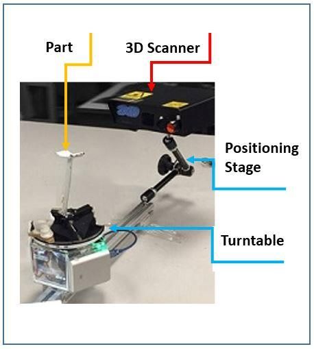
646

 The advantage of proposed method is the registration does not rely on the presence of well
resolved features and the coordinate mappings is practical for guiding the registration of freeform
data with low–overlapping. Promising results can be easily obtained when the optimization of data
registration starts with a good initial pose.

 The major original contributions in this work are:
 i) Integrated measuring system is developed (Fig.1) by incorporating laser scanner into
 hardware mechanism which provides the advantage of extending the scanning range
 with the translation arm and a higher flexibility on complex shape measurement:
 changing the position of the scanner or the camera lens changes the measuring system
 field of view and resolution.
 ii) Proposed calibration method is based on coordinates mapping, that is simple to
 implement and does not require external measuring device.
 iii) The scanner and the turntable of our system are fixed together which can simplify
 transformation calculation by assuming no rotational offset between them.
 iv) Turntable calibration is only using one cylindrical target instead of three tooling balls
 [23], and does not require to move the target to different positions [20] for evaluation.
 v) The coordinates transformation relationship is practical for guiding the registration of
 freeform data in our system.

Reference based technique are proposed for the integrated measuring system and calibrations. A
reference cylinder with known diameter is used as calibration target. For turntable calibration,
several poses of the calibration target are scanned, and the measured data are used to compute the
transformation matrix.
 The results of the experiment have showed that the proposed calibration algorithm is feasible.
It is applied to conduct a part measurement demonstrating the effectiveness and stability of the
system. The rest of the paper is organized as follows. System configurations and measuring principle
of the integrated system are introduced in section 2. Section 3 and Section 4 discussed the proposed
calibration and the details of the experiment. This paper is concluded in Section 5.

2 MECHANICAL CONFIGURATION AND MEASURING PRINCIPLE

2.1 System Configuration
The mechanical hardware of the measuring system is shown in Figure 1. The system is mainly
composed of a laser scanner and a positioning stage and a turntable. The Realscan scanner
manufactured by 3D Digital Corp was chosen with accuracy at 0.15mm level. It is mounted on and
supported by a positioning stage. The positioning stage with flexible mechanism could allow to slide
along a machine base to obtain different standoff between the scanner and the turntable within the
scanner’s measuring range. By rotating around the direction vector ̂( , , ) of rotation axis of the
turntable, various poses of measuring object could be measured. A fixture was designed to hold the
measuring object in the exact centre of turntable. The turntable and the positioning stage is mounted
together on the fixed base.
 Prior to conducting measurement, two degrees of freedom obtained by tilting the scanner head
and adjusting the positioning stage along YZ plane. The position of scanner should be adjusted to
the level that the laser beam is projected parallel to the machine base. So that the -axis of the
scanner, the turntable and the machine base (fixed frame) are aligned always in parallel. It can be
assumed that there is no rotational offset between the machine base and positioning stage, their 3-
axes are aligned always in parallel.

 Computer-Aided Design & Applications, 18(4), 2021, 644-654
 © 2021 CAD Solutions, LLC, http://www.cad-journal.net
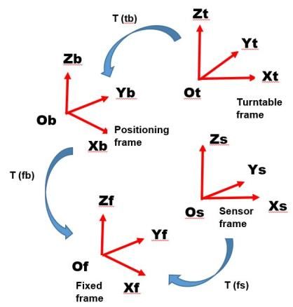
647

 Figure 1: Mechanical structure of the integrated measuring system.

2.2 Coordinate Systems Mapping
Based on the configuration of the integrated system, coordinate systems used in the measuring
process are defined (Figure 1)
 i) the sensor coordinate system (0s,Xs,Ys,Zs)
 ii) the positioning stage coordinate system (0b,Xb,Yb,Zb)
 iii) the turntable coordinate system (0t,Xt,Yt,Zt)
 iv) the machine base coordinate system (0f,Xf,Yf,Zf)

As each coordinate system is defined differently and may not coincide with each other. Therefore,
coordinates of measured points may be differently represented in each coordinate system. The
system needs to be calibrated by determining coordinate transformation between coordinate
systems and an actual space coordinate system in the fixed frame. For a space point P in the system,
the mapping relationship between coordinate f in the machine base frame and in the laser sensor
frame is expressed as follows:

 f = x (2.1)

 f = x
 x
 x (2.2)

Where , and

 are 4 x4 homogenous coordinate transform matrices,
 , denotes transform

relationship between the scanner frame and the machine base frame, is the transformation
between the machine base frame and the positioning stage frame, is the transform relationship
between the positioning stage frame and the turntable frame and denotes transform relationship
between the turntable frame and the laser sensor frame. The acquired data of this integrated
measurement system is unified and assessed in the machine base frame.

2.2.1 Transformation from scanner to Machine base frame
The transformation of coordinates between the laser scanner and the machine base frame is to
determine the transformation matrix from the scanner to the machine base. It is a rigid
transformation with rotation (R) and translation (T) in 3D space.
 The coordinates system of the main base frame is defined as an actual space coordinate system
( , , , ). For acquiring the actual space coordinates, the measured point in the scanner frame
can be calculated by Equation (2.1).

 f = x (2.1)

 Computer-Aided Design & Applications, 18(4), 2021, 644-654
 © 2021 CAD Solutions, LLC, http://www.cad-journal.net
648

which can also be expressed in homogeneous form as

 f = [ ] (2.3)
 0 1
Therefore = +
where and are the rotational matrix and translation vector with respect to rigid transformation
from to . The translation vector is given by the positional offset ( , , ) between the
main frame and the scanner, with respect to the machine base frame. The rotation matrix is given
by the rotational offset between the base frame and the scanner at the time when the measurements
are acquired along by θ .
This can also be written as
 Ø − Ø 0
 Ø Ø 0
 [ ] = [ ] (2.4)
 0 0 1
 1 [ 0 0 0 1 ] 1

2.2.2 Transformation from scanner to turntable
To obtain the complete 3D reconstructed model of measurement, it is necessary to determine the
transformation between the scanner and the turntable coordinate systems to recovery the rotational
motion of acquired data in the turntable frame. As the turntable is not a fixed frame, we unable to
directly determine the transformation matrix from the scanner to the turntable. As thus, we need to
transfer the coordinate system from the scanner frame to the fixed frame first and then recovery
the coordinate system of the turntable frame from the fixed frame. Based on equations (2.1) and
(2.2), we can get:

 f = x
 x x

 (2.5)

 f = x Ps = x

 x
 x (2.6)
For simplification, the origin of positioning stage frame as the actual space coordinate, then we get
 = x = x
 x (2.7)
 Then =
 x ,

 = -1 x (2.8)
 Therefore,
 = x
 (2.9)

We assume the direction axis of the turntable and the z axis of the positioning stage is parallel
aligned so that there is only positional offset, no rotational offset. The translation vector (-Xbt,-Ybt,-
Zbt ) is the relative position of the origin of positioning stage with respect to the centre of the
turntable, Ø is the rotational offset about the Z-axis between the turntable and the positioning frame
at the time when the measurements are acquired, i.e rotation angle of the turntable.

 Transformation Rotational translation
 matrix vector

 along Zt Xbt,Ybt,Zbt Ø − Ø 0
 by Øt
 [ ] = [ Ø Ø 0 ] [ ] (2.10)
 0 0 1
 1 0 0 0 1 1

 No Xbs,Ybs,Zbs 1 0 0
 rotational 0 1 0
 [ ] = [ ] [ ] (2.11)
 offset 0 0 1
 1 0 0 0 1 1

In homogeneous form,

 Computer-Aided Design & Applications, 18(4), 2021, 644-654
 © 2021 CAD Solutions, LLC, http://www.cad-journal.net
649
cos(− Ø ) −sin (−Ø ) 0 0 1 0 0 −
sin (−Ø ) cos (−Ø ) 0 0 0 1 0 −
[ ] =[ ][ ] [ ] (2.12)
0 0 1 0 0 0 1 −
1 0 0 0 1 0 0 0 1 1
Therefore, we can calculate the coordinates (Xt,Yt,Zt) on the measured point with respect to the
turntable frame by equation (2.9), that is recovery of rotation motion.
3 CYLINDRICAL BASED CALIBRATION
3.1 Locate the Rotation Axis and Centre
In order to calibrate the turntable, the rotation axis and the centre of the turntable should first be
determined with respect to the laser scanner. In this work, this is done by measuring a reference
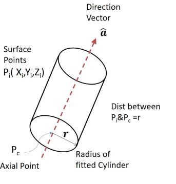
cylinder mounted on the turntable. As shown in Fig.2 for a cylinder defined by a point ⃗ ( , , ) on
its axis, a direction vector along its axis ̂ ( , , ) and radius r , estimate of these parameters may
be obtained by minimising the distance function between centre point of cylinder and its normal
surface point.
Figure 2: Location of coordinate system of turntable.
Firstly, the cylinder is fixed in the centre of the turntable, and surface points are acquired and
expressed by ⃗ ( , , ), = 1, ⋯ , in the scanner coordinate system. We repeated the measurement
at different positions by rotating the turntable. From acquired points, a cylinder with an arbitrary
axis ( ⃗ , ̂) is approximated by calibrating the radius error of cylinder. According to the geometrical
relationship, the distance from the centre point ( ⃗ ) on the axis of fitted cylinder to its surface
points is the radius (r), ‖( ⃗ − ⃗ ) − ( ⃗ − ⃗ ) ∙ ̂ ̂‖ = . Then the direction vector and the center position
of cylinder ̂ ( , , ) is calculated by a least square method.
In cartesian coordinate form:
2
{( − ) − [( − ) + ( − ) + ( − ) ] } + {( − ) − [( − ) + ( − ) + ( −
2 2
) ] } + {( − ) − [( − ) + ( − ) + ( − ) ] } − 2 = 0 (3.1)
Simplify using 2+ 2 = 1, and with fitting errors, , then the direction vector ( ̂) and axial
+ 2
points , ,
⃗ ( )on the point on the centre axis of the fitted cylinder are obtained.
The direction vector of the rotation axis ̂( , , ) is obtained. If the centre point of the turntable
lies along the rotation axis, then the origin of the turntable after the transformation to an arbitrary
datum plane can be expressed in matrix form as:
⃗ ( , , ) = ⃗ ( , , ) +T1 (3.2)
where T1 is the positional transformation .
Computer-Aided Design & Applications, 18(4), 2021, 644-654
© 2021 CAD Solutions, LLC, http://www.cad-journal.net650 3.2 Turntable Calibration Here, we assume that the position of the origin of the turntable is located exactly at the center of actual space coordinates, and the rotational axis of the turntable coincides with the z-axis of actual space coordinates. In this work, turntable calibration can be understood as the process to determine the discrepancies between the measured and the ground true of the rotation angle. The main steps include first to recover the angles between two different poses of the turntable from the estimated image invariants. Second determine the rotation error by measuring the differences between actual and measured angle. The procedure is by rotating the turntable in different angles, measured data of the reference object before and after the rotation is obtained. We calculated the actual space coordinates (Pt) of each acquired point (Ps) of the cylinder by substituting into equation (2.11) and (2.12), where Ps is acquired point from the scanner and Pt is the point transferred in the turntable frame. Then the measured angle of the rotation can be calculated by Pi+1 = Ra x Pi (3.3) Pi = measured points of the reference object before the rotation of turntable Pi+1 = measured points of the reference object after the rotation of turntable Ø − Ø 0 Ra = [ Ø Ø 0] 0 0 1 ∅ = the angle of the turntable rotation. By comparing the differences between the measured value and the ground truth, the accuracy of the turntable is determined. Repeating the above procedure at least three times, several sets of Pi and Pi+1 can be obtained and then Ra can be solved with a nonlinear least square method, i.e, Leveberrg-Marquard algorithm. Then a new rotation matrix can be calculated to offset the found error. 4 EXPERIMENTS To validate proposed calibration method, the developed system was applied for experiments include: (1) Calibration experiment is performed to illustrate the robustness of method and standard cylinder is measured to analyze the calibration error. (2) Measurement of blade part is completed and proves the performance of the method. 4.1 Calibration Error Calibration experiments were performed to calibrate the turntable accuracy of developed system. For checking the rotational error of turntable, a reference cylinder is adopted and placed on the turntable as shown in fig 3. In this experiment, the procedure is based on digitizing the reference cylinder with a rotation angle of 60◦ per step of the turntable, the total number of scanned data was six. Each digitized cylinder was reconstructed and recovered their coordinates in the turntable frame as shown in Fig 3. Then measured angle of the rotation between two different poses from the fitted cylinder are estimated by equation (2.10). To analyze the results, the measured angle (θM ) was compared to the ground truth respectively. Table I lists the rotation error of the turntable on the average of ten trials. The maximum deviation below 0.3 ° and the average absolute deviation is 0.15 °. This verifies the accuracy of the turntable from one perspective. Then a new rotation matrix can be determined to offset the found error with equation (2.10) and acquired data by the nonlinear least square method. The new matrix can be used in the subsequent multi-view reconstruction. Computer-Aided Design & Applications, 18(4), 2021, 644-654 © 2021 CAD Solutions, LLC, http://www.cad-journal.net
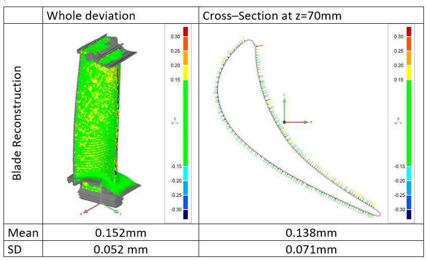
651

 Figure 3: Turntable calibration.

 Pose 1-2(i=1) 2-3 (i=2) 3-4(i=3) 4-5(i=4) 5-6(i=5)
 θM

 60.15 60.1 60.11 60.3 60.1
 60 60 60 60 60
 Abs Dev 0.15 0.1 0.11 0.3 0.1

 Table 1: Rotation error of the turntable.

4.2 Test on Blade Part
The purpose of this experiment is to verify the effectiveness of the developed system with practical
application- reconstruction of complex shape. We conducted experiments on a blade which has 42.3L
x29.3W x140H mm with various freeform and twist surfaces. After finishing the turntable calibration
process, the integrated measurement system is applied to scan the blade part. During the
measurement, the blade is fixed by a fixture, which is mounted on the turntable. Six partial views
have been acquired from the part. Finally, the point clouds can be aligned into the common
coordinate system by equation (2.11) and (2.12) to form a complete 3D shape of the blade, which
is illustrated in fig 4. The measurement results have been obtained on the average of ten trials. We
evaluated the mean-square-error (MSE) and standard deviation (SD) to assess the reconstruction
quality. The reconstructed model was also compared with the CAD which obtained from the CMM.
The error is shown by color map in fig 4. It can be seen that the reconstructed error MSE was
0.152mm in the whole deviation and 0.138mm in cross section at h=70mm. Since the manufacturer-
given accuracy of the scanner is 0.15 mm. The test results of the blade reconstruction demonstrated
a good effectiveness of developed system. This verifies the measured result could be unified in the
turntable frame. The error over 0.15mm in is partly attribute to reflectivity of the blade surface.

 Figure 4: Measurement of Blade part.

 Computer-Aided Design & Applications, 18(4), 2021, 644-654
 © 2021 CAD Solutions, LLC, http://www.cad-journal.net
652

5 CONCLUSIONS
This paper presents an integrated system for complex shape reconstruction where a laser scanner
and turntable are combined to perform measurement of part. In order to calibrate the rigid
transformation between coordinate systems of scanner and turntable, a calibration method is
proposed by using cylindrical target and relating any two views in a turntable sequence. This
approach can recover the rotation angles precisely without external measurement device.
 After calibration, measuring accuracy of the integrated system is evaluated and MSE error of
0.152mm was detected. The experimental results clearly demonstrated that the robust of proposed
method in the calibration of turntable and the integrated system is feasible and well suited for the
measurement. The application of blade measurement is also performed to demonstrate its
effectiveness in 3d metrology. Finally, we would like to point that the integrated measurement
system proposed is relatively low-cost, it is well suited for application of product quality control,
reverse engineering.

ACKNOWLEDGMENT
This work is supported in part by the National Basic Research Program of China-973 (Grant No.
2013CB035805).

Juliana M.Y. Tam, http://orcid.org/0000-0002-8581-5203
Kai M. Yu, https://orcid.org/0000-0002-5187-9006

REFERENCES
[1] Mohaghegh, K.; Sadeghi, M.H.; Abdullah, A.; Boutorabi, R.: Improvement of reverse-
 engineered turbine blades using construction geometry, The International Journal of Advanced
 Manufacturing Technology, 49 (5-8), July 2010, 675-687. https://doi.org/10.1007/s00170-
 009-2409-9
[2] Makem, J.E.; Ou, H.; Armstrong, C.G.: A virtual inspection framework for precision
 manufacturing of aerofoil components, Computer-Aided Design, 44(9), Sep. 2012, 858-874.
 https://doi.org/10.1016/j.cad.2012.04.002
[3] He, W.; Li, Z.; Guo, Y.; Cheng, X.; Zhong, K.; Shi, Y.: A robust and accurate automated
 registration method for turbine blade precision metrology, The International Journal of
 Advanced Manufacturing Technology, 97(9-12), 2018, 3711-3721.
 https://doi.org/10.1007/s00170-018-2173-9
[4] Mehrad, V.; Xue, D.; Gu, P.: Robust localization to align measured points on the manufactured
 surface with design surface for freeform surface inspection, Computer-Aided Design, 53, 2014,
 90-103. https://doi.org/10.1016/j.cad.2014.04.003
[5] Hsu, T.-H.; Lai, J.-Y.; Ueng, W.-D.; Hwang, J.-Z.: An iterative coordinate setup algorithm for
 airfoil blades inspection, The International Journal of Advanced Manufacturing Technology,
 26(7), 2005, 797-807. https://doi.org/10.1007/s00170-003-2040-0
[6] Barbero, B.R.; Ureta, E.S.: Comparative study of different digitization techniques and their
 accuracy, Computer-Aided Design, 43(2), Feb. 2011, 188-206.
 https://doi.org/10.1016/j.cad.2010.11.005
[7] Savio, E.; De Chiffre, L.; Schmitt R.: Metrology of freeform shaped parts, CIRP Annals -
 Manufacturing Technology, 56(2), 207, 810-835. https://doi.org/10.1016/j.cirp.2007.10.008
[8] Herráez, J.; Martínez, J.C.; Coll, E.; Martín, M.T.; Rodríguez, J.: 3D modeling by means of
 videogrammetry and laser scanners for reverse engineering, Measurement, 87, June 2016,
 216-227. https://doi.org/10.1016/j.measurement.2016.03.005
[9] Barone, S.; Paoli, A.; Razionale, A.V.: Shape measurement by a multi-view methodology based
 on the remote tracking of a 3D optical scanner, Optics and Lasers in Engineering, 50(3), March
 2012, 380-390. https://doi.org/10.1016/j.optlaseng.2011.10.019

 Computer-Aided Design & Applications, 18(4), 2021, 644-654
 © 2021 CAD Solutions, LLC, http://www.cad-journal.net
653

[10] Yilmaz, O.; Gindy, N.; Gao, J.: A repair and overhaul methodology for aeroengine components,
 Robotics and Computer-Integrated Manufacturing, 26(2), April 2010, 190-201.
 https://doi.org/10.1016/j.rcim.2009.07.001
[11] Tam, J.M.Y.; Yu, K.M.; Sun, R.L.: Integrated computer-aided verification of turbine blade,
 Computer-Aided Design and Applications, 12(5), 2015, 589-600.
 https://doi.org/10.1080/16864360.2015.1014738
[12] Katz, R.; Srivatsan, V.; Patil, L.: Closed-loop machining cell for turbine blades, The
 International Journal of Advanced Manufacturing Technology, 55(9-12), 2011, 869-881.
 https://doi.org/10.1007/s00170-010-3138-9
[13] He, W.; Zhong, K.; Li, Z.; Meng, X.; Cheng, X. Liu, X.; Shi, Y.: Accurate calibration method for
 blade 3D shape metrology system integrated by fringe projection profilometry and conoscopic
 holography, Optics and Lasers in Engineering, 110, Nov. 2018, 253-261.
 https://doi.org/10.1016/j.optlaseng.2018.06.012
[14] Lu, K.; Wang, W.: A multi-sensor approach for rapid and precise digitization of free-form
 surface in reverse engineering, The International Journal of Advanced Manufacturing
 Technology, 79(9-12), 2015, 1983-1994. https://doi.org/10.1007/s00170-015-6960-2
[15] Chane, C.S.; Schütze, R.; Boochs, F.; Marzani, F.S.: Registration of arbitrary multi-view 3D
 acquisitions, Computers in Industry, 64(9), Dec. 2013, 1082-1089.
 https://doi.org/10.1016/j.compind.2013.03.017
[16] Bellocchio, F.; Ferrari, S.: 3D Scanner, State of the Art, In Malik, A.S.; Choi, T.S.; Nisar, H.
 (Eds.), Depth Map and 3D Imaging Applications: Algorithms and Technologies, 2012, 451-470.
 Hershey, PA: IGI Global. https://www.igi-global.com/gateway/chapter/60280
[17] Zhang, H.; Wong, K.K.: Self-calibration of turntable sequences from silhouettes, IEEE Trans
 Pattern Analysis and Machine Intelligence, 31(1), Jan. 2009, 5-14.
 https://doi.org/10.1109/TPAMI.2008.56
[18] Chen, P.; Dai, M.; Chen, K.; Zhang, Z.: Rotation axis calibration of a turntable using
 constrained global optimization, Optik, 125(17), Sep. 2014, 4831-4836.
 https://doi.org/10.1016/j.ijleo.2014.04.047
[19] Lin, A.C.; Hui-Chin, C.: Automatic 3D measuring system for optical scanning of axial fan blades,
 The International Journal of Advanced Manufacturing Technology, 57(5), 2011, 701-717.
 https://doi.org/10.1007/s00170-011-3329-z
[20] Pang, X.; Lau, R.W.H.; Song, Z.; Li, Y. He, S.: A Tool-Free Calibration Method for Turntable-
 Based 3D Scanning Systems, IEEE Computer Graphics and Applications, 36(1), Jan.-Feb. 2016,
 52-61. https://doi.org/10.1109/MCG.2014.83
[21] Huang, Y.; Qian, X.; Chen, S.: Multi-sensor calibration through iterative registration and fusion,
 Computer-Aided Design, 41(4), April 2009, 240-255.
 https://doi.org/10.1016/j.cad.2008.10.003
[22] Zhang, P.C.; Xu, D.; Zou, W.; Wu, B.L.: Positioning Cylindrical Target Based on Three-
 Microscope Vision System, IEEE/ASME Transactions on Mechatronics, 19(5), Oct. 2014, 1612-
 1624. https://doi.org/10.1109/TMECH.2013.2290742
[23] Yun, D.; Kim, S.; Heo, H.; Ko, K.H.: Automated registration of multi-view point clouds using
 sphere targets, Advanced Engineering Informatics, 29(4), Oct. 2015, 930-939.
 https://doi.org/10.1016/j.aei.2015.09.008
[24] Liu, Y.; Rodrigues, M.A.: Geometrical Analysis of Two Sets of 3D Correspondence Data Patterns
 for the Registration of Free-Form Shapes, Journal of Intelligent and Robotic Systems, 33(4),
 2002, 409-436. https://doi.org/10.1023/A:1015500622943
[25] Zhao, Y.; Wang, Z.; Fu, L.; Qu, X.; Zhang, H.; Liu, C.: A new method for registration of
 heterogeneous sensors in a dimensional measurement system, Measurement Science and
 Technology, 28(10), 2017, 105012. https://iopscience.iop.org/article/10.1088/1361-
 6501/aa80b7
[26] Besl, P.J.; McKay, N.D.: A method for registration of 3D shapes, IEEE Transactions on Pattern
 Analysis and Machine Intelligence, 14(2), Feb. 1992, 239–256.
 https://doi.org/10.1109/34.121791

 Computer-Aided Design & Applications, 18(4), 2021, 644-654
 © 2021 CAD Solutions, LLC, http://www.cad-journal.net
654

[27] Zheng, J.; Li, Z.; Chen, X.: Worn area modeling for automating the repair of turbine blades,
 International Journal of Advanced Manufacturing Technology, 29, 2006, 1062-1067.
 https://doi.org/10.1007/s00170-003-1990-6
[28] Zhu, L.; Barhak, J.; Srivatsan, V.; Katz, R.: Efficient registration for precision inspection of
 free-form surfaces, The International Journal of Advanced Manufacturing Technology, 32,
 2007, 505-515. https://doi.org/10.1007/s00170-005-0370-9
[29] Bo, L.J.; Liu, F.; Zhan, S.: An accurate and practical means for the automatic registration of
 multiple 3D scanning data, 2014 4th IEEE International Conference on Information Science
 and Technology, Shenzhen, 2014, 619-622. https://doi.org/10.1109/ICIST.2014.6920554

 Computer-Aided Design & Applications, 18(4), 2021, 644-654
 © 2021 CAD Solutions, LLC, http://www.cad-journal.net
You can also read