KiboCUBE Academy - UNOOSA
←
→
Page content transcription
If your browser does not render page correctly, please read the page content below
Day #1 01.14 21:00~23:00 (JST)

KiboCUBE Academy
                                      Lecture 1-2

                    Introduction to
                 CubeSat Technologies
                                   Tohoku University
                        Department of Aerospace Engineering
                   Associate Professor Dr. –Ing. Toshinori Kuwahara
     This lecture is NOT specifically about KiboCUBE and covers GENERAL engineering topics of
                           space development and utilization for CubeSats.
        The specific information and requirements for applying to KiboCUBE can be found at:
                  https://www.unoosa.org/oosa/en/ourwork/psa/hsti/kibocube.html
Contents

                   1.   Introduction to Space Systems
                   2.   Introduction to CubeSat Systems
                   3.   Definition of Satellite Subsystems
                   4.   CubeSat Payload Systems
                   5.   Launch Environment
                   6.   Safety Design
                   7.   Mission Assurance
                   8.   Conclusion

January 14, 2021                              KiboCUBE Academy   2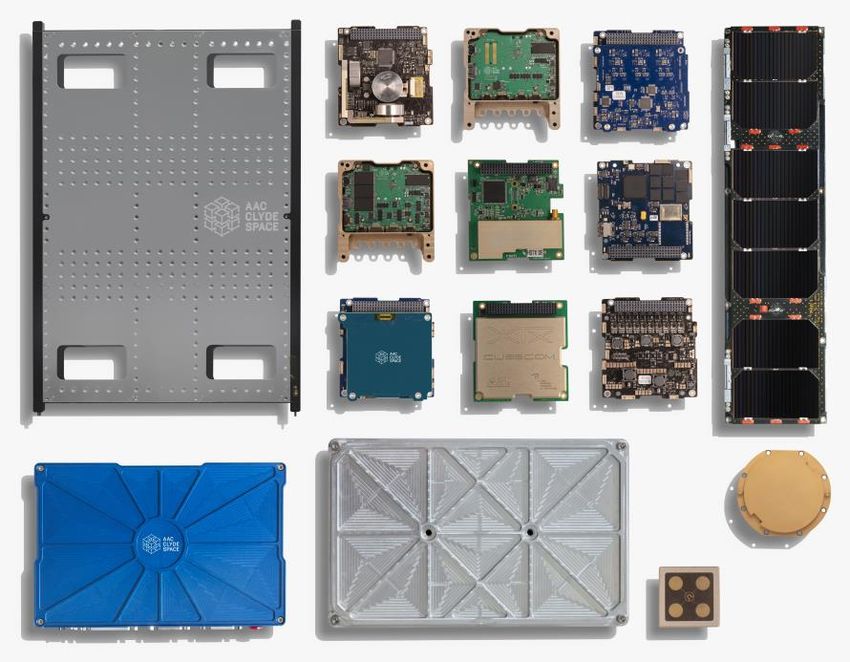
1. Introduction to Space
         Systems

January 14, 2021     KiboCUBE Academy   3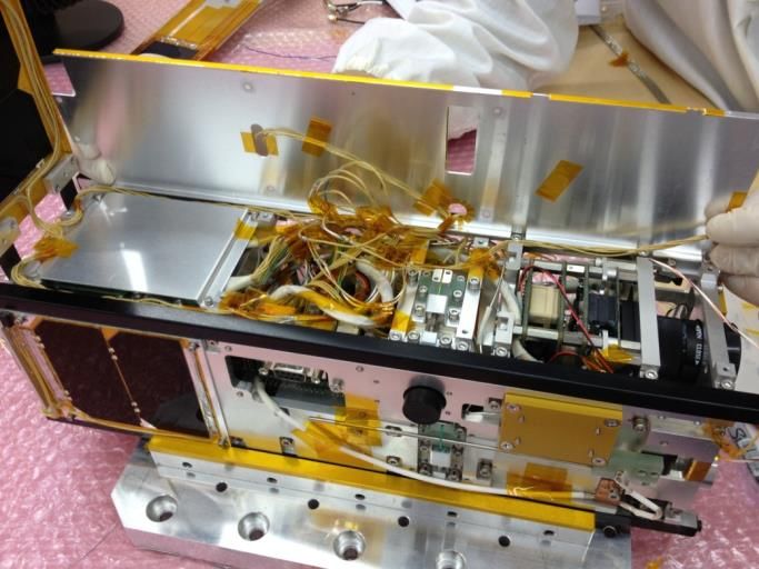
1. Introduction to Space Technologies and Utilization
Satellite Orbits
There are many different types of satellite orbits.
The most appropriate orbit for the mission needs to be selected.
Mission needs to be designed according to the available satellite orbits.
zi
SSO: Sun Synchronous Orbit ISS Orbit
(Polar Orbit) ~400km
i = 51.6°
yi
GEO: Geosynchronous Orbit
LEO: Low Earth Orbit ~36,000km
xi
January 14, 2021 KiboCUBE Academy 4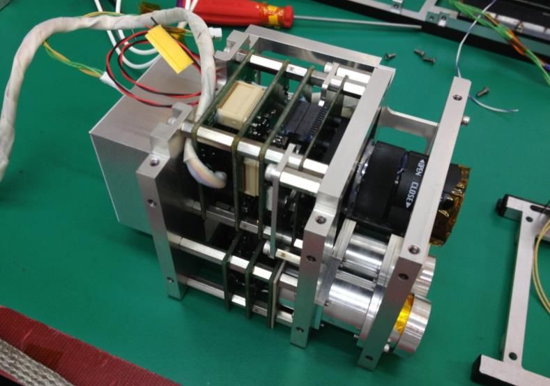
1. Introduction to Space Technologies and Utilization
Satellite Operation / Ground Station
Satellites rotate around the Earth, about 16 times per day in Satellite
the orbit of International Space Station (ISS).
Earth also rotates once per day.
Relative velocity between the ground station and the satellite
is on the order of about 7.7 km/s.
Satellite operator has a limited amount of time for
communicating with the satellites (about 10 minutes or less
per contact, several times a day).
Satellite operator sends commands to satellites from the
ground station and receives telemetry data from them.
For satellite operation, following aspects must be considered:
Satellite Orbit and Mission Lifetime
Communication System
Ground Station
Link Budget Design
Operational Phase
Regulations
Ground Station
January 14, 2021 KiboCUBE Academy 5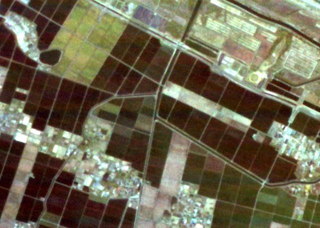
1. Introduction to Space Technologies and Utilization
Characteristics of Satellite Utilization
Satellites orbiting in high-inclination orbits can cover a large portion of geographical
area on Earth. This feature of global accessibility can be utilized for:
Earth observation: periodic, frequent observation of ground area under the satellite orbit.
Communication: can have communication contact with ground stations in the visible area.
Environmental measurement: can measure space environment, such as magnetic fields,
radiations, etc.
Higher orbit can have a wider field of view, and lower orbit can facilitate higher ground
resolutions of Earth observation.
Satellites are basically continuously “falling”
toward the Earth. This free-fall micro-gravity
environment can be utilized for experiments of
material science, bioscience, medicine, etc.
Space also provides unique environments such
as vacuum, high radiation, strong ultraviolet
light, cold and hot temperature, and existence
of atomic oxygen and plasma, etc. Spheresoft
January 14, 2021 KiboCUBE Academy 6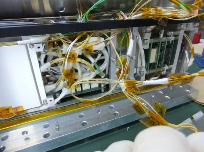
2. Introduction to CubeSat
         Systems

January 14, 2021     KiboCUBE Academy   7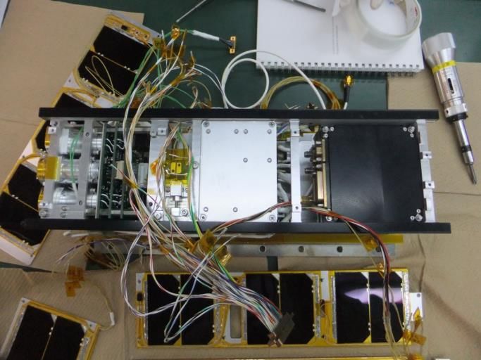
2. Introduction to CubeSat Systems
CubeSat Standards
A 1U CubeSat is a 10 cm cube with a mass of up to 1.33kg.
Some standards are available:
CubeSat Design Specification rev.13
- California Polytechnic State University (2014/2/20)
(https://www.cubesat.org/) © University of Tokyo
CubeSat System Interface Definition version 1.0
- UNISEC Europe (2017/8/24)
(http://unisec-europe.eu/wordpress/wp-content/uploads/CubeSat- 100 mm
Subsystem-Interface-Standard-V2.0.pdf)
100 mm
JEM* Payload Accommodation Handbook Vol.8 D (Japanese)
- JAXA (2020/5/25)
(https://iss.jaxa.jp/kibouser/provide/j-ssod/#sw-library)
(https://iss.jaxa.jp/kibouser/library/item/jx-espc_8d.pdf )
113.5 mm
JEM Payload Accommodation Handbook Vol.8 C (English)
- JAXA (2018/11)
(https://iss.jaxa.jp/kibouser/library/item/jx-espc_8c_en.pdf)
rev. D (English) is to be released soon.
* Japanese Experiment Module (JEM) = Kibo
January 14, 2021 KiboCUBE Academy 8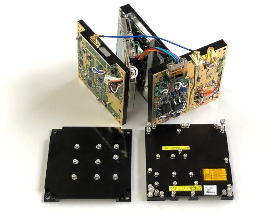
2. Introduction to CubeSat Systems
 Kibo Release Opportunities

                                                                                       1U x 1U x 1U
                                                                                       1U x 1U x 1.5U
                                                                                       1U x 1U x 2U
                                                                                       1U x 1U x 3U
                                                                                       1U x 1U x 4U
                                                                                       1U x 1U x 5U
                                                                                       1U x 1U x 6U
                                                                                       1U x 2U x 3U

                   Reference: JEM Payload Accommodation Handbook Vol. 8 D (Japanese)
                   https://iss.jaxa.jp/kibouser/library/item/jx-espc_8d.pdf
January 14, 2021                              KiboCUBE Academy                                          9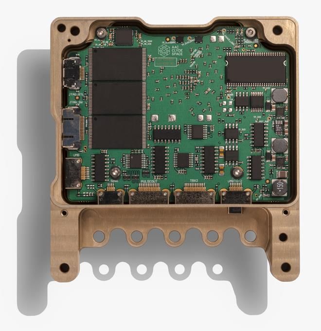
2. Introduction to CubeSat Systems
1U CubeSat
Best platform to learn essential engineering skills and technologies for satellite
development and operation.
A 1U CubeSat is the simplest implementation and larger formats can be selected
depending on the technology level and mission requirements.
Smaller format is mainly for fundamental functionalities and missions which
require larger sensors, attitude control, and large amount of data transfer require
larger formats.
© Kyutech
January 14, 2021 KiboCUBE Academy 102. Introduction to CubeSat Systems
CubeSat Components
Some CubeSat components are commercially available for quick access to space.
© AAC Clyde Space
January 14, 2021 KiboCUBE Academy 113. Definition of Satellite
Subsystems
January 14, 2021 KiboCUBE Academy 123. Definition of Satellite Subsystems
Satellite Subsystems
A satellite system consists of several subsystems. Typical categorization is as follows:
Power Control System
Orbit Control System Communication System
(Advanced)
Payload
Attitude Control System System Command and Data Handling System
Thermal Control System Structure and Mechanism System
+ Harness System
January 14, 2021 KiboCUBE Academy 133. Definition of Satellite Subsystems
Power Control System
Power control systems manage power generation by solar panels, storage into
secondary batteries, and distribution to the satellite components.
Power control systems shall be highly reliable, as compared to other on-board
components.
Size of solar cells and capacity of the battery shall be determined based on the power
consumption requirements of the satellite mission.
Power Control System Block Diagram
Power
Solar
Control
Cells Satellite
Satellite
Unit Satellite
Components
Components
Voltage Components
Sunshine
Converters
Eclipse
Battery
Solar Array and Battery ©GomSpace Electrical Power Control System Integrated Power management and
© AAC Clyde Space communication system © Addnics corp.
January 14, 2021 KiboCUBE Academy 143. Definition of Satellite Subsystems
Power Control System
Attitude
Example of 2U CubeSat
sensors
“RAIKO”
sun sensors, magnetometers, GPS receiver
actuators 3-axis magnetic coils
Power
solar cells ZTJ Photovoltaic Cell (>29.5% efficienty)
2 series x 6 parallels (no paddle open)
2 series x 10 parallels (paddle opened)
batteries 8-cell NiMH (total 750mAH, 9.6V)
power 3.19 W (avg. in sunshine, no paddle open)
generation 4.70 W (avg. in sunshine, paddle opened)
2U CubeSat RAIKO
power 4.90 W (communication mode)
comsumption 1.05 W (standby mode)
January 14, 2021 KiboCUBE Academy 153. Definition of Satellite Subsystems Communication System – Transmitter/Receiver As the satellite operates remotely in space, information exchange through communication is indispensable to make the mission of the satellite meaningful. The communication throughput (amount of data), especially for the down-link, determines/limits the entire performance of the satellite system itself. For high-speed communication, higher electrical power is required, and the temperature of the transmitter increases. (Typically a ground contact lasts about 10 minutes or less.) Receiver shall be ideally powered on all the time so that the satellite doesn’t miss any commands sent from the ground station. Transmitter can be turned on and off according to the ground contact schedule. The amount of mission data down-link can be increased by using more than one ground station if available. Collaborative satellite operation is very useful. CubeSat S-band RF Transmitter and Receiver, X-band Transmitter, and inside of the X-band Transmitter (from left to right) © Addnics corp. January 14, 2021 KiboCUBE Academy 16
3. Definition of Satellite Subsystems
 Communication System – Antenna

                   Low Frequency / Long Wavelength                  High frequency / Short Wavelength

        Antenna                                               Antenna

                     Yagi-Antenna for VHF-band                        Dish-Antenna for S-Band
January 14, 2021                                 KiboCUBE Academy                                       17
3. Definition of Satellite Subsystems
Command and Data Handling System
Command and Data Handling System, often denoted as C&DH, manages data handling,
components commanding/monitoring, data storage, signal processing (for
communication), and error handling inside the satellite.
Certain levels of autonomous functions need to be implemented in C&DH so that
satellites can survive in the space environment.
A high level of reliability is required for the C&DH computers. When errors occur, due
to e.g. radiation effects, the power control system shall power cycle (power off and on)
the computer either autonomously or by telecommand from the ground station.
PIC Computer High-end CubeSat On-board Computers © AAC Clyde Space
January 14, 2021 KiboCUBE Academy 183. Definition of Satellite Subsystems
Structure and Mechanism System
Structure System
Satellite structure system is the main interface with the
launch vehicle. In case of CubeSats, the rails are the contact
points between the satellite and the pod.
The outer dimensions, surface area, and surface treatment
of the rails and outer envelope of the entire satellite are
specified.
Structure system shall withstand launch environment, such 1U CubeSat Structure
as vibration, static acceleration, shock, (acoustic, air
venting), etc.
Mechanical System
Mechanical system includes separation switches, deployable
antennas, deployable solar panels, shutters, booms, and any
other mechanically moving elements on the satellite.
Mechanical system shall be safely stowed during the launch
to ensure the secure deployment of the CubeSat from the
pod. Deployable Solar Panel for 3U CubeSat
© AAC Clyde Space
January 14, 2021 KiboCUBE Academy 193. Definition of Satellite Subsystems
Thermal Control System
Thermal control of a satellite can be
achieved in two different ways:
Passive control
Active control
As active control needs electrical
power (heaters/coolers) in general,
passive control is the usual thermal © JAXA
control concept of CubeSats. 1U CubeSat FREEDOM
Passive thermal control utilizes Nakashimada Engineering Works, Ltd.
different surface materials with Example of 1U CubeSat “FREEDOM”
different thermo-optical
characteristics in order to adjust Aluminum
heat exchange between the deep
space and the Earth.
Aluminum surface contributes to
warming up the temperature.
Kapton surface contributes to
cooling down the thermal condition.
Rail
January 14, 2021 KiboCUBE Academy 203. Definition of Satellite Subsystems
Attitude Control System
Attitude control capability is required depending on the
mission operation of the satellite, such as:
Pointing observation instruments toward the target
Pointing high-gain antenna toward the ground station for
high-speed communication
Orienting solar panels toward the sun for larger power
generation
For the attitude control, attitude determination is also
necessary beforehand, therefore attitude determination
sensors and attitude control actuators are required.
Type of attitude control
Passive control
Active control
Attitude control modes
Detumbling control (after the separation from the launch
vehicle or release from the ISS).
Pointing control: inertial, nadir, target, velocity direction, etc.
January 14, 2021 KiboCUBE Academy 213. Definition of Satellite Subsystems
Attitude Control System – Detumbling Control
Detumbling Control
Satellites can experience high rotational rate after the Rotation
separation from the launch vehicle or deployment from the
ISS.
In general, satellites in high-speed rotation cannot
communicate with the ground station properly.
Satellites shall be able to detumble and reduce rotational
speed down to about several degrees per second.
Type of detumbling control Earth Magnetic Field
Active control
Generate magnetic moment by means of magnetic torquers
to interact with Earth magnetic field to actively slow down the
rotational rate.
Passive
Utilize permanent magnets and magnetic hysteresis dumpers
to passively slow down the rotational rate. Magnetic Torquers
(Electrical Coil)
January 14, 2021 KiboCUBE Academy 223. Definition of Satellite Subsystems
Attitude Control System – Gravity Gradient Control
Gravity Gradient Control (passive control) Centrifugal force
Satellites with long shapes and spread mass
Τg = 3 o 3 I o 3
distribution experience gravity gradient R3
torque such that the longitudinal direction Gravity Gradient Torque
points toward the Earth.
Cameras, antennas, sensors can be pointed
toward the Earth without additional Boom
electrical power for the attitude control.
Pointing accuracy is relatively low. o3
Can be combined with active attitude control Gravity
with some attitude control actuators such as
magnetic torquers and reaction wheels.
Orbit
Normal
: gravitational constant, R : orbit radious
o 3 : observation vector (Z - axis)
January 14, 2021 KiboCUBE Academy 233. Definition of Satellite Subsystems Attitude Control System – 3-axis Control Active 3-axis Control Attitude control actuators such as magnetic torquers and reaction wheels are used for active 3-axis control. Reaction wheels can realize agile and stable attitude control. Disturbance torques acting on the satellite gradually accumulate as angular momentum stored in the reaction wheels. Reaction wheels cannot be operated for a long time without desaturation using magnetic torquers. Satellite attitude shall be determined precisely by means of a combination of attitude determination sensors. January 14, 2021 KiboCUBE Academy 24
3. Definition of Satellite Subsystems
Payload System
Payload system is the on-board components
dedicated to the satellite’s missions.
Good practice is to define clear interfaces
(mechanical and electrical) with the bus
system.
Example of 3U CubeSat “S-CUBE”
1U is assigned for the payload instruments
10 cm
2U is assigned for satellite bus system
Bus System Section
Payload Section
3U CubeSat S-CUBE © Chiba Institute of Technology / Tohoku University
January 14, 2021 KiboCUBE Academy 253. Definition of Satellite Subsystems
Harness System
Harness system is not negligible affecting the handling ability during integration.
3U CubeSat S-CUBE © Chiba Institute of Technology / Tohoku University
January 14, 2021 KiboCUBE Academy 264. CubeSat Payload Systems January 14, 2021 KiboCUBE Academy 27
4. CubeSat Payload Systems
Types of Payload Systems
Each CubeSat has its own missions. The larger the CubeSat is, the more payload
instruments can be carried and the more advanced missions can be conducted.
Examples of CubeSat payload instruments.
Observation cameras (Earth, Planetary, Astronomy, etc.)
In-situ space environment measurement sensors
Meteor measurement sensors
Communication instruments
Engineering demonstrations
Deployment mechanisms
Advanced technologies (new sensors, electrodynamic tether, etc.)
Some examples are illustrated in the following slides.
January 14, 2021 KiboCUBE Academy 284. CubeSat Payload Systems
Earth Observation Camera System
Example of 2U CubeSat “RAIKO”
Earth Observation Camera System
New sensor: Star Tracker
2U CubeSat RAIKO
January 14, 2021 KiboCUBE Academy 294. CubeSat Payload Systems
Meteor Observation
Example of 3U CubeSat “S-CUBE”
Meteor Observation Camera System
Gravity Gradient Boom
Deployable Solar Panels
Gravity gradient boom was used to point the
meteor observation camera toward the Earth’s
atmosphere to detect incandescent meteors as
they enter the atmosphere.
3U CubeSat S-CUBE © Chiba Institute of Technology / Tohoku University
January 14, 2021 KiboCUBE Academy 304. CubeSat Payload Systems
Signal Measurement Instrument
Example of 3U CubeSat
AIS (Automatic Identification System) signal
receiver
Deployable directional antenna
3-axis attitude control was utilized to point the
antenna toward the Earth to detect AIS signals sent
from ships to track the positions of the ships with a
higher geographical resolution.
Hight: 33mm
80mm 80mm
January 14, 2021 KiboCUBE Academy 314. CubeSat Payload Systems
Deployment Mechanism – De-orbit Sail
Example of 1U CubeSat “FREEDOM”
De-orbit sail for fast de-orbiting and re-entry into
Earth atmosphere from ISS orbit.
No communication system, and solar cells. “FREEDOM”
FREEDOM demonstrated on-orbit deployment of
the thin-film based de-orbit sail, which can be
utilized for space debris mitigation and prevention
using atmospheric drag.
The successfully demonstrated device is now
available for CubeSats and micro-satellites.
1U CubeSat FREEDOM © Nakashimada Engineering Works, Ltd. / Tohoku University
January 14, 2021 KiboCUBE Academy 324. CubeSat Payload Systems
Engineering Demonstration – Electrodynamic Tether
Example of 3U CubeSat “ALE-EDT”
Electro-dynamic tether for de-orbiting and re-entry into Earth atmosphere.
3-axis attitude control is used to control the satellite attitude during the extension of the
electrodynamic tether. The device will be useful for space debris mitigation and
prevention in higher altitude orbits, as it can operate independent of atmospheric drag.
© ALE Co., Ltd.
January 14, 2021 KiboCUBE Academy 335. Launch Environment January 14, 2021 KiboCUBE Academy 34
5. Launch Environment
Launch Conditions of KiboCUBE’s Launch Vehicles
Random vibration condition
Random vibration conditions of launch vehicles
Quasi-static acceleration condition Shock condition
HTV-X: 6.0 [g] N/A
SpaceX Dragon: 9.0 [g]
Orbital Cygnus: 9.0 [g]
Reference: JEM Payload Accommodation Handbook Vol. 8 D (Japanese)
https://iss.jaxa.jp/kibouser/library/item/jx-espc_8d.pdf
January 14, 2021 KiboCUBE Academy 355. Launch Environment
Environment Conditions: Launch and at the ISS
Maximum Air pressures Temperature conditions
HTV-X: 104.8 [kPa] HTV-X: +10 ~ +32 [deg C]
Dragon: 102.7 [kPa] Dragon: +18.3 ~ +29.4 [deg C]
Cygnus: 104.8 [kPa] Cygnus: +10 ~ +46.1 [deg C]
Inside the ISS: 104.8 [kPa] Inside the ISS: +16.7 ~ +29.4 [deg C]
Outside the ISS: -15 ~ +60 [deg C]
Air pressure changing rates Humidity conditions
HTV-X: 0.878 [kPa/sec] (Dew Point, Relative Humidity)
Dragon: 0.891 [kPa/sec] HTV-X: -34 [deg C], N/A
Cygnus: 0.891 [kPa/sec] Dragon: N/A, 25~75 [%]
Inside the ISS: 0.878 [kPa/sec] Cygnus: +4.4 ~ +15.6 [deg C], 25~75 [%]
Inside the JEM Airlock: 1.0 [kPa/sec] Inside the ISS:
+4.4 ~ +15.6 [deg C], 25~75 [%]
Reference: JEM Payload Accommodation Handbook Vol. 8 D (Japanese)
https://iss.jaxa.jp/kibouser/library/item/jx-espc_8d.pdf
January 14, 2021 KiboCUBE Academy 366. Safety Design January 14, 2021 KiboCUBE Academy 37
6. Safety Design
Safety Design of Satellite System
Satellite development projects shall consider safety design aspects not only for the
satellite launch phase, considering the launch vehicle and other satellites being
launched by the same vehicle, but also for the development and handling on
ground, considering the ground facilities, personnel, and equipment, and handling
on the ISS by the astronauts and with other instruments.
The safety design plan, implementation, and verification results shall be reviewed
by the launch vehicle’s safety board.
For critical hazard sources, design requirement of “two fault tolerance = triple
redundant inhibits” shall be applied, which ensures that the safety is guaranteed
even if two faults occur at the same time.
Safety design requirements can greatly affect the system design of the satellite,
and hence they shall be considered from the very beginning of the satellite project.
Safety design requirements depend on launch vehicles.
JAXA provides management and engineering requirement documents for safety
and mission assurance, called “JERG,” linked below:
JERG: (https://sma.jaxa.jp/en/TechDoc/index.html)
January 14, 2021 KiboCUBE Academy 386. Safety Design
Safety Design of Satellite System – Hazards Identification
Safety design begins with identifying the possible sources of hazards.
Hazards can be classified into “Standard Hazards,” that are common for general
satellite systems, and “Unique Hazards,” that are unique for each satellite system.
Standard hazards: Unique hazards:
Ignition of Flammable Material Structure failure
Material Offgassing
Deployment mechanisms
Dust, Toxic, or Biological Hazardous Material
Sharp Particles Shatterable materials (glasses, etc.)
Mechanical Hazards and Translation Path Handling of heavy items, specifically
Obstructions utilized for the satellite, such as
LASER satellite itself, transport container, etc.
Circuit Protection Devices
Electrical short circuit of batteries.
Radio Frequency
Rotating Equipment Unexpected radio frequency emission.
Sealed Container
etc.
January 14, 2021 KiboCUBE Academy 396. Safety Design
Example of “Two Fault Tolerance” Design
Note:Safety design depends on each satellite.
Reference: JEM Payload Accommodation Handbook Vol. 8 D (Japanese)
https://iss.jaxa.jp/kibouser/library/item/jx-espc_8d.pdf
January 14, 2021 KiboCUBE Academy 406. Safety Design
Safety and Design Reviews
Satellite projects experience several design reviews.
JAXA Safety Review (Phase 0/I/II/III)
Phase 0/I: preliminary design review (not mandatory)
Phase II: detailed design phase (design and verification plan)
Phase III: acceptance test phase (verification results)
*SAR (Safety Assessment Report) shall be submitted to JAXA for the reviews
JAXA Compatibility Verification Review
Confirmation of the compatibility of the satellite verification results with the
requirements from JAXA before the delivery.
Japanese Cabinet Office Safety Review
Satellites with Japanese nationalities and or operated from Japan needs to be safety
reviewed by the Japanese Cabinet Office.
January 14, 2021 KiboCUBE Academy 417. Mission Assurance January 14, 2021 KiboCUBE Academy 42
7. Mission Assurance
System Reliability
Satellite projects shall conduct activities to maximize the probabilities of mission
success, by mitigating any risks that threaten mission success, such as design
failure, production failure, test and verification failures, etc.
Safety design requirements necessitate satellite systems to be equipped with
redundant inhibits for the safety of the surrounding environment of the satellite,
which could result in excess restriction of the satellite functionalities.
Satellite project shall find the best balance between the safety design and mission
assurance within the limited resources of the satellite system, as well as the
project.
Two Fault Tolerance Redundant Implementation
against the hazard can increase mission reliability
Inhibit Inhibit
All three components shall function Inhibit Inhibit
properly for mission success
System trade-off is important!
Inhibit Inhibit
Mission reliability
Is decreased!
January 14, 2021 KiboCUBE Academy 437. Mission Assurance
Importance of Ground Evaluation
Deployment Test of Drag-Sail
For mission assurance, ground evaluation
through tests is very important. Normal
Temperature
Hot
Temperature
Low
Temperature
(+24 deg C) (+60 deg C) (-20 deg C)
Electrical test
Functional test
Deployment test
Environmental test
End-to-end test
Software simulations
etc.
Ground Simulation Environment
© Nakashimada Engineering Works, Ltd. / Tohoku University
January 14, 2021 KiboCUBE Academy 447. Mission Assurance
Sharing Lessons Learned is Important!
University Space Engineering Consortium, since 2003
January 14, 2021 KiboCUBE Academy 457. Mission Assurance
UNISEC-Global – Worldwide Space Engineering Community
Non-Governmental Organization consisting of University Consortiums around the
world.
Established in 2013.
Permanent observer status of UNCOPUOS (The United Nations committee on the
Peaceful Uses of Outer Space) since 2017
Aim to create a world where space science and technology is used by individuals
and institutions in every country and offers opportunities across the whole
structure of society for peaceful purposes and for the benefit of humankind.
19 Local Chapters with 54 POC.
Vision 2030-All
"By the end of 2030, let's create a world where university
students can participate in practical space projects in all
countries."
January 14, 2021 KiboCUBE Academy 467. Mission Assurance Unisec Academy – Curriculum for Space Development/Utilization UNISEC is offering a series of lectures for space development and utilization in Japanese. English curriculum is coming soon. January 14, 2021 KiboCUBE Academy 47
7. Conclusion

January 14, 2021     KiboCUBE Academy   48
7. Conclusion Characteristics of Satellite technologies and CubeSat systems are described and available CubeSat standards are introduced. The functionalities of each satellite subsystem, including the payload system, are described in detail. Some examples of CubeSat payload devices are provided together with real satellite projects. Environmental conditions during launch and at the ISS are summarized. Necessity and importance of the safety design activity for satellite projects are described and the required review processes and an example of “two fault tolerance” design are explained. Importance of mission assurance and necessary trade-offs are explained. Space engineering and education activities of UNISEC, as well as its space engineering curriculum are introduced. January 14, 2021 KiboCUBE Academy 49
Thank you very much.

January 14, 2021          KiboCUBE Academy   50
You can also read