U.S. Department of Energy - December 2013
←
→
Page content transcription
If your browser does not render page correctly, please read the page content below
Grid Energy Storage
  U.S. Department of Energy

        December 2013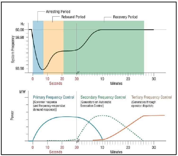
Acknowledgements

We would like to acknowledge the members of the core team dedicated to developing this report
on grid energy storage: Imre Gyuk (OE), Mark Johnson (ARPA-E), John Vetrano (Office of
Science), Kevin Lynn (EERE), William Parks (OE), Rachna Handa (OE), Landis Kannberg
(PNNL), Sean Hearne & Karen Waldrip (SNL), Ralph Braccio (Booz Allen Hamilton).
Table of Contents

Acknowledgements....................................................................................................................................... 1
Executive Summary ....................................................................................................................................... 4
1.0 Introduction .......................................................................................................................................... 7
2.0 State of Energy Storage in US and Abroad .......................................................................................... 11
3.0 Grid Scale Energy Storage Applications .............................................................................................. 20
4.0 Summary of Key Barriers ..................................................................................................................... 30
5.0 Energy Storage Strategic Goals .......................................................................................................... 32
6.0 Implementation of its Goals ................................................................................................................ 36
7.0 Actions Specific to Technology Development ..................................................................................... 46
8.0 Goals and Actions Specific to Analysis ................................................................................................ 49
9.0 Energy Storage Technology Standardization ........................................................................................ 52
Bibliography ................................................................................................................................................ 52
Appendix A: Short Description of DOE Office Programs on Storage ......................................................... 55
   Office of Science ..................................................................................................................................... 55
   Energy Efficiency and Renewable Energy (EERE) .................................................................................... 57
   Advanced Research Projects Agency – Energy (ARPA‐E) ........................................................................ 58
   Office of Electricity Delivery and Energy Reliability ................................................................................ 60
   Other Federal Agencies – Energy Storage R&D Activities....................................................................... 62
       Department of Defense ...................................................................................................................... 62
       National Science Foundation .............................................................................................................. 64
Appendix B ‐ ARRA Energy Storage Demonstration Projects ..................................................................... 65

                                                                                                                                                                   2
Table of Figures and Tables
Figure 1 – Rated Power of US Grid Storage projects (includes announced projects) ................................ 11
Figure 2 – Number of US installations, grouped by capacity ...................................................................... 11
Figure 3 ‐‐ Maturity of electricity storage technologies ............................................................................. 16
Figure 4 ‐‐ System Load Without and With Regulation .............................................................................. 23
Figure 5 ‐‐ The Sequential Actions of Primary, Secondary, and Tertiary Frequency Controls Following the
Sudden Loss of Generation and Their Impacts on System Frequency ...................................... 24
Figure 6 ‐‐ Storage for Reserve Capacity ..................................................................................................... 25
Figure 7 ‐‐ Storage Technology Cost ........................................................................................................... 35
Figure 8 ‐‐ Role of DOE Offices in Technology Development, Maturation and Commercialization ........... 36
Figure 9 ‐‐ Summary Timeline of DOE Initiatives ..………………………………………………………………………………….40
Figure 10 ‐‐ Steps to Drive Down Cost in Technology Development .......................................................... 46
Table 1 ‐‐ International Landscape of Grid Storage .................................................................................... 15
Table 2 – Installations of Batteries.............................................................................................................. 17
Table 3 ‐‐ Technology Types Source: Advancing Energy Storage ............................................................... 19
Table 4 – Electric Grid Energy Storage Services .......................................................................................... 21
Table 5 ‐‐ Applications by Technology Type ............................................................................................... 29
Table 6 ‐‐ Strategy Summary for DOE Energy Storage ................................................................................ 34
Table 7 ‐‐ Role of DOE Offices in Grid Energy Storage ................................................................................ 37
Table 8 ‐‐ Specific Activities in Support of the Energy Storage Strategy .................................................... 38Executive Summary
Modernizing the electric system will help the nation meet the challenge of handling
projected energy needs—including addressing climate change by integrating more energy
from renewable sources and enhancing efficiency from non-renewable energy processes.
Advances to the electric grid must maintain a robust and resilient electricity delivery
system, and energy storage can play a significant role in meeting these challenges by
improving the operating capabilities of the grid, lowering cost and ensuring high
reliability, as well as deferring and reducing infrastructure investments. Finally, energy
storage can be instrumental for emergency preparedness because of its ability to provide
backup power as well as grid stabilization services.
At present, the U.S. has about 24.6GW (approx. 2.3% of total electric production
capacity) of grid storage, 95% of which is pumped storage hydro.1 Europe and Japan
have notably higher fractions of grid storage. Pursuit of a clean energy future is
motivating significantly increased storage development efforts in Europe and Asia, as
well as the U.S.
Energy storage technologies—such as pumped hydro, compressed air energy storage,
various types of batteries, flywheels, electrochemical capacitors, etc., provide for
multiple applications: energy management, backup power, load leveling, frequency
regulation, voltage support, and grid stabilization. Importantly, not every type of storage
is suitable for every type of application, motivating the need for a portfolio strategy for
energy storage technology.
There are four challenges related to the widespread deployment of energy storage: cost
competitive energy storage technologies (including manufacturing and grid integration),
validated reliability & safety, equitable regulatory environment, and industry acceptance.
Issues that are being explored in this paper focus on reducing system costs through
targeted application of science and engineering research and development for new
storage concepts, materials, components and systems (including manufacturability and
standardization). Developers should consider technical risk mitigation, for controlling
the uncertainties at the early stage of deployment so that cost estimates and operational
practices can develop based upon well-grounded and fully understood data. Ongoing
research and development, from fundamental science of energy storage mechanisms to
1
http://www.energystorageexchange.org/ (All data cited in this paragraph is current as of August 2013). Note that the
database has only verified the details of 121 of these deployments, with the details on the remaining projects in various
stages of verification.
4the early stage development of platform technologies should also be considered in
support of these challenges. Industrial standards for grid storage are in their infancy.
Industry acceptance could also gain ground when we reduce the uncertainty surrounding
how storage technology is used, and monetized, at scale. Ultimately, it will be the
experience and real-world use of storage that will provide the confidence and desire to
expand installed storage.
The expansion of the electricity system can be accelerated by the widespread deployment
of energy storage, since storage can be a critical component of grid stability and
resiliency. The future for energy storage in the U.S. should address the following
issues: energy storage technologies should be cost competitive (unsubsidized) with
other technologies providing similar services; energy storage should be recognized for
its value in providing multiple benefits simultaneously; and ultimately, storage
technology should seamlessly integrate with existing systems and sub-systems leading
to its ubiquitous deployment.
In reviewing the barriers and challenges, and the future for energy storage, a strategy that
would address these issues should comprise three broad outcome-oriented goals:
1. Energy storage should be a broadly deployable asset for enhancing renewable
penetration – specifically to enable storage deployment at high levels of new
renewable generation
2. Energy storage should be available to industry and regulators as an effective option to
resolve issues of grid resiliency and reliability
3. Energy storage should be a well-accepted contributor to realization of smart-grid
benefits – specifically enabling confident deployment of electric transportation and
optimal utilization of demand-side assets.
To realize these outcomes, the principal challenges to focus on are:
Cost competitive energy storage technology - Achievement of this goal requires
attention to factors such as life-cycle cost and performance (round-trip efficiency,
energy density, cycle life, capacity fade, etc.) for energy storage technology as
deployed. It is expected that early deployments will be in high value applications, but
that long term success requires both cost reduction and the capacity to realize revenue
for all grid services storage provides.
Validated reliability and safety - Validation of the safety, reliability, and
performance of energy storage is essential for user confidence.
Equitable regulatory environment – Value propositions for grid storage depend on
reducing institutional and regulatory hurdles to levels comparable with those of other
grid resources.
5 Industry acceptance – Industry adoption requires that they have confidence storage
will deploy as expected, and deliver as predicted and promised.
DOE is addressing these challenges in the following ways:
Challenge/Goal Strategy Summary
Cost competitive energy Targeted scientific investigation of fundamental materials, transport
storage technology processes, and phenomena enabling discovery of new or enhanced
storage technologies with increased performance
Materials and systems engineering research to resolve key technology
cost and performance challenges of known and emerging storage
technologies (including manufacturing)
Seeded technology innovation of new storage concepts
Development of storage technology cost models to guide R&D and
assist innovators
Resolution of grid benefits of energy storage to guide technology
development and facilitate market penetration
Validated reliability and R&D programs focused on degradation and failure mechanisms and
safety their mitigation, and accelerated life testing
Development of standard testing protocols and independent testing of
prototypic storage devices under accepted utility use cases
Track, document, and make available performance of installed storage
systems
Equitable Regulatory Collaborative public-private sector characterization and evaluation of
Environment grid benefits of storage
Exploration of technology-neutral mechanisms for monetizing grid
services provided by storage
Development of industry and regulatory agency-accepted standards for
siting, grid integration, procurement, and performance evaluation
Industry acceptance Collaborative, co-funded field trials and demonstrations enabling
accumulation of experience and evaluation of performance – especially
for facilitating renewable integration and enhanced grid resilience
Adaptation of industry-accepted planning and operational tools to
accommodate energy storage
Development of storage system design tools for multiple grid services
61.0 Introduction
Modernizing the electric grid will help the nation meet the challenge of handling
projected energy needs—including addressing climate change by relying on more energy
from renewable sources—in the coming decades, while maintaining a robust and resilient
electricity delivery system. By some estimates, the United States will need somewhere
between 4 and 5 tera kilowatt-hours of electricity annually by 2050.2 Those planning and
implementing grid expansion to meet this increased electric load face growing challenges
in balancing economic and commercial viability, resiliency, cyber-security, and impacts
to carbon emissions and environmental sustainability. Energy storage systems (ESS) will
play a significant role in meeting these challenges by improving the operating capabilities
of the grid as well as mitigating infrastructure investments. ESS can address issues with
the timing, transmission, and dispatch of electricity, while also regulating the quality and
reliability of the power generated by traditional and variable sources of power. ESS can
also contribute to emergency preparedness. Modernizing the grid will require a
substantial deployment of energy storage. In the past few years, the urgency of energy
storage requirements has become a greater, more pressing issue that is expected to
continue growing over the next decade:
California enacted a law in October 2010 requiring the California Public Utilities
Commission (CPUC) to establish appropriate 2015 and 2020 energy storage
procurement targets for California load serving entities, if cost effective and
commercially viable by October 2013 (AB 2514). In February 2013, the CPUC
determined that Southern California Edison must procure 50 MW of energy
storage capacity by 2021 in Los Angeles area. Additionally, in June 2013, the
CPUC proposed storage procurement targets and mechanisms totaling 1,325 MW
of storage. Other States are looking to the example that California is setting, and
Congress has introduced two bills that establish incentives for storage
deployment.3
The increasing penetration of renewable energy on the grid to meet renewable
portfolio standards (RPS) may be linked with greater deployment of energy
storage. Storage can “smooth” the delivery of power generated from wind and
solar technologies, in effect, increasing the value of renewable power.
Additionally, when energy storage is used with distributed generation, it can
improve the reliability of those assets by providing power-conditioning value, and
enables increased renewable penetration to help contribute to meeting state RPS.
2
For a table of several such estimates, see Hostick, D.; Belzer, D.B.; Hadley, S.W.; Markel, T.; Marnay, C.; Kintner-
Meyer, M. (2012). End-Use Electricity Demand. Vol. 3 of Renewable Electricity Futures Study. NREL/TP-6A20-
52409-3. Golden, CO: National Renewable Energy Laboratory.
3
The bills before congress are S. 1030 (STORAGE Act ) and S. 795 (MLP Parity Act). Details on the California bill
(AB 2514) can be found on the CPUC website: http://www.cpuc.ca.gov/PUC/energy/electric/storage.htm
7 Energy storage is already near commercial viability in augmenting power
management and frequency regulation techniques. Large flywheel installations
and power monitoring software have combined to make flywheel installation
useful in ensuring that intermittent sources and variable load demands maintain a
60 Hz frequency, storage could be an alternative method of providing spinning
reserve or curtailment which could improve the efficiency of infrastructure and
reduce greenhouse gas emissions caused by wasteful excess capacity and
lowered heat-rates associated with excessive plant cycling.
Energy storage can reduce the need for major new transmission grid construction
upgrades as well as augment the performance of existing transmission and
distribution assets. DOE estimates that 70% of transmission lines are 25 years or
older, 70% of power transformers are 25 years or older, and 60% of circuit
breakers are more than 30 years old.4 Extending the capability of the transmission
grid—for example by pre-positioning storage on the load side of transmission
constraint points—makes the grid more secure, reliable, and responsive.
Additionally, distributed storage can reduce line-congestion and line-loss by
moving electricity at off-peak times, reducing the need for overall generation
during peak times. By reducing peak loading (and overloading) of transmission
and distribution lines, storage can extend the life of existing infrastructure.
Moreover, as the nation moves towards the electrification of the transportation
sector, energy storage for vehicles, and the integration of energy between vehicles
and the grid, will be critical. The focus on storage is not only for the deployment
of batteries in vehicles, but also for potential second-life applications for electric
vehicle (EV) batteries. For example, Project Plug-IN, a large scale public/private
EV initiative based in Indianapolis, involving Duke Energy, is exploring the best
customer use for stationary applications in homes, neighborhoods, and
commercial buildings. This pilot project is being used to help validate the
business models for future commercialization of storage technologies.
Energy storage will also play a significant role in emergency preparedness and
increasing overall grid resilience. An August 2013 White House report,5 written
in conjunction with the Office of Electricity Delivery & Energy Reliability,
details the integral role that energy storage will play in enhancing grid resilience
and robustness related to weather outages and other potential disruptions.6
4
Fitch Ratings, “Frayed Wires: US Transmission System Shows Its Age,” 2006
5
“Economic Benefits Of Increasing Electric Grid Resilience To Weather Outages” August 12, 2013. Available at:
http://energy.gov/sites/prod/files/2013/08/f2/Grid%20Resiliency%20Report_FINAL.pdf
6
See also “Storm Reconstruction: Rebuild Smart: Reduce Outages, Save Lives, and Protect Property,” NEMA,
National Electrical Manufacturers Association, 2013; and “ Recommendations to Improve the Strength and Resilience
of the Empire State’s Infrastructure,” NYS 2100 Commission, 2012.
8 Energy storage is poised to grow dramatically, requiring large investment in
manufacturing capacity and jobs. According to an Information Handling
Services, Cambridge Energy Research Associates (IHS CERA) report, the energy
storage business could grow from $200 million in 2012 to a $19 billion industry
by 2017.7
The Department of Energy serves a vital role in resolving major challenges that are
hampering widespread deployment of grid energy storage. Teaming with industry, State
and municipal governments, academia, and other Federal agencies, DOE supports the
discovery of new technologies to improve cost and performance of grid energy storage,
spur technology innovation and incorporation into improved storage products, remove
unnecessary barriers to deployment, and facilitate the establishment of industry-wide
standards to ease widespread adoption of storage. These activities can help to catalyze
the timely, material, and efficient transformation of the nation’s energy system and
secure U.S. leadership in clean energy technologies. DOE’s 2011 Strategic Plan has
identified a number of targeted outcomes in support of this goal, the most relevant to this
mission includes reducing energy storage costs 30% by 2015 and supporting the
integration of Plug-in Hybrid Electric and Battery Electric Vehicles as they shift load
profiles8.
Storage technology can help contribute to overall system reliability as large quantities of
wind, solar, and other renewable energy sources continue to be added to the nation’s
generation assets, furthering the goals of reducing greenhouse gas emissions and
increasing energy security. Additionally, storage technology will be an instrumental tool
in managing grid reliability and resiliency by regulating variable generation and
improving microgrid and smart-grid functionality. For micro- and smart-grid
technologies, storage can provide redundancy options in areas with limited transmission
capacity, transmission disruptions, or volatile demand and supply profiles.
The Department’s electric energy storage program can create economic opportunities, as
well. A strong storage market will foster a robust manufacturing base of advanced
electric energy storage devices in the U.S., and this capability can be leveraged for export
opportunities in the robust foreign market for storage. Further, by enabling more
efficient adoption of renewable energy sources in the US, storage can help promote US
energy independence and reduce carbon emissions.
Overview of this Report –This report sets out potential options to improve energy
storage. It also presents a number of specific actions that could help maintain both
7
IMS Research (now owned by IHS-CERA) report ‘The Role of Energy Storage in the PV Industry – World – 2013
Edition’.
8
U.S. Department of Energy ‘Strategic Plan May 2011’
(http://energy.gov/sites/prod/files/2011_DOE_Strategic_Plan_.pdf) page 15 and page 17
9scientific advancements and a pipeline of project deployments. This report does not
address new policy actions, nor does it specify budgets and resources for future
activities.
Section 2.0 of this report describes the present state of energy storage in the US, as well
as international projects that could serve as a near-term template for US investment and
growth. Section 3.0 describes the present state of technology for energy storage,
including the applications and opportunities for each technology type. Section 4.0
discusses the barriers and challenges to widespread adoption of grid-storage techniques,
as well as other concerns that will need to be addressed. Sections 5.0 and 6.0 highlight
ideas on how to promote and advance energy storage over the next three to five years,
ranging from promoting basic research to promoting and analyzing present and future
grid-storage markets. Section 7.0 discusses goals related to technology developments
while section 8.0 discusses goals related to analysis. Finally section 9.0 addresses
standardization and DOE’s ongoing activities. The appendices detail storage R&D
programs at relevant DOE offices and several Federal agencies and provides a listing of
American Recovery and Reinvestment Act of 2009 (ARRA) funded energy storage
projects.
102.0 State of Energy Storage in US and Abroad
An interactive database9 created and maintained by DOE provides a snapshot of the
extent and range of energy storage systems deployments worldwide. As of August 2013,
the database reported 202 storage system deployments in the US with a cumulative
operational capability of 24.6 GW, with a mix of storage technologies including pumped
hydro, various types of batteries, and flywheels.10 The contribution of each technology to
the overall operational capability is shown in Figure 1. At 95%, pumped hydro clearly
dominates due to its larger unit sizes and longer history as the technology of choice for
energy storage by the electric utility sector. Other technologies such as compressed air
energy storage (CAES), thermal energy storage, batteries, and flywheels constitute the
remaining 5% of overall storage capability.
Figure 1 – Rated Power of US Grid Storage projects (includes announced projects)
Thermal Battery ‐
Storage ‐ 26%, 304
36%, 431 MW
Pumped Hydro ‐ Flywheel
MW
95%, 23.4 GW 3%, 40 MW
Other ‐
1.2 GW Compressed Air
‐ 35%, 423 MW
Similarly, Figure 2 shows the wide range of system sizes that have been deployed. The
rated power of the various projects ranges from small, residential scale (7 projects are
listed as 10 kW or below—this is a reporting artifact, as there are likely many small
systems not in the database) to large, utility scale systems of 1 MW or more.11
Figure 2 – Number of US installations, grouped by capacity
9
: http://www.energystorageexchange.org/ (All data cited in this paragraph is current as of August 2013)
10
Note that the database has only verified the details of 121 of these deployments, with the details on the remaining
projects in various stages of verification.
11
This information also was accessed in August 2013, and can be found at: http://www.energystorageexchange.org/
11Installations by Rated Power (includes
announced)
60
40 57
42 43
20
7 19 23 11
0
Note, systems 10 kW or below are likely
to be undercounted in this database
Installations
Energy storage systems and the services they provide can be used in regulated and
deregulated markets. However, for energy storage technologies used on the grid,
regulatory policies and rules provide the framework for the business case and economics
of storage systems. Other incentives, such as tax structures and asset depreciation rates
significantly affect the economics for storage projects. All the electrical grid-connected
storage services, market opportunities, cost-recovery methods, cost-effectiveness criteria,
incentives, and rebates are governed by a well-established regulatory oversight. The
Federal Energy Regulatory Commission (FERC) regulates interstate transactions, while
State entities such as Public Utility Commissions (PUCs) regulate utility management,
operations, electricity rate structures, and capacity acquisition within their State’s
jurisdiction. Additionally, in some regions Independent System Operators (ISOs) provide
oversight of transmission and generation. This multi-level oversight impacts the growth
of the storage industry because policies can create or inhibit market opportunities for
electricity storage and may determine how, and if, they will be compensated.
New policies are being implemented at the State level, being discussed and rolled out at
the national level, and previous investments are coming to fruition and can shape future
investment.12 As an example of the influence of policy structure on the adoption of
storage, FERC Order 755 helps structure payments and set contracts for frequency
regulation, and is changing the market for frequency-regulation applications. PJM was
the first Regional Transmission Organization (RTO) to adopt Order 755, and the results
have significantly improved the commercial viability of frequency regulation. Further,
the frequency regulation market will likely continue to mature, as several other RTOs
have or are scheduled to adopt Order 755. For example, Midcontinent Independent
System Operator (MISO) also adopted the order at the end of 2012, while the California
and New York Independent System Operators (CAISO & NYISO) adopted the mandate
12
Policy information come from the Bloomberg New Energy Finance report on storage dated June, 2013 and the
Sandia National Laboratories database: http://www.energystorageexchange.org/
12in mid-2013 and the Independent System Operator - New England (ISONE) will begin
following the Order in January 2014.13 Additionally, Congress continues to debate two
bills14 that would help codify the cost structure for storage-related subsidies and
partnership taxation structures for investment in storage and storage-related activities.
In addition to national developments, California, Texas, New York, Hawaii, and
Washington have all proposed significant policies on storage. California has enacted
laws that make energy storage more viable from a cost and regulatory perspective and
give the California Public Utilities Commission (CPUC) the power to mandate certain
regional penetration levels of storage. The CPUC recently mandated that 50 MW of
storage be installed in the Los Angeles Basin by 2020, as well as a top-line mandate of
1.3 GW of storage for the entire state.15 The Texas legislature has enacted SB 943 that
classifies energy storage technologies alongside generation equipment, and the Public
Utility Commission of Texas adopted key aspects of the bill as well as clarified rules,
requirements, and definitions for energy storage 16. In 2010, New York State established
NY Battery and Energy Storage Technology Consortium (NY-BEST),17 a public-private
partnership that researches storage technology and manufacturing, aids energy storage
organizations as well as potential stakeholders, and advocates for policies and programs
that could improve energy storage. Additionally, Washington State enacted two laws18
related to energy storage: the first enables qualifying utilities to credit energy storage
output of renewable sourced energy at 2.5 times the normal value; the second requires
electric utilities to include energy storage in all integrated resource plans.
On the national level, several projects that were funded under ARRA through the Smart-
Grid Demonstration Grant program are coming online in 2013, and their performance has
the potential to guide future investment decisions and policy initiatives. In total, an
estimated 59 MW of storage capacity is scheduled to come online in 2013, accounting for
7 of the 16 ARRA-funded projects. In addition, hydrogen fuel cells for backup power are
being used in more than 800 units associated with telecom towers in the U.S., as a result
of ARRA funding.19
Internationally, Japan has pursued the development and deployment of energy storage to
balance the variability of load on its nuclear power plants. After completing an initial
phase of building pumped hydro storage plants, Japan pursued development of other
storage technologies. Its most prominent accomplishment was the commercial
13
See Bloomberg New Energy Finance H1 2013, page 8.
14
S. 795 and S. 1845
15
Note that this number includes some of the projects funded by the 2009 ARRA that have yet to come online; these
projects total 334MW, or roughly 1/4th of the total target.
16
http://www.capitol.state.tx.us/billlookup/history.aspx?legsess=82r&bill=sb943
17
http://www.ny-best.org/
18
HB 1289 and HB1296
19
http://www.nrel.gov/hydrogen/cfm/pdfs/arra_deployment_cdps_q12013_4web.pdf
13development of high temperature sodium-sulfur batteries through a sustained R&D
program that spanned two decades. 20 Today, Japan-based NGK is the only source of
sodium-sulfur batteries and as of 2012, NGK had over 450 MW of sodium sulfur storage
systems installed. 21
China and India are also pursuing energy storage programs to support the rapid growth in
their electric energy needs. Energy storage could serve many grid needs in both China
and India to bridge the gap between available generation and customer loads during
system peaks and as a distributed resource on the customer-side of the meter. In one
example, India is aggressively pursuing energy storage as a secure power resource for
more than 300,000 telecom towers, and announced a $40 million contract in July 2013
for Li-ion battery energy storage systems to meet that need. This example has the
potential to demonstrate telecom towers as a “first market” for storage technologies
developed and manufactured in the U.S.22
Table 1 describes some of the country-specific highlights of international grid storage.
20
See Bloomberg New Energy Finance H1 2013, pages 19‐22.
21
See Bloomberg New Energy Finance H1 2013, page 23.
22
http://www.saftbatteries.com/press/press‐releases/saft‐receives‐%E2%82%AC35m‐orders‐reliance‐jio‐
infocomm‐limited‐rjil‐li‐ion‐telecom
14Table 1 - International Landscape of Grid Storage
Country Storage Projects Other Issues Technology & Applications
Targets23
Italy 75 MW 51 MW of Storage Italy has substantial renewables capacity relative to 35 MW to be Sodium-Sulfur
Commissioned by 2015 grid size, and the grid is currently struggling with Batteries for long-duration
Additional 24 MW funded reliability issues; additional renewables capacity will discharge
only exacerbate this problem Additional capacity is focused
on reliability issues and
frequency regulation
Japan 30 MW Approved 30 MW of Potential decommissioning of nuclear fleet Primarily Lithium ion batteries
Lithium-ion battery Large installation of intermittent sources - est. 9.4 GW Recently increased regulatory
installations of solar PV installed in 2013 alone approved storage devices from
Several isolated grids with insufficient transmission 31 to 55
infrastructure during peak demand periods
South Korea 154 MW 54 MW lithium-ion Significant regulatory/performance issues with nuclear Reliability & UPS
batteries fleet
100 MW CAES
Germany $260m for $172m already Decommissioning entire nuclear fleet; Large (and Hydrogen; CAES & Geological;
grid apportioned to announced expanding) intermittent renewable generation Frequency Regulation
storage projects capabilities
Over 160 energy storage pilot projects
Awaiting information on energy storage mandates
Canada - Announced 1st frequency - -
regulation plant
UK - 6 MW multi-use battery Other small R&D and Demonstration projects Battery will perform both load
shifting and frequency
regulation applications
23
Information in this table comes from Bloomberg New Energy Finance’s Energy Storage Market Outlook, June, 28, 2013, as well as the DOE database on Energy Storage
Projects referenced earlier. Conversions based on 1 euro = $1.30
15Technology Overview
Storage systems can be designed with a broad portfolio of technologies such as pumped hydro,
compressed air energy storage CAES, a large family of batteries, flywheels, and superconducting
magnetic energy storage (SMES). Each technology has its own performance characteristics that
makes it optimally suitable for certain grid services and less so for other grid applications. This
ability of a storage system to match performance to different grid requirements also allows the
same storage system to provide multiple services. This gives storage systems a greater degree of
operational flexibility that cannot be matched by other grid resources, such as combustion
turbines or a diesel generator. The ability of a single storage system to meet multiple
requirements also makes it feasible to capture more than one value stream, when possible, to
justify its investment. While the categorization of “deployed,” “demonstrated,” and “early
stage,” is often blurred, and changes over time, Figure 3 groups technologies based on their
present degree of maturity.24
Figure 3 - Maturity of electricity storage technologies
Some early stage
Deployed Demonstration
technologies
Advanced Pb‐acid and Flow
Pumped hydro Adiabatic CAES
batteries
Compressed Air Energy Superconducting Magnetic
Hydrogen
Storage (CAES) Energy Storage (SMES)
Batteries
Electrochemical Capacitors Synthetic Natural Gas
(NaS, Li‐ion, Pb‐Acid)
Flywheels
This portfolio of electricity storage technologies can provide a range of services to the electric
grid and can be positioned around their power and energy relationship. Established large-scale
technologies, such as CAES and pumped hydro, are capable of discharge times in tens of hours
and with high module sizes that reach 1,000 MW. Pumped hydroelectric energy storage is a
large, mature, and commercial utility-scale technology currently used at many locations in the
United States and around the world. Pumped hydro currently employs off-peak electricity to
pump water from a reservoir up to another reservoir at a higher elevation. When electricity is
24
Several technologies that are still in the early stages of research have been omitted, as they are unlikely to be commercially
viable within the next 3-5 years.
16needed, water is released from the upper reservoir through a hydroelectric turbine into the lower
reservoir to generate electricity. New capabilities of pumped hydro, through the use of variable
speed pumping, is opening up the potential for the provision of additional services that may be
used to assist in the integration of variable generation sources. Projects may be practically sized
up to 4,000 MW and operate at about 76%–85% efficiency, depending on design. Pumped hydro
plants have long lives, on the order of 50-60 years. As a general rule, a reservoir one kilometer in
diameter, 25 meters deep, and having an average head of 200 meters would hold enough water to
generate 10,000 MWh. CAES systems are not as “mature” as pumped hydro, but are similar in
their use as they store energy in the form of pressurized air, usually in underground caverns.
However, both CAES and pumped hydro have very specific geographic requirements making
their installation site-dependent.
For example a CAES plant can enhance the grid to allow successful integration of significant
amounts of renewable resources while enhancing the transmission system and providing grid
stability during intermittent operations. It will also provide ancillary services such as regulation,
capacity reserve, and reactive power for voltage support with the size and flexibility that will
enable large amounts of energy to be stored and discharged for use to maintain and improve the
grid system reliability and relieving transmission congestion. Energy storage, such as CAES
enhances the grid by making the grid more efficient, which will assist in achieving the full
potential of renewables and will provide an industry model for a grid-enabled diversified energy
portfolio.
In contrast to the capabilities of these two technologies, various electrochemical batteries and
flywheels are positioned around lower power and shorter discharge times, ranging from a few
seconds to six hours, and these technologies can generally be built without specific geographical
features at the site.
Table 2 – Installations of Batteries
There are several different electrochemical
Battery Type Number of Largest
1MW+ Installation battery technologies that are currently available
Deployments for commercial applications. These technologies
Lithium Ion 15 40 have been successfully deployed in both
Sodium Sulfur 11 4* distributed and centralized applications in various
sizes. However, they have not yet realized
Lead Acid 9 36
widespread deployment due to challenges in
energy density, power performance, lifetime,
*There are two 4MW deployments
charging capabilities, safety, and system cost. The
more robust technologies include lithium-ion (Li-ion), sodium sulfur (NaS), and lead acid
batteries, including lead carbon batteries. Li-ion batteries tend to be best suited for relatively
short discharges (under two hours) and do not handle deep-discharges well, so these batteries are
more suited to power-management operations such as frequency regulation or as an
17uninterruptible power source (UPS). NaS batteries are somewhat behind Li-ion battery technology in terms of energy and power, but they can maintain longer discharges (four to eight hours) and may be more suitable for load leveling and price arbitrage operations. Lead acid batteries, a mature technology with good battery life, are relatively cheap; however, the low energy density and short cycle time are challenges to large-scale deployment. Also, there are other novel chemistries being developed such as sodium-ion. Flywheels are currently commercially deployed primarily for frequency regulation. Flywheel plants take in electricity and convert it into spinning discs, which can be sped up or slowed down to rapidly shift energy to or from the grid, which ensures steady power (60 Hz) supplied to the grid. Flow batteries were invented by US utilities specifically to provide MW-scale storage capacity beyond the geographic constraints of hydroelectric facilities. Significant US industry and DOE investment over the past 40 years has led to a mature understanding of the advantages and limitations of available chemistries, as well as more recent breakthroughs in performance and thermal tolerance. However, due to lack of MW-scale field history, flow batteries have not gained substantial commercial traction in the US, with various flow-battery technologies still in the demonstration phase, and the largest single operational system at 0.6 MW.25 However, recently we are seeing flow batteries projects launch oversees with systems up to 5MW in size and a total deployed capacity of 20MW. China and Japan are currently funding over $200MM in flow battery projects and Europe is following suit with numerous smaller projects. The interest in flow batteries stems from several potential advantages over traditional batteries, primarily the liquid suspension and separation of the chemical components that allow for full charge utilization with a high number of discharge cycles and extremely long unit life. Flow batteries have faced obstacles related to their low energy density and integrated design requirements that make it difficult to compete at sub-MW scale. With recent advances in these areas, flow batteries may be commercially deployable in the US within the next few years if MW-scale projects similar to current ARRA projects succeed. Another technology in the demonstration/applied research phase is superconductive magnetic energy storage (SMES). Each unit employs a superconducting coil, a power conditioning system, and a cooling system. The cooling system chills the coil below the superconducting transition temperature, so that electrical currents flow without resistance or loss of energy. Energy is stored inductively in the DC magnetic field of a solenoid, as long as the temperature remains sufficiently low. Most SMES technologies currently have a high cycle-life and power density, but low energy density and high cost that make them best suited for supplying short bursts of electricity into the energy system. Superconductors currently have the highest round- 25 This is the Prudent Energy VRB-ESS® - Gills Onions, California. The information on US installations comes from the DOE Energy Storage database referenced earlier. 18
trip efficiency of any storage device, though they are costly to manufacture and maintain and
they have only a limited number of small demonstrations.

Electrochemical capacitors (EC) technology stores direct electrical charge in the material, rather
than converting the charge to another form, such as chemical energy in batteries or magnetic
field energy in SMES; this makes the storage process reversible, efficient, and fast. As such, EC
can be useful in power-quality applications such as frequency regulation, and voltage
stabilization. The devices may have longer useful lives since there is little breakdown in the
capacitors ability to store energy electrostatically. Currently, electrochemical capacitors can store
significantly more energy than dielectric and electrolytic capacitors; however, EC technology is
still cost prohibitive.26

Thermochemical energy storage is an emerging technology that uses reversible chemical
reactions to store heating or cooling capacity in chemical compounds. The promise of
thermochemical storage is the tremendous energy densities that it can achieve over most other
storage types, ranging from 5 to 20 times greater than conventional storage. Due to its relatively
high energy density potential, a significant research and development effort is currently being
focused on this type of thermal energy storage, though deployments are limited.

Hydrogen systems, as with the other storage technologies, require careful analysis to fully
capture the value stream. Multiple components such as electrolyzers, fuel cells, or hydrogen
oxygen turbines coupled with storage, either underground in geologic formations or above
ground in hydrogen tanks, can be used in grid systems. Hydrogen can also allow for the
decoupling of electricity production and storage resulting in flexible operation. While round trip
energy efficiencies might be at a level of 40%, this relatively low efficiency is balanced by
energy storage potential that may last days, to weeks, or longer.

Table 3 summarizes the state of most energy storage technologies.

                 Table 3 - Technology Types Source: Advancing Energy Storage
      Technology       Primary Application   What we know currently          Challenges
CAES                         • Energy management               • Better ramp rates than gas      • Geographically limited
                             • Backup and seasonal               turbine plants                  • Lower efficiency due to
                               reserves                        • Established technology in         roundtrip conversion
                             • Renewable integration             operation since the 1970’s      • Slower response time than
                                                                                                   flywheels or batteries
                                                                                                 • Environmental impact
Pumped Hydro                 • Energy management               • Developed and mature            • Geographically limited
                             • Backup and seasonal               technology                      • Plant site
                               reserves                        • Very high ramp rate             • Environmental impacts
                             • Regulation service also         • Currently most cost effective   • High overall project cost
                               available through                 form of storage
                               variable speed pumps

26
     Source: http://web.anl.gov/energy-storage-science/publications/EES_rpt.pdf

19
Technology Primary Application What we know currently Challenges
Fly wheels • Load leveling • Modular technology • Rotor tensile strength
• Frequency regulation • Proven growth potential to limitations
• Peak shaving and off utility scale • Limited energy storage time
peak storage • Long cycle life due to high frictional losses
• Transient stability • High peak power without
overheating concerns
• Rapid response
• High round trip energy
efficiency
Advanced Lead- • Load leveling and • Mature battery technology • Limited depth of discharge
Acid regulation • Low cost • Low energy density
• Grid stabilization • High recycled content • Large footprint
• Good battery life • Electrode corrosion limits
• useful life
NaS • Power quality • High energy density • Operating Temperature
• Congestion relief • Long discharge cycles required between 250° and
• Renewable source • Fast response 300° C
integration • Long life • Liquid containment issues
• Good scaling potential (corrosion and brittle glass
seals)
Li-ion • Power quality • High energy densities • High production cost -
• Frequency regulation • Good cycle life scalability
• High charge/discharge • Extremely sensitive to over
efficiency temperature, overcharge and
internal pressure buildup
• Intolerance to deep discharges
Flow Batteries • Ramping • Ability to perform high • Developing technology, not
• Peak Shaving number of discharge cycles mature for commercial scale
• Time Shifting • Lower charge/discharge development
• Frequency regulation efficiencies • Complicated design
• Power quality • Very long life • Lower energy density
•
SMES • Power quality • Highest round-trip efficiency • Low energy density
• Frequency regulation from discharge • Material and manufacturing
cost prohibitive
Electrochemical • Power quality • Very long life • Currently cost prohibitive
Capacitors • Frequency regulation • Highly reversible and fast
discharge
Thermochemical • Load leveling and • Extremely high energy • Currently cost prohibitive
Energy Storage regulation densities
• Grid stabilization
3.0 Grid Scale Energy Storage Applications
Until the mid-1980s energy storage was viewed by the electric utilities as a means to time
shift energy produced by coal and nuclear units during off-peak hours to displace energy
that would be produced from other more expensive fuels during on-peak periods. Several
factors, including environmental concerns in building large pumped hydro plants and the
20emergence of other storage technologies using batteries and flywheels, introduced the
viability of using storage to provide other grid services.27
The 2013 edition of the DOE/EPRI Electricity Storage Handbook describes eighteen
services and applications in five umbrella groups, as listed in Table 4. The services and
applications identified in this table show that energy storage can be used to support
generation, transmission, and distribution, as well as customer-side-of-the-meter needs of
the grid. This section describes some of the functions most commercially viable and
relevant to the near-term future of the grid. 28
Table 4 – Electric Grid Energy Storage Services
Recognizing energy storage can have multiple services within the grid allows it to
capture multiple benefit streams to offset system costs. The flexibility of storage can be
leveraged to provide multiple or stacked services, or use cases, with a single storage
system that captures several revenue streams to achieve economic viability. How these
services are stacked depends on the location of the system within the grid and the storage
technology used. However, due to regulatory and operating constraints, stacking services
is a process that requires careful planning and should be considered on a case-by-case
basis. The following are brief discussions of some applications of grid energy storage:
Electric Energy Time-shift (Arbitrage)
Electric energy time-shift involves purchasing inexpensive electric energy, available
during periods when prices or system marginal costs are low, to charge the storage
27
A grid service, or application, is a use whereas a benefit connotes a value. A benefit is generally quantified in terms
of a monetary or financial value.
28
A more comprehensive discussion of energy storage applications at all levels can be found in two documents
referenced elsewhere in this report: Eyer (2010) and Chapter 1 of the DOE/EPRI 2013 Handbook.
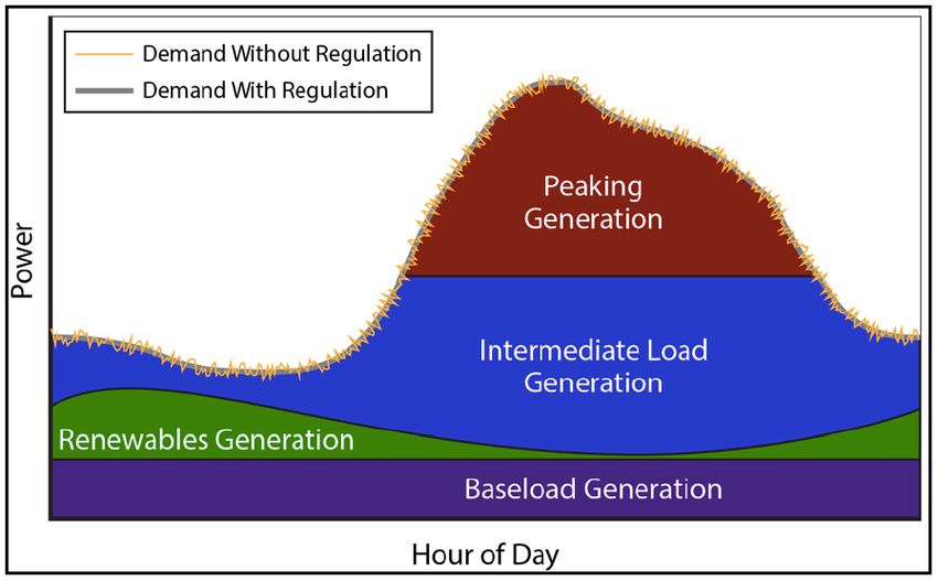
21system so that the stored energy can be used or sold at a later time when the price or costs are high. Alternatively, storage can provide similar time-shift duty by storing excess energy production, which would otherwise be curtailed, from renewable sources such as wind or photovoltaic (PV). The functional operation of the storage system is similar in both cases, and they are treated interchangeably in this discussion. Ancillary Services: Regulation & Frequency Response Regulation is one of the ancillary services for which storage is especially well suited. Regulation involves managing interchange flows with other control areas to match closely the scheduled interchange flows and momentary variations in demand within the control area. The primary reasons for including regulation in the power system are to maintain the grid frequency and to comply with the North American Electric Reliability Council’s (NERC’s) Real Power Balancing Control Performance (BAL001) and Disturbance Control Performance (BAL002) Standards, which are mandatory reliability standards approved by FERC Regulation is used to reconcile momentary differences caused by fluctuations in generation and loads. Regulation is used for damping of that difference. Consider the example shown in Figure 4: the load demand line shows numerous fluctuations depicting the imbalance between generation and load without regulation. The thicker line in the plot shows a smoother system response after damping of those fluctuations with regulation. Generating units that are online and ready to increase or decrease power as needed are used for regulation and their output is increased when there is a momentary shortfall of generation to provide up regulation. Conversely, regulation resources’ output is reduced to provide down regulation when there is a momentary excess of generation. An important consideration in this case is that large thermal base-load generation units in regulation incur some wear and tear when they provide variable power needed for regulation duty. 22
Figure 4 - System Load Without and With Regulation

Frequency response is very similar to regulation, except it reacts to system needs in even
shorter time periods of less than a minute to seconds when there is a sudden loss of a
generation unit or a transmission line. As shown in Figure 5,29 various generator
response actions are needed to counteract this sudden imbalance between load and
generation to maintain the system frequency and stability of the grid. The first response
within the initial seconds is the primary frequency control response of the governor
action on the generation units to increase their power output as shown in the lower
portion of the figure. This is followed by the longer duration secondary frequency control
response by the AGC that spans the half a minute to several minutes shown by the dotted
line in the lower portion of Figure 5. It is important to note that the rate at which the
frequency decays after the triggering event – loss of generator or transmission – is
directly proportional to the aggregate inertia within the grid at that instant. The rotating
mass of large generators and/or the aggregate mass of many smaller generators
collectively determines this inertia.

The combined effect of inertia and the governor actions determines the rate of frequency
decay and recovery shown in the arresting and rebound periods in the upper portion of
Figure 5. This is also the window of time in which the fast-acting response of flywheel
and battery storage systems excels in stabilizing the frequency. The presence of fast-

29
   “Use of Frequency Response Metrics to Assess the Planning and Operating Requirements for Reliable Integration of
Variable Renewable Generation,” Joseph H. Eto (Principal Investigator) et al., LBNL-4142E, Lawrence Berkeley
National Laboratory, Berkeley, CA, December 2010.
http://www.ferc.gov/industries/electric/indus-act/reliability/frequencyresponsemetrics-report.pdf

23
acting storage assures a smoother transition from the upset period to normal operation if
the grid frequency is within its normal range.

 Figure 5 - The Sequential Actions of Primary, Secondary, and Tertiary Frequency
 Controls Following the Sudden Loss of Generation and Their Impacts on System
                                     Frequency

Spinning, Non-Spinning, and Supplemental Reserves

Operation of an electric grid requires reserve capacity that can be called upon when some
portion of the normal electric supply resources become unavailable unexpectedly.

Generally, reserves are at least as large as the single largest resource (e.g., the single
largest generation unit) serving the system and reserve capacity is equivalent to 15% to
20% of the normal electric supply capacity. NERC and FERC define reserves based on
different operating conditions. There are three generic types of reserves: spinning or

24
synchronized reserves30 that can respond within 10 seconds to 10 minutes to service
frequency issues, or generation or transmission outages; non-spinning or non-
synchronized reserves31 that can respond within 10 minutes for use as uninterruptible
and/or curtailable loads; and supplemental reserves that can pick up load within an hour
to back up any disruption to spinning and non-spinning reserves. Importantly for storage,
generation resources used as reserve capacity must be online and operational (i.e., at part
load). Unlike generation, in almost all circumstances, storage used for reserve capacity
does not discharge at all; it just has to be ready and available to discharge when needed.
Reserve capacity resources must receive and respond to appropriate control signals.
Figure 6 shows how storage responds to spinning reserve requirements. The upper plot
shows a loss of generation and the lower plot shows the immediate response with a 30-
minute discharge to provide the reserve capacity until other generation is brought online.
Figure 6 - Storage for Reserve Capacity
Load Following/Ramping Support for Renewables
Electricity storage is eminently suitable for damping the variability of wind and PV
systems and is being widely used in this application. Technically, the operating
requirements for a storage system in this application are the same as those needed for a
storage system to respond to a rapidly or randomly fluctuating load profile. Most
renewable applications with a need for storage will specify a maximum expected up- and
30
Spinning reserve is defined in the NERC Glossary as “Unloaded generation that is synchronized and ready to serve
additional demand.”
31
Non-spinning reserve is not uniformly the same in different reliability regions. It generally consists of generation
resources that are offline, but could be brought online within 10 to 30 minutes and could also include loads that can be
interrupted in that time window.
25You can also read