GW1949 Model Number: US Stove Company
←
→
Page content transcription
If your browser does not render page correctly, please read the page content below
Owner’s Instruction and Operation Manual

                Model Number:
                  GW1949
                                      R

                   Report Number: F20-572
              Certified to 1482-11 (R2015) and
               Certified to ULC-S627-00-REV1
                    Mobile home approved

  * All Pictures In This Manual Are For Illustrative Purposes Only. Actual Product May Vary.                 852489J-0204K

                         Save These Instructions In A Safe Place For Future Reference.

           SAFETY NOTICE: If this heater is not properly installed, a house fire may result. For
           your safety, follow the installation instructions. Never use make-shift compromises
           during the installation of this heater. Contact local building or fire officials about
           permits, restrictions and installation requirements in your area. NEVER OPERATE
           THIS PRODUCT WHILE UNATTENDED.

           CAUTION! Please read this entire manual before you install or use your new room
           heater. Failure to follow instructions may result in property damage, bodily injury, or
           even death. Improper Installation Will Void Your Warranty!

      U.S. Environmental Protection Agency                               CALIFORNIA PROPOSITION 65 WARNING:
Certified to comply with 2020 particulate emissions                  This product can expose you to chemicals including carbon
                     standards.                                      monoxide, which is known to the State of California to cause
                                                                     cancer, birth defects, and/or other reproductive harm. For
                  Do not install in a sleeping room                      more information, go to www.P65warnings.ca.gov
This unit is not intended to be used as a primary source of heat.

                         THIS MANUAL IS SUBJECT TO CHANGE WITHOUT NOTICE.
   © 2021 United States Stove Company, 227 Industrial Park Rd., South Pittsburg, TN 37380                Ph. 800-750-2723
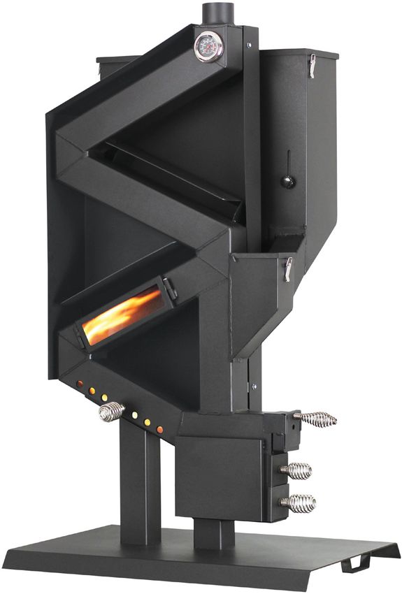
INTRODUCTION
This manual describes the installation and operation of the USSC, GW1949 wood heater. This heater meets the 2020
U.S. Environmental Protection Agency's crib wood emission limits for wood heaters sold after May 15, 2020. Under
specific test conditions this heater has been shown to deliver heat at rates ranging from 9,762 to 38,544 Btu/hr and
0.94 g/hr and 69% efficiency.

Heating Specifications
Estimated Fuel Burn Rate* (lowest setting)     2 lb/hr        * Pellet size may effect the actual rate of fuel feed
Estimated Burn Time (lowest setting)           30 hrs         and burn times. Fuel feed rates may vary by as much
Hopper Capacity                                60 lbs ( 27kg)     as 20%. Use PFI listed fuel for best results.
Dimensions
Overall: Height x Width X Depth                50” (1270 mm) X 24” (610 mm) X 15” (381 mm)
Weight                                         131 lb (59.5 kg)

                                                    WARNING:
IT IS AGAINST FEDERAL REGULATIONS TO OPERATE THIS WOOD HEATER IN A MANNER INCONSISTENT
                 WITH THE OPERATING INSTRUCTIONS IN THE OWNER’S MANUAL.

                     Note: Register your product online at                       For Customer Service, please call:
                     www.usstove.com or download the free                        1-800-750-2723 Ext 5050 or;
                     app today. This app is available only
                                                                                 Text to 423-301-5624 or;
                     on the App Store for iPhone and iPad.
                                                                                 Email us at:
                     Search US Stove. Save your receipt with
                     your records for any claims.                                customerservice@usstove.com

                                                          2
© 2021 United States Stove Company
INSTALLATION CHECKLIST
Your Wood Stove should be installed by a qualified installer only. An NFI qualified Installer can be found at www.
nficertified.org/public/find-an-nfi-pro/

CUSTOMER SERVICE
1-800-750-2723 ext 5050
Text to 423-301-5624
Email to: Customerservice@usstove.com

COMMISSIONING CHECKLIST
This checklist is to be completed in full by the qualified person who installs this unit. Keep this page for future reference.
Failure to install and commission according to the manufacturer’s instructions and complete this checklist will
invalidate the warranty.
                                                                                        Please Print

 Customer Name:                                                                                  Telephone Number:
 Address:
 Model:
 Serial Number:
 Installation Company Name:                                                                      Phone Number:
 Installation Technician’s Name:                                                                 License Number:

DESCRIPTION OF WORK
Location of installed appliance: ___________________________________________________________________________________

Venting System: New Venting System                                     Yes             No If yes, Brand_____________________________________________

If no, Date of inspection of existing venting system:________________________________________________________________

COMMISSIONING
Confirm Hearth Pad Installation as per Installation Instructions....................................................................................................
Confirm proper placement of internal parts...........................................................................................................................................
Check soundness of door gasket and door seals..................................................................................................................................
Confirm clearances to combustibles as per installation instructions in this manual...............................................................
Check the operations of the air controls..................................................................................................................................................
Confirm the venting system is secure and sealed................................................................................................................................
Confirm the stove starts and operates properly...................................................................................................................................
Check to ensure a CO alarm is installed as per local building codes and is functional.............................................................
Explain the safe operation, proper fuel usage, cleaning, and routine maintenance requirements........................................

Declaration of Completion: As the qualified person responsible for the work described above, I confirm that the appliance
as associated work has been installed as per manufacturer’s instructions and following any applicable building and
installation codes.

Signed:_______________________________________ Print Name:___________________________________Date:_______________

Home Owner: RETAIN THIS INFORMATION FOR FUTURE REFERENCE

                                                                                            3
                                                                                                                               © 2021 United States Stove Company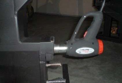
ASSEMBLY INSTRUCTIONS
FOR CUSTOMER SERVICE CALL: 800-750-2723 EXT 5050
TOOLS AND MATERIALS                   go in first. The pellet slide will slide in and seat at the
• One 1/2” opened ended wrench                                  bottom of the feed tube.
• One 7/16” open ended wrench
• One 3/4” socket and ratchet wrench
• Screw gun (cordless is recommended)
• One 5/16” nut driver (extension is recommended)
• One torpedo level
• Needle nose pliers

                        CAUTION:
 THE APPLIANCE IS VERY HEAVY. THE ASSISTANCE                                                            Pellet
 FROM A SECOND PERSON IS STRONGLY                                                                       Slide
 SUGGESTED. PLEASE USE PROPER LIFTING
 TECHNIQUE WHEN POSITIONING THE APPLIANCE                                                             Feed
      FOR ASSEMBLY AND INSTALLATION.                                                                  Tube

MAIN BODY ASSEMBLY
1.   Prepare a solid flat work surface. Lay the main stove
     body on the work surface. Position the stove so that
     the legs are hanging off of the surface approximately
     six inches.
2. Install the base as shown with the two (2) 7/16” hex
   bolts, two (2) flat washers, and two (2) lock washers
   provided with your stove. Note: There is a long end
                                                                DAMPER SLIDE INSTALLATION
   and a short end to the base. To ensure stability of the
                                                                1.   Insert the damper slide into place; it will only fit one
   stove, the long end must face the right side of the
                                                                     way.
   stove.

                                                                                                            Damper
                                                                                                            Slide
PELLET SLIDE INSTALLATION
Install the pellet slide as shown. The chute (flat end) will

                                                               4
 © 2021 United States Stove Company
ASSEMBLY INSTRUCTIONS
2. Screw on the damper slide handle by turning BURN TUBE & ASH TRAY INSTALLATION
clockwise. Install primary burn tube, secondary burn plate, and ash
tray.
Primary
Burn Tube
Secondary
Damper Burn Tube
Slide Ash
Handle Tray
5
© 2021 United States Stove CompanyINSTALLATION
FOR CUSTOMER SERVICE CALL: 800-750-2723 EXT 5050
SAFETY NOTICE CAUTION:
• ALWAYS READ AND FOLLOW THE NEVER USE GASOLINE, GASOLINE TYPE LANTERN
INSTRUCTIONS FOR SAFE USE AND FUEL, KEROSENE, CHARCOAL LIGHTER FLUID, OR
MAINTENANCE OF YOUR STOVE. SIMILAR LIQUIDS TO START UP OR FRESHEN UP
• SURFACES OF THE STOVE GET EXTREMELY A FIRE IN THIS STOVE. KEEP ALL SUCH LIQUIDS
HOT! WELL AWAY FROM THE STOVE WHILE IN USE.
• IF THIS STOVE IS NOT PROPERLY INSTALLED,
A HOUSE FIRE MAY RESULT. TO REDUCE THE
RISK OF FIRE, FOLLOW THE INSTALLATION
INSTRUCTIONS.
• CONTACT YOUR LOCAL BUILDING OFFICIALS TO
OBTAIN A PERMIT AND INFORMATION ON ANY
ADDITIONAL INSTALLATION RESTRICTIONS OR
INSPECTION REQUIREMENTS IN YOUR AREA.
• BE AWARE THAT SURFACES MAY STILL BE HOT
FOR AN EXTENDED PERIOD OF TIME AFTER
THE STOVE HAS BEEN SHUT DOWN. US Stove highly recommends your stove be installed by a
• NEVER LEAVE YOUNG CHILDREN OR PETS qualified NFI (US) or WETT (Canada) technician. To find
AROUND ANY HEATING SOURCE. the nearest qualified installer, go to:
• EDUCATE YOUR FAMILY BEFORE BEGINNING https://nficertified.org,
OPERATION OF YOUR NEW STOVE. https://www.wettinc.ca/
• NEVER BLOCK FREE AIRFLOW THROUGH THE
OPEN VENTS OF THE STOVE. FLOOR PROTECTION
• DO NOT PLACE FLAMMABLE ITEMS ON OR A non-flammable pad must be installed that meets
NEAR ANY STOVE. manufactured floor protector conforms to UL 1618, that
provides at minimum type 1 ember protection.
• NEVER PLACE FOREIGN OBJECTS IN THE
HOPPER.
• THIS STOVE WAS DESIGNED AND APPROVED
FOR PELLETIZED WOOD FUEL ONLY. ANY
OTHER TYPE OF FUEL BURNED IN THIS STOVE
IS PROHIBITED.
• DO NOT CONNECT THIS UNIT TO CHIMNEY
FLUE SERVING ANOTHER APPLIANCE.
• THIS IS A WOOD STOVE THAT BURNS PELLET
FUEL. IT MUST BE TREATED AS A WOOD
STOVE. AS WITH ANY WOOD STOVE PERIODIC
CLEANING AND MAINTENANCE IS REQUIRED.
FAILURE TO CLEAN AND MAINTAIN YOUR REQUIREMENTS OF 3/8” (10 mm) NON-
STOVE AND CHIMNEY MAY RESULT IN POOR COMBUSTIBLE MATERIAL
PERFORMANCE. A Length 31” 787 mm
• ALWAYS ALLOW THE STOVE TO COOL USA 48” 1.22m
COMPLETELY BEFORE PERFORMING ANY B Width
CAN 50” 1.3m
MAINTENANCE.
USA 16” 407 mm
C Right Side
CAN 18” 458 mm
D Left Side 8” 203 mm
E Front 8” 203 mm
6
© 2021 United States Stove CompanyINSTALLATION
CLEARANCE TO COMBUSTIBLES • Existing fuel-fired equipment in the house, such as
fireplaces or other heating appliances, smell, do not
operate properly, suffer smoke roll-out when opened, or
G back-drafts occur whether or not there is combustion
H F present.
F • Opening a window slightly on a calm (windless) day
alleviates any of the above symptoms.
J • The house is equipped with a well-sealed vapor barrier
and tight fitting windows and/or has any powered
Front devices that exhaust house air.
• There is excessive condensation on windows in the
winter.
K
• A ventilation system is installed in the house.
ATTENTION:
F F
DO NOT VENT UNDER ANY PORCH, DECK,
AWNING, OR IN ANY SEMI ENCLOSED OR
ROOFED AREA. DOING SO MAY RESULT IN
UNPREDICTABLE AIRFLOW AT THE VENT CAP
Front UNDER CERTAIN CONDITIONS AND CAN AFFECT
THE PERFORMANCE OF YOUR STOVE, AS WELL
F Left Sidewall to Stove 8” 203 mm AS, OTHER UNFORESEEABLE ISSUES.
G Backwall to Stove 2” 51 mm
H Backwall to Flue* 13-1/2” 343 mm WARNING:
J Sidewall to Flue* 14-1/2” 369 mm DO NOT CONNECT TO OR USE IN CONJUNCTION
K Ceiling Height 36” 915 mm WITH ANY AIR DISTRIBUTION DUCT WORK
UNLESS SPECIFICALLY APPROVED FOR SUCH
INSTALLATION.
OUTSIDE AIR SUPPLY
Adequate ventilation air is required to operate this
Taller or longer chimney system’s may need a barometric
heater. During operation, the heater draws air for
damper installed immediately off the top of the stove
combustion which can be assisted by the installation of
to be able to control the stove down in the 400° range
outside combustion air inlets. However, certain weather
as you can experience excessive draft and the stove will
conditions such as icing or use of kitchen exhaust fans
want to run hotter.
may impact and reduce the effectiveness of vents. It is
important to note that room air starvation will negatively This stove is mobile home approved (U.S.ONLY). Mobile
impact the operation of the heater. Depending on homes require outside air, use a vent with a rigid or flex
your location and home construction, outside air may pipe connected to the stove, and an outside screen vent
be necessary for optimal performance. Your stove is cap. The stove must be secured to the floor, and grounded
approved to be installed with an outside air intake (4FAK) with a number 8 gauge wire. Mobile home installation
which is necessary for a mobile home. You can purchase should be done in accordance with the Manufactured
the 4FAK through your heater dealer. Installation Home and Safety Standard (HUD), CFR 3280, Part 24.
instructions are supplied with the air intake kit. Below Only approved pellet vent can be used. The chimney
is a list of possible indicators that a source of outside installation must allow for removal in case of mobile
combustion air may be required. home transportation, especially outside connections.
You may contact your local building authority or person
• Your stove does not draw steadily, smoke rollout occurs,
having jurisdiction on height restrictions.
wood burns poorly, or back-drafts occur whether or not
there is combustion present.
7
© 2021 United States Stove CompanyINSTALLATION
SECURING APPLIANCE TO THE FLOOR WARNING:
Securely fasten this stove to the floor by screwing 1/4”
DO NOT COMPROMISE INSTRUCTIONS FOR
lag bolts up through the floor into the leg leveling holes.
INSTALLATION OR MAKE CHANGES TO
MANUFACTURERS SPECIFICATIONS DURING THE
WARNING! DO NOT INSTALL IN SLEEPING ROOM. INSTALLATION OF THIS PRODUCT.
CAUTION! THE STRUCTURAL INTEGRITY OF THE
MOBILE HOME FLOOR, WALL, AND CEILING/ Attach and secure the exhaust venting system to the
ROOF MUST BE MAINTAINED. MAINTAIN AN product and to each adjoining section. All joints for
EFFECTIVE VAPOR BARRIER BY SEALING WITH connector pipe shall be required to be fastened with
SILICONE WHERE THE CHIMNEY OR OTHER at least three screws. The area where the vent pipe
COMPONENTS PENETRATE TO THE EXTERIOR OF penetrates to the exterior of the home must be sealed
THE STRUCTURE. with silicone or other means to maintain the vapor barrier
WHEN INSTALLED IN A MOBILE HOME, THE STOVE between the exterior and the interior of the home. Vent
MUST BE GROUNDED DIRECTLY TO THE STEEL surfaces can get hot enough to cause burns if touched.
CHASSIS AND BOLTED TO THE FLOOR. Noncombustible shielding or guards may be required.
In addition to the previously detailed installation IMPORTANCE OF PROPER DRAFT
requirements, mobile home installations must meet the Draft is the force which moves air from the appliance
following requirements: up through the chimney. The amount of draft in your
chimney depends on the length of the chimney, local
• All installations must meet local codes. geography, nearby obstructions and other factors. Too
• Install option 1: Use 3”-4” listed L vent pellet pipe -or- much draft may cause excessive temperatures in the
Install option 2: Use 4”, 5”, or 6” class A 103 HT chimney appliance. Inadequate draft may cause back puffing into
system. Note: Do not mix use of chimney systems the room and ‘plugging’ of the chimney. Inadequate draft
during installation. Use 1 system type throughout the will cause the appliance to leak smoke into the room
installation. through appliance and chimney connector joints. An
• Use a minimum of 24 gauge, 4” or larger connector pipe uncontrollable burn or excessive temperature indicates
with the class A 103 HT chimney system (install option excessive draft. Take into account the chimney’s location
2). to ensure it is not too close to neighbors or in a valley
which may cause unhealthy or nuisance conditions.
• This is a wood stove that burns wood pellet fuel. This
means natural draft is running the stove. It must be STOVE PIPE INSTALLATION
treated as a wood stove with the pipe installation being This stove has no need for electricity, it operates with
as vertical as possible to obtain maximum upward a natural draft. The strength of the draft is determined
draft. by the height of its chimney, and that’s why the chimney
• Horizontal runs and elbows are discouraged. installation is the determining factor on how well this
• Do not install a manual flue damper in the exhaust vent. stove will perform. This stove will operate best with a
straight chimney either 3” diameter or 4” diameter with
Install vent at clearances specified by the vent 8ft to 12ft overall height, although it will operate with
manufacturer. The chimney connector shall not pass many variance’s of chimney height and configurations,
through an attic or roof space, closet or similar concealed they will all bring varied results in burn time and fuel
space, or floor, or ceiling. Where passage through a wall usage. A straight chimney is always the best configuration
or partition of combustible construction is desired, the for this pellet stove. Do not make changes to the draft
installation shall conform to CAN/CSA-B365, US-L recommendations during the installation of the chimney
vent installation code for solid fuel burning appliances or stove. This is a stove that burns pellet fuel, if an adequate
and equipment. Exhaust vent required for residential draft is not accomplished this stove will not operate
installation or mobile home installation (US only) is a properly and can potentially cause smoke to come from
listed type “PL” venting - 3” or 4” (76 mm or 102 mm) the stove. If the draft is compromised, it can drastically
diameter. If installed into a tightly constructed home, impede the performance of the stove, especially when
(Mobile Home) a fresh air opening of at least 2” (150 using hardwood pellet fuel. Long horizontal chimney runs
mm) diameter into the room where the unit is installed will impede the draft and cause poor performance of this
is required. stove.
8
© 2021 United States Stove CompanyINSTALLATION
Install option one: When 8ft to 15ft length of venting is Extended Roof Chimney Cap
Support Bracket
used, utilize 3” diameter listed L vent pellet pipe. When (Conduit not included)
having to use more than 15ft of venting, then utilize a 4” Storm Collar
diameter listed L vent pellet pipe. In some installations Adjustable Roof
Flashing
and because of outside environmental conditions, a
barometric damper may need to be installed immediately
off the top of the stove. This barometric damper will
Attic Insulation Shield
prevent excessive draft which causes your stove to burn
hotter than normal and burn excessive fuel. You can also
Firestop
adjust the bars closer together on the burn basket to Radiation
lower the temperature if it starts running too hot. See the Sheild
Twist-Lock
“Tuning Your Stove” section of this manual. Chimney Sections
A 4” diameter listed L vent pellet pipe is recommended Firesafe
Enclosure
if you decide to go through the wall, and you need to
terminate above the roof at least 24” using pellet vent. Support Box
When installing into an existing chimney, then you must and Trim Collar
Stovepipe with built-in
run 4” vent all the way up any existing chimney and Starter section
terminating at the top.
Install option two: Use minimum 24 gauge single wall TO STOVE
pipe in 4”, 5” or 6” diameter when connecting to listed
factory built chimney. Use a 3”-4”, 3”-5” or 3”-6” increaser
directly off the stove then connect to the required length
of pipe to reach the factory built chimney. A slip joint can
be used to allow connection to the factory built chimney
or a plug can be inserted at the entry point of the factory
IMPORTANT:
built chimney. The connector pipe shall pass through
the plug a minimum of 4” or can pass through the entire IT IS IMPORTANT FOR THE STOVE PIPE TO EXTEND
length of the chimney. When using this method install TO AT LEAST AS HIGH AS THE HIGHEST POINT OF
another properly sized plug at the top of the chimney and YOUR ROOF.
continue connector pipe out and above the plug at least
2”. Install proper sized cap or in the event factory built Any reduction in clearance to combustibles may only be
cap is already in place with spark arrester, the connector done by means approved by a regulatory authority. Install
pipe can be terminated under the existing factory built vent at clearances specified by the vent manufacturer.
cap. When installing your stove, an all vertical stove pipe,
straight up and through the roof is best. This will ensure COMBUSTIBLE WALL CHIMNEY
a good upward draft that all stoves need to operate. The CONNECTOR PASS-THROUGHS
more twists and turns you have in stove piping the more Method A. 12” (305 mm) Clearance to Combustible
it will restrict the draft. This is true for all stoves. Wall Member: Using a minimum thickness 3.5” (89 mm)
brick and a 5/8” (16 mm) minimum wall thickness clay
liner, construct a wall pass-through. The clay liner must
conform to ASTM C315 (Standard Specification for
Clay Fire Linings) or its equivalent. Keep a minimum of
12” (305 mm) of brick masonry between the clay liner
and wall combustibles. The clay liner shall run from the
brick masonry outer surface to the inner surface of the
chimney flue liner but not past the inner surface. Firmly
grout or cement the clay liner in place to the chimney flue
liner.
9
© 2021 United States Stove CompanyINSTALLATION
to fit and hold the metal chimney connector. See that
the supports are fastened securely to wall surfaces on
all sides. Make sure fasteners used to secure the metal
chimney connector do not penetrate chimney flue liner.
Method B. 9” (229 mm) Clearance to Combustible Wall
Member: Using a 6” (153 mm) inside diameter, listed,
factory-built Solid-Pak chimney section with insulation
of 1” (26 mm) or more, build a wall pass-through with a
minimum 9” (229 mm) air space between the outer wall
Method D. 2” (51 mm) Clearance to Combustible Wall
of the chimney length and wall combustibles. Use sheet
Member: Start with a solid-pak listed factory built
metal supports fastened securely to wall surfaces on
chimney section at least 12” (304 mm) long, with
all sides, to maintain the 9” (229 mm) air space. When
insulation of 1” (26 mm) or more, and an inside diameter
fastening supports to chimney length, do not penetrate
of 8” (2 inches [51 mm] larger than the 6” [153 mm]
the chimney liner (the inside wall of the Solid-Pak
chimney connector). Use this as a pass-through for a
chimney). The inner end of the Solid-Pak chimney section
minimum 24-gauge single wall steel chimney connector.
shall be flush with the inside of the code-approved
Keep solid-pak section concentric with and spaced 1” (26
masonry chimney with a flue liner flue, and sealed with a
mm) off the chimney connector by way of sheet metal
non-water soluble refractory cement. Use this cement to
support plates at both ends of chimney section. Cover
also seal to the brick masonry penetration.
opening with and support chimney section on both sides
with 24 gauge minimum sheet metal supports. See that
the supports are fastened securely to wall surfaces on all
sides. Make sure fasteners used to secure chimney flue
do not penetrate flue liner.
Method C. 6” (153 mm) Clearance to Combustible Wall
Member: Starting with a minimum 24 gauge (.024”
[.61 mm]) 6” (153 mm) metal chimney connector, and
a minimum 24 gauge ventilated wall thimble which has
two air channels of 1” (26 mm) each, construct a wall NOTES: Connectors to a code-approved masonry
pass-through. There shall be a minimum 6” (153 mm) chimney with a flue liner, excepting method B, shall
separation area containing fiberglass insulation, from the extend in one continuous section through the wall pass-
outer surface of the wall thimble to wall combustibles. through system and the chimney wall, to but not past the
Support the wall thimble, and cover its opening with a inner flue liner face. A chimney connector shall not pass
24-gauge minimum sheet metal support. Maintain the through an attic or roof space, closet or similar concealed
6” (153 mm) space. There should also be a support sized space, or a floor, or ceiling.
10
© 2021 United States Stove CompanyOPERATION INSTRUCTIONS
NEVER OPERATE THIS PRODUCT WHILE UNATTENDED
WARNING: Your pellet stove is designed to burn premium hardwood
pellets that comply with the Pellet Fuels Institute (PFI)
• DO NOT USE CHEMICALS OR FLUIDS TO START
standard (minimum of 40 lbs density per cubic ft, 1/4” to
THE FIRE - NEVER USE GASOLINE, GASOLINE-
5/16” diameter, length no greater than 1.5”, not less than
TYPE LANTERN FUEL, KEROSENE, CHARCOAL
8,200 BTU/lb, moisture under 8% by weight, ash under
LIGHTER FLUID, OR SIMILAR LIQUIDS TO START
1% by weight, and salt under 300 parts per million).
OR “FRESHEN UP” A FIRE IN THIS STOVE. KEEP
Pellets that are soft, contain excessive amounts of loose
ALL SUCH LIQUIDS WELL AWAY FROM THE
sawdust, have been, or are wet, will result in reduced
STOVE WHILE IT IS IN USE.
performance. Store your pellets in a dry place. DO NOT
• HOT WHILE IN OPERATION. KEEP CHILDREN, store the fuel within the installation clearances of the
CLOTHING AND FURNITURE AWAY. CONTACT unit or within the space required for charging and ash
MAY CAUSE SKIN BURNS. removal. Doing so could result in a house fire. Do not over
fire or use volatile fuels or combustibles, doing so may
This heater is designed to burn only PFI Premium grade cause a personal and property damage hazards.
pellets. DO NOT BURN: THIS STOVE IS APPROVED FOR BURNING PELLETIZED
1. Garbage; WOOD FUEL ONLY ! Factory-approved pellets are those
1/4” or 5/16” in diameter and not over 1” long. Burning
2. Lawn clippings or yard waste;
wood in forms other than pellets is not permitted. It
3. Materials containing rubber, including tires; will violate the building codes for which the stove has
4. Materials containing plastic; been approved and will void all warranties. The design
incorporates automatic feed of the pellet fuel into the
5. Waste petroleum products, paints or paint thinners,
fire at a carefully prescribed rate. Any additional fuel
or asphalt products;
introduced by hand will not increase heat output but may
6. Materials containing asbestos; seriously impair the stoves performance by generating
7. Construction or demolition debris; considerable smoke. Do not burn wet pellets. The
stove’s performance depends heavily on the quality of
8. Railroad ties or pressure-treated wood;
your pellet fuel. Avoid pellet brands that display these
9. Manure or animal remains; characteristics:
10. Salt water driftwood or other previously salt water • Excess Fines – “Fines” is a term describing crushed
saturated materials; pellets or loose material that looks like sawdust or sand.
11. Unseasoned wood; or Pellets can be screened before being placed in hopper
to remove most fines.
12. Paper products, cardboard, plywood, or particleboard.
The prohibition against burning these materials does • Binders – Some pellets are produced with materials to
not prohibit the use of fire starters made from paper, hold the together, or “bind” them.
cardboard, saw dust, wax and similar substances • High ash content – Poor quality pellets will often create
for the purpose of starting a fire in an affected wood smoke and dirty glass. They will create a need for more
heater. frequent maintenance. You will have to empty the burn
Burning these materials may result in release of toxic pot plus vacuum the entire system more often.
fumes or render the heater ineffective and cause smoke.
CAUTION:
PROPER FUEL • KEEP FOREIGN OBJECTS OUT OF THE HOPPER.
• DO NOT BLOCK THE FRESH AIR INTAKE
ATTENTION:
PORTS – THIS WILL SERIOUSLY AFFECT THE
THIS APPLIANCE IS DESIGNED FOR THE USE OF PERFORMANCE OF THE STOVE.
PELLETIZED FUEL THAT MEET OR EXCEED THE
STANDARD SET BY THE PELLET FUEL INSTITUTE
(PFI).
11
© 2021 United States Stove CompanyOPERATION INSTRUCTIONS
WARNING:
ATTEMPTS TO ACHIEVE HEAT OUTPUT RATES
THAT EXCEED HEATER DESIGN SPECIFICATIONS
CAN RESULT IN PERMANENT DAMAGE TO THE
HEATER.
LIGHTING WITH A HANDHELD PROPANE
TORCH
You will need a handheld propane torch to ignite your
stove. We recommend a high quality torch with a squeeze
trigger ignition system.
1. Make sure the pellet feed door is in the closed
position, this is the external knob located on the front
of the hopper. All the way down indicates closed.
2. Remove hopper lid and add desired amount of pellets.
3. Make sure front damper slide is in the closed position, Feed Door
holes should be blocked. (in the closed
position)
4. Inspect primary burn chamber, secondary burn plate
and ashtray for soot build up and cleanliness. Perform
any maintenance required.
5. Reinstall primary burn chamber, secondary burn
plate and ashtray.
Primary Chamber
6. Remove the primary chamber end slide (the top End Slide
handle).
7. Light the torch and insert into primary burn chamber.
Let the torch run for approximately one minute. This
will start the necessary draft and speed the ignition Secondary
Damper Slide Burn Plate
process. Closed (holes
Ash Tray
8. Slide the feed to the all the way open position (the blocked)
knob should now be at the top of the slot).
9. Let the torch run till the stove reaches 200 degrees
(this should only take approximately 5 minutes
depending on the type of fuel).
10. Remove, turn off and store your torch.
LIGHTING WITH A HEAT GUN
11. Keep the primary slide cover off until the stove
You will need a 120 volt industrial heat gun available at
reaches approximately 400°F.
most hardware stores.
1. Follow steps 1-6 of the lighting with a handheld
WARNING:
propane torch instruction.
AFTER STARTING THE STOVE THE PRIMARY END
2. Plug in and turn on heat gun to the high setting then
SLIDE MUST BE ON TO ENSURE PROPER AIR FLOW
insert heat gun.
THROUGH THE SECONDARY BURN CHAMBER AND
PROPER USE OF OUTSIDE AIR. 3. Let heat gun run for 30 seconds.
4. Open the pellet feed door.
5. Ignition of the pellets will take approximately one
minute. You will hear a “whoosh” when the pellets
ignite.
12
© 2021 United States Stove CompanyOPERATION INSTRUCTIONS
6. Turn heat gun down to the low setting and continue CAUTION:
to run until the stove reaches 400 degrees, this will
DO NOT OVER LOOSEN THE DAMPER SLIDE
happen rapidly after ignition of the pellets.
HANDLE! THIS MAY CAUSE THE HANDLE TO
7. Remove, turn off and store your heat gun. SEPARATE FROM THE DAMPER PLATE.
8. Reinstall the primary chamber end slide.
TUNING YOUR STOVE
After your stove is installed and ready for use there will
be a period of time where some adjustments may be
necessary to fit your specific needs from the stove. We
like to refer to this as “getting to know your stove”. Each
stove demonstrates its own unique personality based
upon; type of pellet fuel, elevation, square footage you are
heating, barometric pressures, common wind currents,
natural drafts within your home to name a few. Specifically
this means learning how often you will need to dump
ashes, clear the secondary burn plate, experiment with
CONTROLLING THE TEMPERATURE different brand pellets and determining what position the
damper slide needs to be in to get your specific desired
results. After you have become familiar with the stove
it is possible that you may need to adjust the primary
burn basket. The primary burn basket that comes with
every stove is sent out at a preset measurement. This
measurement fits most applications but sometimes a
user will need to make an adjustment. This is simple to
perform; we find the best tools for widening the basket
are two chisels. For narrowing the spacing use a pair of
pliers. The three black arrows indicate the three spaces
where pellets drop through the basket and on to the
secondary burn plate. The minimum spacing should not
be adjusted to less than 0.290, or on a tape measure the
closest mark would be just under the 19/64”mark.
OPEN
Because the damper slide is located behind the
combustion chamber, adjusting the temperature is
the opposite of a traditional wood stove. To adjust the
damper slide: turn handle counter clockwise one half turn
then slide to the desired position and retighten. The open
position will reduce the draft and slow the stove down
much like a crack in a drinking straw. Closing the damper The maximum adjustment should not exceed 0.320, or
will increase higher temperatures and heat output. just over the 5/16” mark on a tape measure. Only make
small adjustments at a time as you will discover a small
13
© 2021 United States Stove CompanyOPERATION INSTRUCTIONS
adjustment can result in a drastic temperature change. as described in this manual. If this does not bring the
Narrowing will slow the pellet feed rate resulting in lower temperature back up then close the pellet stop plate for
running temperature. Widening will result in an increased approximately 35 minutes running the stove on high.
pellet feed rate resulting in a higher running temperature. Reopen the pellet stop plate. This clears the vertical
feed tube of any pre-heated pellets and reintroduces
HELPFUL HINTS fresh pellet fuel.
• Starting the draft by letting the handheld torch run
for one minute before introducing pellets is highly REFUELLING
recommended. When the stove is cold and it is colder
outside than it is inside, there is a downward draft in CAUTION:
the chimney. Running the torch for one minute first will • THE HOPPER AND STOVE WILL BE HOT
overcome this downward draft that is present. DURING OPERATION; THEREFORE, YOU
• If smoke becomes present during ignition, reposition SHOULD ALWAYS USE SOME TYPE OF HAND
the torch head so the flame is burning across the PROTECTION WHEN REFUELING YOUR STOVE.
bottom of the burn basket not directly on it. • DO NOT TOUCH THE HOT SURFACES OF THE
• The secondary burn plate can be slid out up to one inch STOVE. EDUCATE ALL CHILDREN ON THE
to provide maximum airflow during operation. DANGERS OF A HIGH-TEMPERATURE STOVE.
YOUNG CHILDREN SHOULD BE SUPERVISED
• While operating the stove on low (damper holes open)
WHEN THEY ARE IN THE SAME ROOM AS THE
the temperature gauge should never fall below 300°.
STOVE.
Two things happen when the stove falls below 300°.
1) The draft will slow down enough to impede the • WE RECOMMEND THAT YOU NOT LET THE
performance of the stove. 2) Creosote will build up HOPPER DROP BELOW 1/4 FULL.
causing poor performance and increase the risk of a
flue fire. WARNING:
• If it was necessary to adjust the primary burn basket • KEEP HOPPER LID CLOSED AT ALL TIMES
wider, it may be necessary to clear the secondary burn EXCEPT WHEN REFILLING.
plate more often during operation.
• DO NOT OVERFILL HOPPER.
• A barometric damper will help solve problems when
the stove is experiencing constant high heat output.
Barometric gives the user the ability to regulate draft TAMPER WARNING
through the chimney until desired temperatures are This wood heater has a manufacturer-set minimum
established on the appliance it has been installed on. burn rate that must not be altered. It is against federal
regulations to alter this setting or otherwise operate this
• A VacuStack chimney cap is recommended when wood heater in a manner inconsistent with operating
experiencing draft issues or fluctuating temperatures instructions in this manual.
or low heat output. VacuStack caps are designed to
increase draft on any chimney by causing a vacuum
SHUTTING DOWN THE STOVE
effect through the flue below when the air moves past
When you are ready to shut your stove down simply
the cap.
close the pellet feed door (move to the down position).
• CAUTION: In high wind areas, excessive draft can be After you have closed the pellet feed door the stove will
experienced resulting in extended high-temperature continue to run for approximately 45 minutes. When
output on the stove. We recommend a barometric shutting down the stove make sure to close the draft slide
damper be installed when this occurs which gives you (holes blocked).
the ability to control the excessive draft created by the
vacustack and persistent wind currents above.
• Remedies for those that experience a temperature
drop after several hours of operation: First, dump the
ashtray and properly dispose of ashes as described in
this manual. Second, clear the secondary burn plate
14
© 2021 United States Stove CompanyMAINTENANCE
NEVER OPERATE THIS PRODUCT WHILE UNATTENDED
CAUTION: 4. Remove the burn pot and vacuum out the burn pot
chamber.
• FAILURE TO CLEAN AND MAINTAIN THIS
UNIT AS INDICATED CAN RESULT IN POOR
PERFORMANCE, SAFETY HAZARDS, FIRE, AND
EVEN DEATH.
• NEVER PERFORM ANY INSPECTIONS,
CLEANING, OR MAINTENANCE ON A HOT
STOVE.
• DO NOT OPERATE STOVE WITH BROKEN GLASS,
LEAKAGE OF FLUE GAS MAY RESULT.
CLEANING
Learn your stove! This stove has no moving parts and
requires no electricity; it does however require your
attention much like a wood stove, especially when burning
a hardwood pellet. It is very important to thoroughly clean
the fly ash out of this unit weekly. The window will need
to be remove to properly clean the fly ash out of the unit.
Steps for removing the fly ash are as listed:
1. Allow the unit to cool completely. Remove the 5/16”
diameter pin on the right side of the window as shown
2. Lift up on the window frame to disengage the left side
of the window as shown. Note: When removing the 5. When finished cleaning the ashes reinstall the
window be very careful to hold both the glass and the window and burn pot.
frame.
6. CLEARING YOUR SECONDARY BURN PLATE IS A
MUST WHILE BURNING HARDWOOD PELLETS.
First, remove the ashtray and dispose of any ashes as
previously described, and reinstall ashtray. Second,
remove secondary burn plate. This will allow any built
up ashes and hot coals to fall into the ashtray. Inspect
the secondary burn plate, any layers of ash should be
removed and discarded. Lightly tap the secondary
burn plate on the edge of your disposal container
to clear any clogged hole(s) in the burn plate. This
will resume proper air flow through the burn plate;
3. Vacuum the cooled ash out of the unit. Be sure to reinstall the secondary burn plate.
vacuum both upstream and downstream of the
Considering the numerous different fuels and
window opening. Note: All vacuuming must be
installations, there is no one formula for how often this
performed using an ash vac.
needs to be performed. Letting the secondary burn
plate build up with ashes can choke the stove causing a
decrease in temperature and increase the possibility of
smouldering fuel and smoke. Until experience has helped
you establish a regular routine it is not recommended
to leave the stove unattended for long periods of time.
ALWAYS EMPTY THE ASHTRAY AND CLEAR THE
SECONDARY BURN PLATE PRIOR TO LEAVING THE
STOVE UNATTENDED!
15
© 2021 United States Stove CompanyMAINTENANCE
CREOSOTE FORMATION, INSPECTION, & Ashes should be placed in a steel container with a tight
REMOVAL fitting lid. The closed container of ashes should be placed
on a noncombustible floor or on the ground, well away
CAUTION: from all combustible materials, pending final disposal. If
THE EXHAUST SYSTEM SHOULD BE CHECKED the ashes are disposed of by burial in soil or otherwise
MONTHLY DURING THE BURNING SEASON FOR locally dispersed, they should be retained in the closed
ANY BUILD-UP OF SOOT OR CREOSOTE. container until all cinders have been thoroughly cooled.
SMOKE AND CO MONITORS
When any wood is burned slowly, it produces tar and Burning wood naturally produces smoke and carbon
other organic vapors, which combine with expelled monoxide(CO) emissions. CO is a poisonous gas when
moisture to form creosote. The creosote vapors condense exposed to elevated concentrations for extended
in the relatively cool chimney flue or a newly started periods of time. While the modern combustion systems
fire or from a slow-burning fire. As a result, creosote in heaters drastically reduce the amount of CO emitted
residue accumulates on the flue lining. When ignited, this out the chimney, exposure to the gases in closed or
creosote makes an extremely hot fire, which may damage confined areas can be dangerous. Make sure you stove
the chimney or even destroy the house. Despite their high gaskets and chimney joints are in good working order
efficiency, pellet stoves can accumulate creosote under and sealing properly to ensure unintended exposure. It is
certain conditions. The chimney connector and chimney recommended that you use both smoke and CO monitors
should be inspected by a qualified person annually or per in areas having the potential to generate CO. A working
ton of pellets to determine if a creosote or fly ash build- smoke detector must be installed in the same room as
up has occurred. If creosote has accumulated, it should this product. Install a smoke detector on each floor of
be removed to reduce the risk of a chimney fire. Inspect your home; incase of accidental fire from any cause it
the system at the stove connection and at the chimney can provide time for escape. The smoke detector must be
top. Cooler surfaces tend to build creosote deposits installed at least 15 feet (4,57 M) from the appliance in
quicker, so it is important to check the chimney from order to prevent undue triggering of the detector when
the top as well as from the bottom. The creosote should reloading.
be removed with a brush specifically designed for the
type of chimney in use. A qualified chimney sweep can CHECK & CLEAN THE HOPPER
perform this service. It is also recommended that before Check the hopper periodically to determine if there is any
each heating season the entire system be professionally sawdust (fines) that is building up in the feed system or
inspected, cleaned and, if necessary, repaired. To clean pellets that are sticking to the hopper surface. Clean as
the chimney, disconnect the vent from the stove. needed.
FLY ASH DOOR AND GLASS GASKETS
This accumulates in the horizontal portion of an exhaust Inspect the door and glass window gaskets periodically.
run. Though non-combustible, it may impede the normal The door may need to be removed to have frayed, broken,
exhaust flow. It should therefore be periodically removed. or compacted gaskets replaced by your authorized dealer.
This unit’s door uses a 0.125 x 1” flat gasket. Inspect and
ASH REMOVAL & DISPOSAL clean the secondary burn plate, primary burn basket,
primary burn tube and ashtray prior to igniting the stove.
CAUTION: Do not operate your stove with the viewing door open,
ALLOW THE STOVE TO COOL BEFORE PERFORMING safety concern may arise. The feed door must be closed
ANY MAINTENANCE OR CLEANING. ASHES and sealed during operation.
MUST BE DISPOSED OF IN A METAL CONTAINER
WITH A TIGHT FITTING LID. THE CLOSED PAINTED SURFACES
CONTAINER OF ASHES SHOULD BE PLACED ON It is highly recommended that the initial burn of your new
A NON-COMBUSTIBLE SURFACE OR ON THE stove be done outdoors. The paint used to coat your stove
GROUND, WELL AWAY FROM ALL COMBUSTIBLE a high temperature paint that is dry upon arrival but has
MATERIALS, PENDING FINAL DISPOSAL. a final cure that happens during the initial burn. This
cure will last 20-30 minutes and will produce fumes and
some smoke.
16
© 2021 United States Stove CompanyMAINTENANCE
GLASS SPRING SHUTDOWN
We recommend using a high quality glass cleaner. Should After the last burn in the spring, remove any remaining
a buildup of creosote or carbon accumulate, you may wish pellets from the hopper. Scoop out the pellets. Vacuum
to use 000 steel wool and water to clean the glass. DO out the hopper. Thoroughly clean the burn pot, and
NOT use abrasive cleaners. DO NOT perform the cleaning firebox. It may be desirable to spray the inside of the
while the glass is HOT. Do not attempt to operate the unit cleaned hopper with an aerosol silicone spray if your
with broken glass. Replacement glass may be purchased stove is in a high humidity area. The exhaust system
from your U.S. Stove dealer. If glass is broken, follow should be thoroughly cleaned.
these removal procedures:
1. Remove the hinge pin located on the right side of the ATTENTION:
window frame by pushing the pin-up and out. THIS WOOD HEATER NEEDS PERIODIC INSPECTION
2. The window frame will now swing open. Use caution AND REPAIR FOR PROPER OPERATION. IT IS
as glass will now be loose. Perform necessary cleaning AGAINST FEDERAL REGULATIONS TO OPERATE
and reinstall. NOTE: There are cleaning products THIS WOOD HEATER IN A MANNER INCONSISTENT
available at your local stove dealer specifically for WITH OPERATING INSTRUCTIONS IN THIS
cleaning stove glass. MANUAL.
DO NOT USE SUBSTITUTE MATERIALS WHEN
REPLACING GLASS.
MAINTENANCE SCHEDULE
DO NOT abuse the door glass by striking, slamming, or Establish a routine for the fuel, the burner, and the
similar trauma. Do not operate the stove with the glass firing technique. Check daily for creosote build-up until
removed, cracked, or broken. experience shows how often cleaning is needed to be safe.
Be aware, hotter the fire the less creosote is deposited
FALL START UP so weekly cleaning may be necessary during colder
Prior to starting the first fire of the heating season, weather; however, monthly cleaning may be enough
check the outside area around the exhaust and air intake during warmer months. NOTE: Failure to keep a clean
systems for obstructions. Clean and remove any fly ash burn chamber or secondary burn plate can result in poor
from the exhaust venting system. Clean any screens on stove performance. NOTE: Letting ash build up into the
the exhaust system and on the outside air intake pipe. primary burn basket can cause choking of the stove and
This is also a good time to give the entire stove a good increase the risk of smoldering fuel and or smoke spillage.
cleaning throughout.
HOW TO ORDER REPAIR PARTS
For Parts Assistance Call: 800-750-2723 Ext 5051 or Email: parts@usstove.com
The information in this owner’s manual is specific to your unit. When ordering replacement parts the information
in this manual will help to ensure the correct items are ordered. Before contacting customer service write down the
model number and the serial number of this unit. That information can be found on the certification label attached
to the back of the unit. Other information that may be needed would be the part number and part description of the
item(s) in question. Part numbers and descriptions can be found in the “Repair Parts” section of this manual. Once
this information has been gathered you can contact customer service by phone 1-800-750-2723 Ext 5051 or Email
parts@usstove.com.
Model Information
Model Number
Serial Number
17
© 2021 United States Stove CompanyREPAIR PARTS
1
2
3
26
4
5
8
25
9
10 6
11 12
13
7
14
22
23
24
16 15
21
17
18
19
20
18
© 2021 United States Stove CompanyREPAIR PARTS
Key Part # Description Qty
1 610473 Hinged Top Assembly 1
2 88174 Gasket, Window .125 X 1” W/Psa 4.8 ft
3 610329 Hopper 1
4 610202 Pellet Stop 1
5 83936 1/4-20 Plastic Knob 1
6 88174 Gasket - Flat, Glass (3/16T x 3/8W) 16”
7 610442 Heat Shield 1
8 27774 Feed Lid 1
9 88174 Gasket - Flat, Glass (3/16T X 3/8W) 1”
10 27775 Hinge Rod 1
11 892222 Latch, Hopper Lid 3
12 27428 Pellet Slide 1
13 610192 Burn Chamber 1
14 610200 Firebox 1
15 610208 Weldment, Air Cover Handle 1
16 27445 Air Cover 1
17 610189 Handle Weldment 3
18 610210 Burn Plate Assembly 1
19 610187 Ash Pan 1
20 610474 Pedestal 1
21 610204 Draft Slide 1
22 892553 GW1949 Glass 1
23 88087 Gasket, Window .125 x 1” w/PSA 2 ft
24 610205 Window Frame 1
25 83671 5/16 Dia Pin 1
26 80653 Thermometer 1
To order parts:
Call 1-800-750-2723 Ext 5051 or
Email to: parts@usstove.com
IN ORDER TO MAINTAIN WARRANTY, COMPONENTS MUST BE REPLACED USING ORIGINAL USSC PARTS
PURCHASED THROUGH YOUR DEALER OR DIRECTLY FROM USSC. USE OF THIRD PARTY COMPONENTS
WILL VOID THE WARRANTY.
19
© 2021 United States Stove CompanySERVICE RECORD
It is recommended that your heating system is serviced regularly and that the appropriate Service Interval Record is
completed.
SERVICE PROVIDER
Before completing the appropriate Service Record below, please ensure you have carried out the service as described in
the manufacturer’s instructions. Always use the manufacturer's specified spare part when replacement is necessary.
Service 01 Date:_______________________ Service 02 Date:_______________________
Engineer Name:_____________________________________ Engineer Name:_____________________________________
License No.:_________________________________________ License No.:_________________________________________
Company:___________________________________________ Company:___________________________________________
Telephone No.:______________________________________ Telephone No.:______________________________________
Stove Inspected: Chimney Swept: Stove Inspected: Chimney Swept:
Items Replaced:_____________________________________ Items Replaced:_____________________________________
Service 03 Date:_______________________ Service 04 Date:_______________________
Engineer Name:_____________________________________ Engineer Name:_____________________________________
License No.:_________________________________________ License No.:_________________________________________
Company:___________________________________________ Company:___________________________________________
Telephone No.:______________________________________ Telephone No.:______________________________________
Stove Inspected: Chimney Swept: Stove Inspected: Chimney Swept:
Items Replaced:_____________________________________ Items Replaced:_____________________________________
Service 05 Date:_______________________ Service 06 Date:_______________________
Engineer Name:_____________________________________ Engineer Name:_____________________________________
License No.:_________________________________________ License No.:_________________________________________
Company:___________________________________________ Company:___________________________________________
Telephone No.:______________________________________ Telephone No.:______________________________________
Stove Inspected: Chimney Swept: Stove Inspected: Chimney Swept:
Items Replaced:_____________________________________ Items Replaced:_____________________________________
Service 07 Date:_______________________ Service 08 Date:_______________________
Engineer Name:_____________________________________ Engineer Name:_____________________________________
License No.:_________________________________________ License No.:_________________________________________
Company:___________________________________________ Company:___________________________________________
Telephone No.:______________________________________ Telephone No.:______________________________________
Stove Inspected: Chimney Swept: Stove Inspected: Chimney Swept:
Items Replaced:_____________________________________ Items Replaced:_____________________________________
20
© 2021 United States Stove CompanyENREGISTREMENT DE SERVICE
Il est recommandé que votre système de chauffage est desservi régulièrement et que le Service Interval enregistrement approprié
est terminée.
FOURNISSEUR DE SERVICES
Avant de terminer l’enregistrement de service approprié ci-dessous, s’il vous plaît vous assurer que vous avez effectué le service tel
que décrit dans le les instructions du fabricant. Toujours utiliser pièce de rechange indiquée par le fabricant lors de remplacement
est nécessaire.
Service de 01 Date: ______________________ Service de 02 Date: ______________________
Nom de l’ingénieur: _________________________________ Nom de l’ingénieur: _________________________________
N° de licence.: ______________________________________ N° de licence.: ______________________________________
Compagnie: ________________________________________ Compagnie: ________________________________________
N° de téléphone: ___________________________________ N° de téléphone: ___________________________________
Poêle Inspecté: Cheminée balayée: Poêle Inspecté: Cheminée balayée:
Articles Remplacé: _________________________________ Articles Remplacé: _________________________________
Service de 03 Date: ______________________ Service de 04 Date: ______________________
Nom de l’ingénieur: _________________________________ Nom de l’ingénieur: _________________________________
N° de licence.: ______________________________________ N° de licence.: ______________________________________
Compagnie: ________________________________________ Compagnie: ________________________________________
N° de téléphone: ___________________________________ N° de téléphone: ___________________________________
Poêle Inspecté: Cheminée balayée: Poêle Inspecté: Cheminée balayée:
Articles Remplacé: _________________________________ Articles Remplacé: _________________________________
Service de 05 Date: ______________________ Service de 06 Date: ______________________
Nom de l’ingénieur: _________________________________ Nom de l’ingénieur: _________________________________
N° de licence.: ______________________________________ N° de licence.: ______________________________________
Compagnie: ________________________________________ Compagnie: ________________________________________
N° de téléphone: ___________________________________ N° de téléphone: ___________________________________
Poêle Inspecté: Cheminée balayée: Poêle Inspecté: Cheminée balayée:
Articles Remplacé: _________________________________ Articles Remplacé: _________________________________
Service de 07 Date: ______________________ Service de 08 Date: ______________________
Nom de l’ingénieur: _________________________________ Nom de l’ingénieur: _________________________________
N° de licence.: ______________________________________ N° de licence.: ______________________________________
Compagnie: ________________________________________ Compagnie: ________________________________________
N° de téléphone: ___________________________________ N° de téléphone: ___________________________________
Poêle Inspecté: Cheminée balayée: Poêle Inspecté: Cheminée balayée:
Articles Remplacé: _________________________________ Articles Remplacé: _________________________________
20
© 2021 United States Stove CompanySCHÉMA DES PIÈCES
Clé Partie # Description Qté
1 610473 Ensemble Supérieur Articulé 1
2 88174 Joint, Fenêtre, 0,125 X 1 Po Avec/Psa 4,8 pi
3 610329 Trémie 1
4 610202 Arrêt Des Granules 1
5 83936 Bouton En Plastique 1/4-20 1
6 88174 Joint - Plat, Vitre (3/16 T X 3/8 W) 16 po
7 610442 Écran Thermique 1
8 27774 Couvercle De L'alimentation 1
9 88174 Joint - Plat, Vitre (3/16 T X 3/8 W) 15 po
10 27775 Tige De La Charnière 1
11 892222 Loquet, Couvercle De La Trémie 3
12 27428 Glissière À Granules 1
13 610192 Chambre À Combustion 1
14 610200 Boîte À Combustion 1
15 610208 Assemblage Soudé, Poignée Du Couvercle À Air 1
16 27445 Couvercle À Air 1
17 610189 Assemblage Soudé De La Poignée 3
18 610210 Assemblage De La Plaque De Combustion 1
19 610187 Tiroir À Cendres 1
20 610474 Piédestal 1
21 610204 Glissière Du Tirage D'air 1
22 892553 Vitre GW1949 1
23 88087 Joint, Fenêtre, 0,125 X 1 Po Avec/Psa 2 pi
24 610205 Cadre De La Fenêtre 1
25 83671 Goupille De 5/16 De Diamètre 1
26 80653 Thermomètre 1
Pour commander des pièces:
Appelez le 1-800-750-2723 Ext 5051 ou
Envoyez un courriel à: parts@usstove.com
AFIN DE MAINTENIR LA GARANTIE, LES COMPOSANTS DOIVENT ÊTRE REMPLACÉS À L’AIDE DES PIÈCES ORIGINALES
DU FABRICANT ACHETÉES PAR L’INTERMÉDIAIRE DE VOTRE REVENDEUR OU DIRECTEMENT AUPRÈS DU FABRICANT
DE L’APPAREIL. L’UTILISATION DE COMPOSANTS TIERS ANNULERA LA GARANTIE.
19
© 2021 United States Stove CompanyYou can also read