N65 Wood Stove Installation & Operation Instruction Manual
←
→
Page content transcription
If your browser does not render page correctly, please read the page content below

N65 Wood Stove
Installation & Operation Instruction Manual

THE N65 WOOD STOVE HAS BEEN TESTED FOR EMISSIONS AND
EFFICIENCY AND CERTIFIED TO US ENVIRONMENTAL PROTECTION
AGENCY’S PHASE II 2020 CORD WOOD STANDARD. ALSO, N65 HAS
BEEN TESTED AND COMPLIES TO ULC S627 & UL 1482-2011 (R2015)
SAFETY STANDARDS BY AN ACCREDITED LABORATORY.

       Report # 0568WS001E
       Report # 0568WS001S                                    7216160100R01
Table of Contents
Welcome & Congratulations . . . . . . . . . . . . . . . . . . . . . . . . . . . . . . . . . . . . . . . . . . . . . . . . . . . . . . . 2
CAUTIONS & WARNINGS . . . . . . . . . . . . . . . . . . . . . . . . . . . . . . . . . . . . . . . . . . . . . . . . . . . . . . . 3
Safety Label. . . . . . . . . . . . . . . . . . . . . . . . . . . . . . . . . . . . . . . . . . . . . . . . . . . . . . . . . . . . . . . . . . . . 4
Performance . . . . . . . . . . . . . . . . . . . . . . . . . . . . . . . . . . . . . . . . . . . . . . . . . . . . . . . . . . . . . . . . . . . 5
Specifications. . . . . . . . . . . . . . . . . . . . . . . . . . . . . . . . . . . . . . . . . . . . . . . . . . . . . . . . . . . . . . . . . . . 6
Installation . . . . . . . . . . . . . . . . . . . . . . . . . . . . . . . . . . . . . . . . . . . . . . . . . . . . . . . . . . . . . . . . . . . . . 7
     Components. . . . . . . . . . . . . . . . . . . . . . . . . . . . . . . . . . . . . . . . . . . . . . . . . . . . . . . . . . . . . . . . 7
     Assembling the Stove. . . . . . . . . . . . . . . . . . . . . . . . . . . . . . . . . . . . . . . . . . . . . . . . . . . . . . . . . 7
     Positioning the Stove . . . . . . . . . . . . . . . . . . . . . . . . . . . . . . . . . . . . . . . . . . . . . . . . . . . . . . . . . 7
     Outside Air Requirements. . . . . . . . . . . . . . . . . . . . . . . . . . . . . . . . . . . . . . . . . . . . . . . . . . . . . . 8
     Floor Protector (Hearth) . . . . . . . . . . . . . . . . . . . . . . . . . . . . . . . . . . . . . . . . . . . . . . . . . . . . . . . 8
     Clearances to Combustible Material . . . . . . . . . . . . . . . . . . . . . . . . . . . . . . . . . . . . . . . . . . . . . 9
     Chimney Connector . . . . . . . . . . . . . . . . . . . . . . . . . . . . . . . . . . . . . . . . . . . . . . . . . . . . . . . .  10
     Chimney Requirements . . . . . . . . . . . . . . . . . . . . . . . . . . . . . . . . . . . . . . . . . . . . . . . . . . . . . . 11
     Chimney Termination & Height. . . . . . . . . . . . . . . . . . . . . . . . . . . . . . . . . . . . . . . . . . . . . . . . . 12
Operating Instructions. . . . . . . . . . . . . . . . . . . . . . . . . . . . . . . . . . . . . . . . . . . . . . . . . . . . . . . . . . . 16
     Air Controls. . . . . . . . . . . . . . . . . . . . . . . . . . . . . . . . . . . . . . . . . . . . . . . . . . . . . . . . . . . . . . . . 16
     Door Handle. . . . . . . . . . . . . . . . . . . . . . . . . . . . . . . . . . . . . . . . . . . . . . . . . . . . . . . . . . . . . . . 16
     First Time Use. . . . . . . . . . . . . . . . . . . . . . . . . . . . . . . . . . . . . . . . . . . . . . . . . . . . . . . . . . . . . . 16
     Fuel Selection. . . . . . . . . . . . . . . . . . . . . . . . . . . . . . . . . . . . . . . . . . . . . . . . . . . . . . . . . . . . . . 17
     Starting the Fire . . . . . . . . . . . . . . . . . . . . . . . . . . . . . . . . . . . . . . . . . . . . . . . . . . . . . . . . . . . . 18
     Maintaining the Fire . . . . . . . . . . . . . . . . . . . . . . . . . . . . . . . . . . . . . . . . . . . . . . . . . . . . . . . . . 18
     Controlling the Heat Output . . . . . . . . . . . . . . . . . . . . . . . . . . . . . . . . . . . . . . . . . . . . . . . . . . . 18
     Refueling. . . . . . . . . . . . . . . . . . . . . . . . . . . . . . . . . . . . . . . . . . . . . . . . . . . . . . . . . . . . . . . . . . 19
     Burning Tips . . . . . . . . . . . . . . . . . . . . . . . . . . . . . . . . . . . . . . . . . . . . . . . . . . . . . . . . . . . . . . . 19
     Flue / Chimney Fire. . . . . . . . . . . . . . . . . . . . . . . . . . . . . . . . . . . . . . . . . . . . . . . . . . . . . . . . . . 20
     Troubleshooting Tips. . . . . . . . . . . . . . . . . . . . . . . . . . . . . . . . . . . . . . . . . . . . . . . . . . . . . . . . . 20
Maintenance . . . . . . . . . . . . . . . . . . . . . . . . . . . . . . . . . . . . . . . . . . . . . . . . . . . . . . . . . . . . . . . . . . 21
     Inspection & Cleaning. . . . . . . . . . . . . . . . . . . . . . . . . . . . . . . . . . . . . . . . . . . . . . . . . . . . . . . . 21
     Ash Removal. . . . . . . . . . . . . . . . . . . . . . . . . . . . . . . . . . . . . . . . . . . . . . . . . . . . . . . . . . . . . . . 21
     Creosote Formation & Need For Removal. . . . . . . . . . . . . . . . . . . . . . . . . . . . . . . . . . . . . . . . 22
Service. . . . . . . . . . . . . . . . . . . . . . . . . . . . . . . . . . . . . . . . . . . . . . . . . . . . . . . . . . . . . . . . . . . . . . . 23
     Replacing the Firebricks. . . . . . . . . . . . . . . . . . . . . . . . . . . . . . . . . . . . . . . . . . . . . . . . . . . . . . 23
     Replacing the Brick Retainer . . . . . . . . . . . . . . . . . . . . . . . . . . . . . . . . . . . . . . . . . . . . . . . . . . 23
     Replacing the Door Glass. . . . . . . . . . . . . . . . . . . . . . . . . . . . . . . . . . . . . . . . . . . . . . . . . . . . . 23
     Replacing the Door Seal. . . . . . . . . . . . . . . . . . . . . . . . . . . . . . . . . . . . . . . . . . . . . . . . . . . . . . 24
     Adjusting the Door Latch. . . . . . . . . . . . . . . . . . . . . . . . . . . . . . . . . . . . . . . . . . . . . . . . . . . . . . 24
     Replacing the Main Baffle. . . . . . . . . . . . . . . . . . . . . . . . . . . . . . . . . . . . . . . . . . . . . . . . . . . . . 24
     Replacing the Top Baffle. . . . . . . . . . . . . . . . . . . . . . . . . . . . . . . . . . . . . . . . . . . . . . . . . . . . . . 26
Replacement Parts List. . . . . . . . . . . . . . . . . . . . . . . . . . . . . . . . . . . . . . . . . . . . . . . . . . . . . . . . . . 27
Warranty . . . . . . . . . . . . . . . . . . . . . . . . . . . . . . . . . . . . . . . . . . . . . . . . . . . . . . . . . . . . . . . . . . . . . 28
Technical Support . . . . . . . . . . . . . . . . . . . . . . . . . . . . . . . . . . . . . . . . . . . . . . . . . . . . . . . . . . . . . . 28

  W
   ARNING: This manual covers installation, operation, maintenance, and service. Read carefully
  before attempting to install, operate, or service the wood stove. Improper use or installation could void
  your warranty. Failure to follow instructions may result in property damage, bodily injury, or death.

                                                                                                                                                           1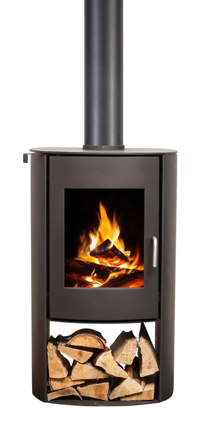
Welcome & Congratulations
Congratulations on the purchase of your Nectre Wood Stove. Please use our convenient online
registration page to record your model and serial numbers for future reference at
www.nectreusa.com
Please carefully read and save these instructions.
Please record your serial number below for future reference, which can be found on the label
on the back of your wood stove.
Serial Number _________________________
Wood is an important renewable energy resource. Please do your part to
preserve our wood supply. Plant at least one tree each year. Future generations
will thank you. P
NO NEED TO RETURN TO THE STORE
Questions with operation or assembly? Require Parts Information?
Product Under Manufacturer’s Warranty?
Contact us at: www.nectreusa.com/contact
For Troubleshooting and Technical Support
OR Toll-Free 1-800-668-6663
Please have your model number and product serial number ready.
2 www.nectreusa.com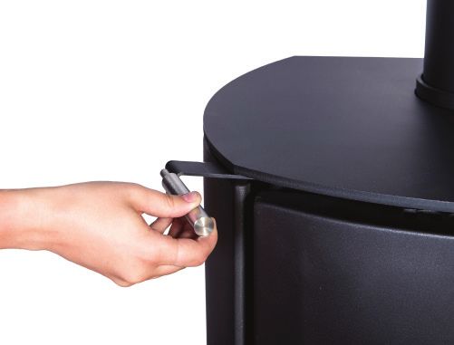
CAUTIONS & WARNINGS
  	CAUTION: Please read this entire manual before you install or use your new stove. Improper
    use or installation could void your warranty. Failure to follow instructions may result in property
    damage, bodily injury, or death.

① For use with solid wood fuel                          ⑩ Normal operation of the stove will result in
   only – preferably dry, seasoned cord wood.               momentary emissions of smoke into the
② Hot while in operation. Keep children, clothing          room when the refueling door is opened and
   and furniture away. Contact may cause skin               closed. It is always recommended to install
   burns.                                                   strategically placed smoke detectors away
                                                            from the stove and to have a fire extinguisher
③ Do not install in a mobile home.                          in a convenient location. Make sure that they
④ Do not burn garbage or flammable chemicals               are not influenced by small and normal wisps
   or fluids such as gasoline, gasoline-type                of smoke that can come out of the stove
   lantern fuel, kerosene, charcoal lighter fluid,          at ignition or refueling but close enough to
   naphtha, engine oil, or similar liquids to start or      provide safety.
   ‘freshen up’ a fire in this stove. Some of these      ⑪ Never over-fire your stove. If any part of
   fuels can generate deadly carbon monoxides.              the stove starts to glow red, over firing is
   Keep all such liquids well away from the stove           happening. To correct over firing adjust the air
   while it is in use.                                      intake control to a lower setting.
⑤ Do not connect to any air distribution or duct        ⑫ Never put wood above the firebrick lining of
   system.                                                  the firebox.
⑥ Do not elevate the fire by use of a log cradle        ⑬ This wood heater needs periodic inspection
   or grates. Build fire directly on a 1 inch layer         and repair for proper operation. It is against
   of ash spread evenly over the base of the                federal regulations to operate this wood
   firebox.                                                 heater in a manner inconsistent with operating
⑦ Do not store fuel within the specified                   instructions in this manual.
   installation clearance areas, or within the space     ⑭ Cracked and broken components, e.g. glass
   required for refueling and ash removal.                  panels or ceramic tiles, may render the
⑧ Always close the door after ignition. Leaving            installation unsafe.
   the door open can cause smoke spillage and            ⑮ This wood heater has a manufacturer-set
   flames to come out of the stove and create               minimum low burn rate that must not be
   dangerous and possibly life-threatening                  altered. It is against federal regulations to alter
   situations.                                              this setting or otherwise operate this wood
⑨ Ensure there are working carbon monoxide                 heater in a manner inconsistent with operating
   and smoke detectors in the home.                         instructions in this manual.

                                                                                                              3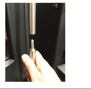
Safety Label
DO NOT REMOVE THIS LABEL/NE PAS ENLEVER CETTE ÉTIQUETTE
CONTACT YOUR LOCAL BUILDING OR FIRE OFFICIALS ABOUT RESTRICTIONS AND INSTALLATION INSPECTION IN YOUR AREA.
CONTACTEZ LE BUREAU DE LA CONSTRUCTION OU LE BUREAU DES INCENDIES AU SUJET DES RESTRICTIONS ET DES INSPECTIONS D’INSTALLATION DANS VOTRE RÉGION
Listed Stove, Solid Fuel Type / Poêle à combustible solide homologué
FOR USE WITH SOLID WOOD FUEL ONLY / POUR USAGE AVEC BOIS SEULEMENT
OMNI Test Laboratories, Inc.
Serial No. / No. de série : Report No. / No. de rapport 0568WS001S
Tested & Portland
Manufactured by Model / Modèle : Nectre N65 Oregon USA Report No. / No. de rapport 0568WS001E
Listed By
Glen Dimplex New Zealand Certified for US and Canada Tested to / Testé selon : UL1482-2011 (R2015)
38 Harris Road
East Tamaki, Aukland 2013 New Zealand ULC S627-00
PREVENT HOUSE FIRES PRÉVENEZ LES INCENDIES
Install and use only in accordance with manufacturer’s Installation Instructions and your local Installer et utiliser conformément au manuel d’installation du fabricant et aux codes du bâtiment
building codes. Contact your local building or fire officials about restrictions and installation locaux. Contacter les autorités de votre localité ayant juridiction concernant les restrictions et
inspection in your area. inspections d’installation.
CAUTION: Refer to local building codes and manufacturer’s instructions for precautions required ATTENTION: Voir les codes locaux et le manuel d’installation du manufacturier pour le passage
for passing a chimney through a combustible wall or ceiling. Do not connect this stove to a de la cheminée à travers un mur ou un plafond combustible.
chimney flue serving another appliance. Do not obstruct the space beneath the stove. Clearances Ne pas raccorder ce poêle à une cheminée déservant un autre appareil. Ne pas obstruer l’espace
may be reduced by methods specified in NFPA211, listed wall shields, or other means approved sous le poêle. Les dégagements peuvent être réduits à l’aide de méthodes spécifiées dans la
by the local building or fire officials. norme NFPA211, de protections murales répertoriées ou de tout autre moyen approuvé par les
agents locaux du bâtiment ou de prévention des incendies.
FREE STANDING INSTALLATION / INSTALLATION AUTOSTABLE
Clearance to combustlbles: Dégagement aux combustibles :
The material for the floor protector of BACK WALL ADJACENT WALL Floor Protector Le matériau utilisé pour le protecteur de
G
this stove must be noncombustible. It
MUR ARRIÈRE MUR ADJACENT Protecteur de plancher plancher de ce poêle doit être incombustible.
H H
45º
must extend beneath the heater and to US CANADA Il doit s’étendre sous l’appareil de chauffage
A
B
F
the front, sides and back as indicated. G N/A 8″ (203 mm) et à l’avant, sur les côtés et à l’arrière, comme
See Installation Manual for details of D E indiqué. Voir le manuel d’installation pour
H 5″ (127 mm) 8″ (203 mm)
ADJACENT WALL
materials that can be used. plus de détails sur les matériaux pouvant être
MUR ADJACENT
C
MUR DE CÔTÉ
I 16″ (406 mm) 18″ (457 mm) utilisés.
SIDEWALL
Refer to table for front, side, and rear
I
FOR REAR HORIZONTAL VENTS
edge dimensions of floor protector from EXTEND PROTECTION UNDER AND Se référer au tableau pour les dimensions
the stove. 2″ EITHER SIDE OF VENT. entre les bords avant, arrière et latéraux du
POUR LES ÉVENTS À L’HORIZONTAL
protecteur de plancher et le poêle.
VERS L’ARRIÈRE, LA PROTECTION
DOIT S’ÉTENDRE EN-DESSOUS ET À
2 PO DE CHAQUE CÔTÉ DE L’ÉVENT.
Dimensions Dimensions
Chimney & Espaces Cheminée
Installation Clearance Connector A B C D E F Installation libres et tuyau A B C D E F
US&Canada Residential Standard Note 1 13 16.5 12 20.5 10.5 18.5 US&Canada Résidentielle Standards Note 1 330 419 305 521 267 470
(in inches) Residential Reduced Note 2 10 13 12 20 6 13.5 (en mm) Résidentielle Réduits Note 2 254 330 305 508 152 343
Note 1: 6 inch diameter, single wall, minimum 24 MSG black or 25 MSG blued steel connector pipe Note 1 : Tuyau d’évacuation en acier noir de minimum 24 MSG ou en acier bleui de 25 MSG
with factory-built chimney listed to either UL 103HT or ULCS629. 6 po de diamètre, à paroi simple, avec cheminée préfabriquée, homologué ULC S629.
Note 2: 6 inch diameter listed double wall chimney connector or Type L vent pipe between stove Note 2 : Tuyau d’évacuation 6 po de diamètre à paroi double ou tuyau d’évacuation de Type L
and chimney. homologué entre le poêle et la cheminée.
Note 3: The minimum clearance from the top of the appliance to the ceiling is 42 inches (1067mm). Note 3 : Le dégagement minimum entre le haut de l’appareil et le plafond est de 42 po (1067 mm).
CAUTION: HOT WHILE IN OPERATION. DO NOT TOUCH. ATTENTION : CHAUD EN FONCTIONNEMENT. NE
PAS TOUCHER. LE CONTACT PEUT CAUSER DES BRÛLURES À LA PEAU.
CONTACT MAY CAUSE SKIN BURNS. KEEP CHILDREN, CLOTHING, FURNISHINGS, AND
COMBUSTIBLE MATERIAL A CONSIDERABLE DISTANCE AWAY. SEE NAMEPLATE AND GARDER LES ENFANTS, LES VÊTEMENTS, LES MEUBLES ET LES MATÉRIAUX
INSTRUCTIONS. DO NOT OVERFIRE. IF HEATER OR CHIMNEY CONNECTOR GLOWS, COMBUSTIBLES ÉLOINGÉS DE L’ESPACE DESIGNÉ DE L’APPAREIL. VOIR
L’ÉTIQUETTE ET LES INSTRUCTIONS. NE PAS SURCHAUFFER. SI LE POÊLE OU
YOU ARE OVERFIRING. INSPECT AND CLEAN CHIMNEY AND CONNECTOR FREQUENTLY.
LE TUYAU DE CHEMINÉE ROUGIT, IL SURCHAUFFE. INSPECTER ET NETTOYER
UNDER CERTAIN CONDITIONS OF USE, CREOSOTE BUILDUP MAY OCCUR RAPIDLY. DO
LA CHEMINÉE ET LE TUYAU CONNECTEUR FREQUEMMENT. SOUS CERTAINES
NOT USE GRATE OR ELEVATE FIRE. BUILD WOOD FIRE DIRECTLY ON HEARTH. DO NOT CONDITIONS, IL SE PEUT QUE LA CREOSOTE S’ACCUMULE RAPIDEMENT. NE
BURN WITH FEED DOOR OPEN. REPLACE FEED DOOR GLASS ONLY WITH 5 MM PAS SURÉLEVER LE FEU. PRÉPARER LE FEU DIRECTEMENT SUR L’ÂTRE. NE
CERAMIC GLASS. PAS BRÛLER LORSQUE LA PORTE DU POÊLE EST OUVERTE. REMPLACER LA VITRE DE LA
THIS WOOD HEATER NEEDS PERIODIC INSPECTION AND REPAIR FOR PROPER OPERATION. PORTE D’ALIMENTATION SEULEMENT AVEC UN VERRE DE CÉRAMIQUE.
CONSULT THE OWNER’S MANUAL FOR FURTHER INFORMATION. IT IS AGAINST U.S. CET APPAREIL DE CHAUFFAGE REQUIERT DES INSPECTIONS ET RÉPARATIONS
FEDERAL REGULATIONS TO OPERATE THIS WOOD HETER IN A MANNER INCONSISTENT PÉRIODIQUES. CONSULTER LE MANUEL DE L‘UTILISATEUR POUR PLUS D’INFORMATION.
WITH THE OPERATING INSTRUCTIONS IN THE OWNER’S MANUAL. OPÉRER CET APPAREIL DE CHAUFFAGE DE FAÇON INCONSISTENTE PAR RAPPORT AU
MANUEL DE L’UTILISATEUR CONSISTE UNE VIOLATION DE LA LOI FÉDÉRALE (É.U.)
U.S. ENVIRONMENTAL PROTECTION AGENCY Date of Manufacture / Date de fabrication
Certified to comply with 2020 particulate emission standards using cordwood. 2019 2020 2021 2022 2023 Jan. Feb. Mar. Apr. May Jun. Jul. Aug. Sep. Oct. Nov. Dec.
AGENCE DE PROTECTION DE L’ENVIRONNEMENT DES É.-U.
Conforme aux normes d’émission de particules de 2020 avec bûches de bois.
Weighted average emission rate/Moyenne pondérée des émissions – 1.98 g/h 7123040100R00
CAUTION
DO NOT OPEN
NO USER-SERVICABLE PARTS INSIDE
SAVE THESE INSTRUCTIONS
4 www.nectreusa.com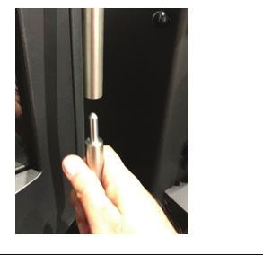
Performance
               Model                                     N65
               Fuel Type                                 Dry Cordwood
               Combustion Technology                     Non-Catalytic
               Recommended heating area ¹                Up to 200 m² (2,152 sq. ft.)
               Maximum burn time ¹                       8-10 hours
               Overall heat output rate ²                14,108 - 68,531 BTU
               (min to max)                              4.13 kW - 20.08 kW
               Average overall efficiency (HHV) ³        69.6%
               (dry cordwood)
               Average overall efficiency (LHV) ⁴        74.5%
               (dry cordwood)
               Weighted Average overall efficiency ²     67.3%
               (dry cordwood)
               Average particulate emission rate ³       1.98 g/hr
               Average CO                                1.258 g/min

 ¹	Recommended heating area and maximum burn time may vary depending on the home’s location,
    stove location, floor plan, degree of insulation, chimney draft, climate, and wood fuel type, quality,
    and moisture level.
 ²	This stove is officially tested and certified by an independent agency for US EPA’s cordwood test
    method as measured per CSA B415.1-10 stack loss method
 ³ Higher Heating Value of the fuel
 ⁴ Lower Heating Value of the fuel

EPA Compliance
This manual describes the installation and operation of the Nectre N65 wood heater. This heater
meets the 2020 U.S. Environmental Protection Agency’s cordwood emission limits for wood heaters
sold after May 15, 2020. Under specific test conditions this heater has been shown to deliver heat at
rates ranging from 14,108 to 68,531 BTU/hr.

                                                                                                        5
Specifications
Maximum log length 320 mm (12 19/32")
Firebox volume 0.047 m³ (1.67 ft³)
Weight 190 kg (419 lbs)
Flue outlet diameter 152 mm (6")
Recommended connector pipe diameter 152 mm (6")
ULC S629, UL103
Type of Chimney HT(21000F)
Alcove installation Not approved
Mobile home installation Not approved
Baffle material Steel
Material Ceramic
Door Glass 431 mm x 325 mm x 5 mm
Size (16 31/32" x 12 ⁷/8" x 13/64")
Material Black Tempered Glass
Pedestal Glass 430 mm x 485 mm x 6 mm
Size (16 59/64" x 19 ³/32" x 15/64")
Braided Ceramic Rope,
Material Round
Door Rope Diameter 13 mm (33/64")
Length 1502 mm (59 ³/8")
Technical Illustrations
Overall Dimensions:
Figure 1
22 ⁷/8" 20"
581 mm 508 mm
11 ³/8"
290 mm
171 mm
6 ³/4"
1037 mm
40 ⁷/8"
22 ³/4" 19 ¹/4"
576 mm 485 mm
6 www.nectreusa.comInstallation
SAFETY NOTICE:
If this stove is not properly installed, a house fire may result. For your safety, follow the installation
instructions. Never use make-shift compromises during the installation of this stove. Contact local
building or fire officials about permits, restrictions, and installation requirements in your area.
The information given on the certification label affixed to the stove always overrides the information
published, in any other media (owner’s manual, catalogs, flyers, magazines and websites.)
Any modification of the appliance that has not been approved in writing by the testing authority
violates ANSI NFPA 211 (USA) and CSA B365 (Canada).
Components
After unpacking your N65 stove, ensure that the parts listed below are included inside the stove
• 2 Refractory Bricks:
- 270 mm x 175 mm x 25 mm
(10 ⁵/8" x 6 ⁷/8" x 1") • 2 Firebrick Retainers (LH & RH)
• Vermiculite Bricks: • Ash Pan
- 2 x 2
63 mm x 165 mm x 25 mm • Door Handle Extension
(10 ¹/2" x 6 ¹/2" x 1")
• 4mm & 5 mm Hex Keys
- 4 x 270 mm x 130 mm x 25 mm
(10 ⁵/8" x 5 ¹/8" x 1")
Assembling the Stove
POSITIONING THE TOP PLATE
Remove the 8 mm (5/16") thick top plate from the box and place on top of the stove locating the hole
in the plate over the flue collar. Adjust the position of the top plate so that there is an even space
between the top plate and the flue collar.
POSITIONING THE ASH PAN
The ash pan slides into the gap created by the 48 mm (1 ⁷/8") spacers between the firebox body and
the base cabinet. The ash pan should slide all the way back, enough so that the door can then be
closed.
DOOR HANDLE EXTENSION
The stainless steel handle of the door will become hot during operation of the stove. The door handle
extension is packed along with the stove, which can be inserted at the bottom of the door handle to
open and close the door during operation. The door handle can be stored in the extension holder
bracket located in the top right corner of the stand.
Positioning the Stove
First review the necessary clearances specified before considering where to position the stove.
Check your local building codes or consult with your local fire department for more information.
The stove must be placed so that no combustibles are within or can swing within 36" (914 mm) of the
front of the stove (doors, drapes, etc)
See the Clearance to Combustible Material section for minimum clearances to combustibles, i.e.
drywall and furniture.
7Installation
Check the practicability of installing the flue system in relation to any obstructing roof beams before
positioning the stove.
Depending on the type of flue used, the clearances to combustible surfaces varies.
WARNING: Do not install this stove in a bedroom.
Outside Air Requirements
The stove requires sufficient fresh air supply to operate. The performance of the stove may be
affected if there is insufficient fresh air for combustion. Modern energy-efficient homes are more
airtight compared to older homes. Airtightness makes a house more susceptible to negative pressure
when combusted air is exhausted through the chimney. Large extraction fans can cause extreme
negative pressure which can lead to air starvation, which negatively impacts the performance of the
stove.
To prevent air starvation, slightly open a nearby window to allow fresh air to enter the room. In
extremely cold regions, opening a window may not be feasible, or icing may block the required
ventilation. Installation of an outside air duct with a rodent screen and rain hood will be required to
overcome the issue of air starvation. Check with local building officials for specific requirements that
apply in certain localities.
Floor Protector (Hearth)
Unless the stove will be standing on a heat resistant floor such as concrete slab with slate or tiles, it
is necessary to provide a floor protector (hearth). The floor protector must be made of a continuous,
noncombustible material such as steel, ceramic tiled floor, cement board, brick, or any other
approved or listed material for floor protection. Materials corresponding to ASTM E136 and UL 763
are considered to be combustible materials, with the exception of gypsum.
Figure 2 shows the minimum size of the floor protector. Refer to the table below for minimum distance
between the edge of the floor protector and the curved front of the edge of the stove and from the
side curved edges and edge of the rear panel. For installations with horizontal rear connector, the
floor protection must extend under and 2" on either side of the connector.
Figure 2
Floor Protector
G
US Canada
H H G N/A 8" (203 mm)
F
H 5" (127 mm) 8" (203 mm)
I 16" (406 mm) 18" (457 mm)
*F
OR REAR HORIZONTAL VENTS
EXTEND PROTECTION UNDER AND
I
2" EITHER SIDE OF VENT
8 www.nectreusa.comInstallation
Clearances to Combustible Material
The minimum clearances shown in the table below have been determined by tests according to
procedures set out in the safety standard ULC-S627-00 for Canada & UL-1482-2011 (R015) for USA.
Figure 3
A
B
45º
E
C F
D
Single Wall Double Wall
Minimum Clearance
Connector Connector
A Back wall to stove rear 13" (330 mm) 10" (254 mm)
B Back Wall to connector pipe 16.5" (419 mm) 13" (330 mm)
C Side wall to stove side 12" (305 mm) 12" (305 mm)
D Side Wall to connector pipe 20.5" (521 mm) 20" (508 mm)
E Corner wall to stove corner 10.5" (267 mm) 6" (153 mm)
F Corner wall to connector pipe 18.5" (470 mm) 13.5" (343 mm)
Back Wall Exit Configuration
Figure 4
Ver.
G
Hor.
D
B
A
H
C
Single Wall Double Wall
Minimum Clearance
Connector Connector
A Back wall to stove rear 17" (432 mm) 10" (254 mm)
B Back Wall to connector pipe 20.5" (521 mm) 13" (330 mm)
C Side wall to stove side 12" (305 mm) 12" (305 mm)
D Side Wall to connector pipe 20.5" (521 mm) 20" (508 mm)
G Ceiling to horizontal connector pipe 18" (457 mm) 16" (407 mm)
H Ceiling to floor 82" (2083 mm) 82" (2083 mm)
9Installation
Chimney Connector
• A chimney connector is required from the flue collar of the stove to a factory-built or masonry
chimney.
• The chimney connector must be clean and in good condition, and be suitable for solid fuel,.
• For use with the N65 stove, the chimney connector MUST be 6″ (150 mm) in diameter, with a
minimum thickness of 24-gauge black steel or 26-gauge blued steel.
• Aluminium and galvanized steel pipe are not acceptable for use with the N65 stove. These
materials cannot withstand the extreme temperatures of a wood stove and emit toxic fumes when
fired.
• No part of the chimney connector may pass through an attic or roof space, closet or other
concealed space, or through a floor ceiling.
WARNING: Do not use the connector pipe as a chimney.
• Each chimney connector or stove pipe section must be installed to the stove flue collar and
to each other with the male (crimped) end toward the stove. Refer to Figure 5. Attach each of
the sections to one another with three equidistant metal screws. This prevents any amount of
condensed or liquid creosote from running down the outside of the pipe or the stovetop. All joints,
including the flue collar connection, must be secured with three sheet metal screws to ensure that
the sections do not separate.
Figure 5
1/4" slope per foot
Install crimped Flow Direction Male Part Downwards
end towards of
stove Flue Gases
3 screws
• For optimal performance, the chimney connector should be as short and direct as possible, with
no more than two 90° elbows. The maximum horizontal run is 36" (915 mm) and a recommended
total length of stovepipe should not exceed 10'. Always slope horizontal runs upward ¼" per foot
toward the chimney.
• All sections of the chimney connectors must be accessible for cleaning. Where passage through a
wall or partition of combustible construction is necessary, the installation must conform to
NFPA 211 or CAN/CSA-B365.
10 www.nectreusa.comInstallation
Chimney Requirements
WARNING: Do not connect this stove to a chimney flue serving another appliance.
WARNING: Do not connect to any air distribution duct or system unless specifically approved for
such installations.
• In Canada: The N65 stove must be connected to a factory-built chimney conforming to
CAN/ULC-S629, standard for 6500C Factory-Built Chimneys.
• UL 103 HT Chimney must be used from the first ceiling or floor or wall penetration to the
chimney cap.
• Use 6" (152 mm) diameter type UL 103 HT chimney from a single manufacturer only. Do not mix
components from different brands. You must purchase and install the ceiling support package
or wall pass-through and “T” section package, firestops (where needed), insulation shield, roof
flashing, chimney cap, etc., from the same manufacturer.
• Follow the chimney manufacturer’s installation instructions, clearances, and requirements.
• The chimney must attain the required height above the roof or other obstructions for safety and
proper draft operation. See Chimney Termination and Height section for details on Chimney
Termination requirements.
• Elbows affect the draft adversely, hence not more than 180º of elbow (two 90º elbows, or two 45º
& one 90º elbows) may be used for the entire system (connector and chimney). Additional elbows
may be used if there is enough draft.
• An effective vapor barrier at the location where the chimney or component penetrates to the
exterior of the structure must be maintained as per the installer’s complying method.
Figure 6
inimum system height 15′ (4.5 m)
Ⓐ M B
Maximum system height 33′ (10 m)
efer manufacturer’s requirements for roof
Ⓑ R
penetration & termination C B
Ⓒ Chimney sections
D
Ⓓ Refer manufacturer’s requirements for ceiling
penetration E
Ⓔ Refer manufacturer’s requirements for
minimum air space to combustible (typically F A
2″ / 51 mm) F
Ⓕ Refer to the Chimney Connector section on
page 11.
11Installation
Chimney Termination & Height
• A chimney termination must have an approved cap (to prevent water from entering.)
• A masonry chimney or a listed factory-built chimney termination must be the required height
above the roof and any other nearby obstructions. The chimney must be at least 3′ (914 mm)
higher than the highest point where it passes through the roof and at least 2′ (600 mm) higher
than the highest part of the roof or structure that is within 10′ (3 m) of the chimney, measured
horizontally.
• Termination must not be located where it will become plugged by snow or other potential
obstructions.
• Refer to Figure 7 for more details on requirements.
Figure 7
Slanted Roofs
Less than 10' (3.1m)
More than 10' (3.1m)
10' (3.1m)
2' (0.61m)
Minimum Chimney must
extend 3' (0.92m)
2' (0.61m) above the roof
Chimney must Minimum
extend 3' (0.92m)
above the roof
Height above any
roof surface within
10' (3.1m) horizontally
Flat Roofs
Less than 10' (3.1m)
Chimney must More than 10' (3.1m)
extend 3' (0.92m)
above the roof No height above
parapet shall be
required when
distance from walls
or parapet is more
than 10' (3.1m)
2' (0.61m)
Minimum
12 www.nectreusa.comInstallation
Figure 8
Standard Ceiling with a Factory-Built Chimney
Refer to Chimney Termination
& Height section for details Refer to chimney manufacturer's
on chimney cap. instructions and clearance
requirements for roof penetrations.
A storm collar and flashing or
Chimney sections
radiation shield may be required in
some cases.
Chimney insulation
Refer to chimney manufacturer's Refer to chimney manufacturer's
instructions and clearance instructions for minimum air
requirements for floor penetrations. space to combustibles
A ceiling support is required. An
attic insulation shield is required
Termination Height
where insulation is present.
Minimum 15' (4.57 m)
Chimney connector sections Maximum 33' (10 m)
Refer to Clearances to
Refer to Floor Protector section Combustible Materials section
for the required dimensions of the for these stove clearances.
floor protector.
Figure 9
Cathedral Ceiling with a Factory-Built Chimney
Refer to Chimney Termination
& Height section for details
on chimney cap.
Chimney sections Refer to chimney manufacturer's
instructions and clearance
requirements for roof penetrations.
A storm collar, flashing, and
cathedral-style chimney support
Refer to chimney manufacturer's required. A radiation shield may also
instructions for minimum air space be required in some cases.
to combustibles.
Termination Height
Minimum 15' (4.57 m)
Chimney connector sections Maximum 33' (10 m)
Refer to Floor Protector section Refer to Clearances to
for the required dimensions of the Combustible Materials section
floor protector. for these stove clearances.
13Installation
Exterior Factory-Built Chimney
A vertical rise of 74" of chimney connector is required, measured from the floor, before entering a
Class ‘A’ wall penetration. If the chimney is to pass through the lower wall, a NFPA 211 wall
pass-through may be used, provided it meets the local building codes and is approved by the local
building authority.
WALL PENETRATION UNDER 74"
In cases where the chimney connector must be passed through a combustible wall or partition under
74", the following NFPA 211 method may be used if local building code permits. Check with local
authorities before installation to ensure all necessary requirements have been met. See Figure 10
for details on a wall pass-through based on the NFPA 211 standards. After pass-through, a Class A
chimney may be used in accordance with the chimney installation instructions.
Figure 10 Refer NFPA 211 for
full details on
Wall Pass-Through
Minimum
12" (305mm)
Brick
Fire Clay Thimble
Combustible Materials
WALL PENETRATION 74" OR GREATER
A vertical rise of 74" of chimney connector is required, measured from the floor to the centerline of the
flue when it makes a 90º turn, before entering a Class ‘A’ wall penetration.
Figure 11
UL 103 HT
Chimney System
Refer Clearances to
Combustible Materials
section for all Stove
Clearances
Refer to the Chimney
Minimum 74” (1.88 m)
manufacturer's instructions
and clearances for wall
Chimney penetrations. A wall radiation
Connector shield (thimble) is required
Sections
14 www.nectreusa.comInstallation
Interior Or Exterior Masonry Chimney
CAUTION: Not permitted in Canada unless full reline is used
For this type of installation use, a UBC approved masonry connector or other method approved by
the NFPA 211 Standard. Refer to the Chimney Connector section of this manual for requirements.
A full reline (positive connection) is highly recommended when venting through a masonry chimney.
It is recommended that a minimum 3' chimney be added to the minimum system height for every 1’ of
horizontal run.
Figure 12
! NOTE: The chimney must have a clay tile
liner. If it does not, the installation must
use a positive connection (full reline). The
entire fireplace and chimney must be clean,
undamaged, and meet all local building
codes (UBC, etc.) Damage must be repaired
prior to installation. The chimney must be 15'
(4.57 m) to 33' (10 m) tall. Clay liner
This type of
installation requires
Refer to the Stove a UBC approved
Placement Requirements masonary connector
section for minimum or a factory-built
clearances required. (U.L. Listed) wall
thimble.
Chimney
Connector
Sections
Refer to the Floor
Protector section for the
required dimensions of
the floor protector Ensure the
clean-out seals
in place
15Operating Instructions
Air Controls
The Nectre N65 has a single top air control for controlling the fire.
This control allows air to enter the firebox from above the door where it is then drawn down into the
base of the fire while keeping the glass clean.
Open the top air control before opening the door to eliminate the chance of back draft and/or smoke
entering the room.
Figure 13
Top air
control
handle
Door Handle
WARNING: Door handle may get hot if appliance has been left in high burn setting for an
extended period of time.
The N65 is supplied with a stainless steel handle extension which can be inserted into the end of the
door handle. This extension allows the door to be opened and closed without the risk of burn to the
user's hand. This handle can also be used for operating the air control handle, as shown in Figure 13.
The door handle extension should be stored in the compartment at the right hand top corner of the
wood fuel storage compartment.
Figure 14
First Time Use
During the first few burns that the appliance is used, it may give off odorous non-toxic fumes. This is
due to the paint curing.
Do not touch the paint while it is curing because it can leave a permanent mark on the appliance.
Once the paint has cured it will not re-occur.
Keep the room well ventilated until these fumes have cleared.
16 www.nectreusa.comOperating Instructions
Fuel Selection
Firewood with a moisture content of less than 25% (dry basis) must be used. For best results, wood
should not exceed 270-300 mm (10 ⁵/8" - 11 ⁷/8") in length and 150 mm (5 ⁷/8") diameter. The use of
oversized wood will result in the stove not operating at its optimum efficiency.
It is better to burn several smaller pieces of wood than one large single piece.
Newly cut wood should be allowed to dry/season for 12 months before use. Wood should be stored in
an environment protected from the weather to minimize any potential moisture content.
The use of poor-quality timber:
• Causes low combustion efficiency
• Produces poor emissions and excess smoke.
• Results in additional build-up of creosote (soot) in the flue which will then require regular cleaning
and could eventually result in a flue fire if not properly maintained.
AUTION: Do not burn:
C
• Unseasoned, painted, or treated wood.
• Garbage
• Lawn clippings or yard waste
• Materials containing rubber, including tires
• Materials containing plastics and solvents
• Materials containing asbestos
• Construction or demolitions debris
• Railroad ties or pressure-treated wood
• Manure or animal remains
• Salt water driftwood or other previously salt water saturated materials
• Paper products, colored paper, cardboard, Plywood or particle board
The prohibition against burning these materials does not prohibit the use of fire starters made from
paper, cardboard, saw dust, wad, and similar substances for the purpose of starting a fire in an
affected wood stove.
17Operating Instructions
Starting the Fire
We recommend using a top-down fire starting method,
as this improves combustion, creating a cleaner burning Figure 15
fire.
1. Place 2-4 large logs (maximum 11 ⁷/8" x 5 ⁷/8") at the
bottom of the firebox next to each other. For optimal
burn conditions, place the logs in a front to back
orientation (right angles to the door opening).
2. Place medium-sized logs on top, perpendicular to the
ones at the bottom, creating a criss-cross formation.
3. Place a few layers of smaller pieces of kindling on top
in a criss-cross formation
4. Place firelighters and/or paper between the pieces of kindling.
5. Open the air control by pulling it all the way out.
6. Light the paper or firelighters.
7. Once the fire is established, adjust the air control to the desired position for the required
heat output.
Maintaining the Fire
• After establishing the fire and loading it with larger pieces of wood, leave it running with the air
control fully open. This setting is not the most energy efficient as some heat is lost up the flue
instead of being transferred into the room. It is recommended to close the air control partially to
achieve better efficiency and longer burn time. See 'Controlling the Heat Output' for more details.
• Running the appliance with the door open will not produce maximum heating in the room as it will
draw a lot of already warmed air out of the room.
! NOTE: Do not overload firebox with fuel.
Controlling the Heat Output
• The heat output of the stove can be reduced by closing the air control (slide handle to the right.)
This will restrict the oxygen supplied to the fire, thereby slowing down the rate at which the wood
burns.
• This setting provides the best energy efficiency as the wood burns for longer. However, if not
operated correctly may result in higher particulate emissions.
• Prior to closing the air control, ensure that the fire is burning briskly. This may require leaving the
air control fully open for 10-15 minutes before shutting down.
• For the optimum balance between clean burning and efficiency, open the air control 3-5 mm
(1/8-1/4").
• The air control can be adjusted to any position to provide heat output versus burn time.
18 www.nectreusa.comOperating Instructions
Refueling
It is recommended to burn wood in cycles. Once the firewood is fully combusted, an additional load of
wood can be placed on the hot coals to be reignited.
1. Open air control before opening door.
2. Rake / break up any existing coals.
3. Load the wood with the length orientated front to back.
4. Best results will be achieved by loading several smaller pieces of wood rather than one large
piece.
5. Close door with air control fully open, and leave for minimum of 10 minutes to allow the fresh
wood to catch.
6. After 10-15 minutes, the air control can be adjusted to the desired heat output setting.
Burning Tips
FUEL QUALITY
1. Use wood with a moisture content of less than 25% (dry basis). Logs should not feel moist or
damp, or have moss and fungal growths.
2. Symptoms related to wet wood:
• Difficulty starting and keeping a fire burning well
• Smoke and small flames
• Dirty glass and/or fire bricks
• Rapid creosote build-up in the flue/chimney
• Low heat output
• Short burn times, and blue/grey smoke from the flue/chimney outlet
3. Run the appliance at high heat output for a short period each day to avoid large build-up of tars
and creosote within the appliance and flue.
FLUE DRAFT
The flue has two main functions:
1. To remove smoke, gases and fumes from the appliance.
2. To provide a sufficient amount of draft (suction) in the appliance to ensure the fire keeps burning.
Draft is caused by the rising hot air in the flue when the fire has been lit.
The position, height and size of the flue can affect the performance of the flue draft. Refer to
installation guide for details on flue installation.
Factors affecting the flue draft include:
• Insufficient flue height
• Trees or other buildings nearby causing turbulence
• High and gusty winds
• Outside temperature and weather conditions
• Blocked flue
For advice on the correction of persistent flue problems consult your dealer/installer or local building
code inspector for more information.
19Operating Instructions
Flue / Chimney Fire
If a flue/chimney fire occurs:
• Shut air slide control fully to smother the fire.
• C ontact your local, municipal or state/provincial fire authority for information on how to handle a
chimney fire. Have a clearly understood plan to handle a chimney fire.
• D o not use the appliance after a flue fire until an accredited installer or fire official assesses the
cause and any resultant damage.
Troubleshooting Tips
1. Glass in door blackening — this can have several possible causes:
• Burning unseasoned wood — if the wood is too wet, it will cause the glass to blacken.
• Appliance operated at low temperature — after an overnight burn where the air slide control has
been fully closed, the glass may have blackened. When the fire is re-stoked and burning on the
high heat setting, the blackened glass should self-clean.
• P roblems with the flue — insufficient flue draft can cause the glass to blacken. If the flue is
too short, not properly insulated, or in a position that results in a downdraft, then there will be
insufficient flue draft. Contact the installer should this happen.
2. Trouble starting the fire — if all ash has been removed from the firebox, then it can upset the
supply of air to the base of the fire. Retain some ash when cleaning out the firebox to help restart
the fire.
3. Smoke enters room while re-loading - Always open the door in stages
- Switch the air control to the fully open position and wait at least 30 seconds before continuing.
- Unlatch the door using the door handle extension or gloves, and keep it slightly ajar for
15-20 seconds.
- Open the door fully.
4. Stove does not burn hot enough
- Wet or poor quality firewood is the main cause of poor performance of the stove. Refer to Fuel
Selection section for information on the appropriate fuel to burn.
- Insufficient draft - Chimney height and outside conditions can affect the flue draft. Adding extra
length of chimney or a draft-inducing cap can help solve the issue. Consult your dealer or installer
for advice.
5. Glass cracking — Do not over tighten the screws on the stainless steel strips that hold the door
glass in place. Otherwise, expansion of the door may cause the glass to crack.
ARNING: Never operate a stove with cracked glass. The glass must be replaced before using
W
the appliance again.
20 www.nectreusa.comMaintenance
Inspection & Cleaning
1. It is important to establish a routine for the fuel, wood stove and firing technique. Check daily for
creosote buildup. Be aware that the hotter the fire the less creosote is deposited, and weekly
cleaning may be necessary for mild weather even though monthly cleaning may be enough in the
coldest months.
2. Ensure that the door seals are in good condition. If they are worn, replace the door seals.
3. Inspect and clean the glass regularly in order to detect any cracks. If a crack is present, allow the
fire to go out and the stove to cool before repairing.
4. A sufficiently hot fire will burn away any deposits left from a long slow burn. The glass can be
cleaned with dampeneded newspaper with ash or a non-caustic oven cleaner. It is not advisable
to use a cleaner that contains caustic or abrasive ingredients. Do not clean with alcohol based
cleaners. The glass should be washed only when the stove is cold to facilitate good operational
practices.
5. Do not abuse the glass door by striking or slamming shut. Do not use the stove if the glass is
broken. If the glass breaks, replace only with the same 5 mm (0.2") ceramic glass supplied from
your dealer. Never substitute other materials for the glass.
6. The outside panels of the appliance can be cleaned with a dry cloth or soft rag. Do not dampen.
Household detergents and abrasive cleaners may damage the paint on the panels or emit bad
odors while running the fire.
7. Over the years, the black paint will fade and can be touched up with high heat resistant metallic
black paint. Stove Bright Metallic Black 6309 VHT paint is recommended.
8. Depending on quality of maintenance, there may be signs of rust (corrosion) on the body of the
unit. To correct this, sand the affected area and paint using high heat resistant metallic black paint.
Ash Removal
Depending on the type of wood burnt and frequency, the ashes will need removing every
2 to 6 weeks.
Excess ashes should be removed when necessary. Make sure the stove is completely cold before
you remove the ashes. Remove the log retainer grill in order to remove the ash with ease.
Scoop out the ashes and place them in a non-combustible or a metal container with a tight-fitting lid.
The closed container of ashes should be placed on a noncombustible floor or on the ground, well
away from all combustible material, pending final disposal. If the ashes are disposed of by burial in
soil or otherwise locally dispersed, they should be retained in the closed container until all embers
have thoroughly cooled.
21Maintenance
Creosote – Formation & Need for Removal
1. When wood is burned slowly, it produces tar and other organic vapors, which combine with
expelled moisture to form creosote. The creosote vapors condense in the relatively cool chimney
flue of a slow-burning fire. As a result, creosote residue accumulates on the flue lining. When
ignited this makes an extremely hot fire.
2. To prevent creosote buildup:
• Always burn dry wood. This allows clean burns and higher chimney temperatures, therefore
less creosote deposit.
• Leave the air control fully open for about 10-15 minutes every time you reload the stove to
bring it back to proper operating temperatures. The secondary combustion can only take place
if the firebox is hot enough.
3. The chimney connector and chimney should be inspected at minimum every two months to determine
if creosote buildup has occurred. If creosote has accumulated, it should be removed to reduce the risk
of a chimney fire. Have your chimney cleaned at least once a year.
AUTION: Operating N65 stove continually at a low burn rate (air starvation) or using green
C
(unseasoned) wood will increase the formation of creosote.
ARNING: If you are not certain of creosote inspection, contact your dealer or local chimney
W
sweep for a full inspection. Excess creosote buildup may cause a chimney fire that may result in
property damage, injury, or death,
22 www.nectreusa.comService
Always use a qualified technician or service agency to repair this unit.
Replacing the Firebricks
Over time the firebricks may become cracked and crumble away. If this happens they should be
replaced soon after.
To replace the firebricks:
1. Remove all ash.
2. Raise the brick retainer so that the bricks can be removed.
3. Replace with new bricks, refractory bricks in the Figure 16
rear, and vermiculite bricks in the sides and base. Refit LH Brick
brick retainer. Retainer Refractory Brick
Replacing the Brick Retainer RH Brick
Retainer
Over time the original brick retainer may burn out, in which
case it can be replaced with a new one.
To replace the brick retainer:
1. Raise the old brick retainer and remove the firebricks.
Remove the old retainer.
2. Refit the firebricks and then fit the retainer over the top
locking them into position.
Vermiculite Brick
Replacing the Door Glass
This task may be easier with the door removed from the
appliance and laid horizontally on a work-bench. When
replacing the glass, the glass gasket should also be replaced to make sure it is properly sealed.
To remove the door:
1. With the Allen key supplied, remove the top air control handle from the air slide.
2. Open the door 90°.
3. With one hand on top of the door and the other supporting it underneath, raise it on the hinge pin
until the top door hinge clears the top of the hinge pin.
4. Lower the door until the lower door hinge clears the bottom of the pin.
To replace the door glass:
1. The door glass is held in position by the rectangular glass retainer fixed by four M6 screws, two at
the top and two at the bottom.
2. Using the 4 mm Allen key supplied with the stove, remove the four screws and the glass retainer.
3. Remove the glass and the old door seal rope.
4. The new glass will have been supplied with a length of grey door seal with adhesive strip on one
side. Remove the wax paper backing from the adhesive and stick the door seal along the 5 mm
thick edge of the glass. With the forefinger and thumb fold the door seal over each side of the
glass. Do this around the external edge of the glass plate.
5. Refit the new glass with door seal into position in the door. Place the glass retainer over the top
and fasten with the four M6 screws.
! NOTE: Take extra care not to over-tighten the screws, otherwise the glass will crack when the
stove gets hot and the door expands.
23Service
Replacing the Door Seal
This task may be easier with the door removed from the stove and laid horizontally on a workbench
(refer to page 16 on how to remove the door).
1. Remove any old seal from the door.
2. Clean out the groove in the door in which the seal was bedded using a flat-end screw driver
or equivalent.
3. Run a thin line of clear roof and gutter silicone along the groove.
4. Starting with the end that has the silver tape around it, press the new door seal rope into the
groove on the door.
5. Towards the end, there will be a small amount of excess rope. Trim this to the correct length,
remove the backing from the adhesive silver tape supplied with the rope, and wrap the tape
around the end that has been trimmed. Fit the end of the rope into the groove.
6. Refit the door if it has been removed and close.
Adjusting the Door Latch
If the door does not close firmly, the door latch will need to be adjusted.
1. Using the 4 mm Allen key supplied with the stove, slightly loosen the two screws fastening the
latch to the side of the firebox body.
2. Gently tap the latch down only a millimeter to start with.
3. Retighten the screws and test for any improvement.
4. If no improvement, repeat process until door can be closed firmly.
Replacing the Main Baffle
! NOTE: The main baffle assembly is heavy. Care should be taken when handling the baffle both
inside and outside the firebox to avoid injury. This service should be performed by a trained service
technician.
Use the following procedure to remove the existing main baffle from the firebox :
1. Remove the stove door. Refer to instructions under the Replacing Door Glass procedure.
2. Remove both the left (LH) and right (RH) brick retainers.
3. Remove all four side vermiculite Figure 17
boards & two rear refractory bricks.
4. On the rear of the stove - Using
small wrench, remove the 4 dome
nuts (Figure 17).
5. Remove the top half shield A and
the rearmost shield B along with
the spacers.
24 www.nectreusa.comService
6. Using the 4 mm hex key supplied with the stove, remove the 3 M8x16 Hex screws that hold the
main baffle and the firebox together. Ensure that the baffle is supported and pushed back in
place so that it does not slip from the support ledge.
7. Remove the main baffle. Note that there is a very small clearance between the width of the baffle
assembly and the firebox. For that reason, avoid twisting the baffle along its vertical axis and
jamming it while unhooking and taking it out of the firebox. To remove the main baffle, refer
to Figure 18:
① Lift the baffle upward and then tilt it so that it comes down from the support ledge.
② Once off the ledge, keep rotating
③ Simultaneously drop it down further
④ Take it out of the firebox.
8. Follow above the procedure outlined in step 7 in reverse order to install the replacement baffle.
! NOTE: Ensure that the replacement baffle has an insulation blanket glued to the top.
Figure 18
25Service
Replacing the Top Baffle
The top baffle plate can be accessed only after removing the main baffle. The top baffle plate is held
in place by two side “T” support tabs and one long rear support tab (Figure 19). The top baffle should
always be positioned all the way to the rear of the firebox. While manufacturing, this baffle is glued
to the rear of the firebox so that it remains in place during transportation or installation of the stove.
Remove the main baffle assemble before Figure 19
proceeding.
1. Tap the bottom of the top baffle until it
comes loose.
2. Remove the top baffle from the firebox
(Figure 20):
① Slide the baffle towards the front of the
firebox until it slips from its rear support
tab.
② Once it slips, the baffle plate will swing
and drop down from its side supports.
! NOTE: Compared to the main baffle, the top
baffle plate is smaller and more lightweight in
relation to the width of the firebox, so it will come
out more easily.
3. Use the above steps a and b in reverse order to
install the replacement top baffle. Make sure the
baffle plate is inserted into side “T” tabs from the
rear first.
Figure 20
26 www.nectreusa.comReplacement Parts List
Part Description Part number
Door
Door Glass (with Tape) 770384
Door Rope 770414
Complete Door Assembly with Glass 770302
Door Handle Extension 770399
Door Handle Latch Kit 770430
Firebricks
Base Vermiculite Board (x 2) 770381
Rear Refractory Firebrick (x 2) 770382
Side Vermiculite Board (x 4) 770383
Brick Retainer 770312
Firebox
Upper Baffle 770317
Main Baffle with Ceramic Blanket 770313
Log Retainer Grill 781166
Ash Tray 770307
Air Slide Assembly 770369
Stand Glass 770398
27Warranty
Glen Dimplex Americas Ltd. (Glen Dimplex Americas herein) warrants this wood stove to be able
to operate under normal use and service and within 10 years from date of the original purchase on
the terms herein shall repair or replace without cost to the original customer any part thereof which
shall be returned to our factory which our inspection shows would prevent operation (transportation
charges prepaid). This warranty does not apply to firebricks, brick retainer, baffle, door seal, glass nor
discoloration of the surface or tarnishing of gold fittings all of which require normal service to maintain
them. The warranty is void if the unit is used to burn materials for which the unit is not certified by the
EPA and void if not operated according to the owner’s manual.
Under the terms of this warranty, Glen Dimplex Americas assumes no responsibility for the labor
costs involved in removing or replacing the stove. Nor shall Glen Dimplex Americas be liable for
any injury, loss, or damage (direct, indirect, or consequential) arising out of the use or inability to
use the product, or its removal and replacement. All other stove warranties, expressed or implied
are excluded to the extent possible at law. Consumers also have rights under relevant State and
Commonwealth Laws.
The Retailer does not have the authority to alter this warranty. For further information please contact
Glen Dimplex Americas.
Defects must be brought to the attention of Glen Dimplex Americas by contacting Technical Support
at www.nectrausa.com/contact or by calling 1-800-668-6663. Please have proof of purchase, model
number, and serial number available when calling. Limited warranty requires a proof of purchase of
the product.
Technical Support
Technical and troubleshooting support, as well as a list of replacement parts can be found on
www.nectreusa.com/resources-downloads
28 www.nectreusa.comN65 Wood Stove Manufactured by: Glen Dimplex New Zealand 38 Harris Road, East Tamaki P.O.Box 58473, Botany, Manukau – 2163 Phone: 0800 666 2824 Fax: 0064 9 274 8472 www.glendimplex.co.nz In keeping with our policy of continuous product improvement, we reserve the right to make changes without notice. ©2020 Glen Dimplex Americas | www.nectreusa.com
You can also read