Hardware Assisted Virtualization Intel Virtualization Technology - Mat ıas Zabalj auregui
←
→
Page content transcription
If your browser does not render page correctly, please read the page content below
Hardware Assisted Virtualization
 Intel Virtualization Technology

        Matı́as Zabaljáuregui
           matiasz@info.unlp.edu.ar

       Buenos Aires, Junio de 2008

                      1
Index
1 Background, motivation and introduction to Intel Virtualiza-
tion Extensions 3
1.1 Challenges to virtualizing Intel architecture . . . . . . . . . . . . 3
1.1.1 Ring aliasing . . . . . . . . . . . . . . . . . . . . . . . . . 3
1.1.2 Address-space compression . . . . . . . . . . . . . . . . . 3
1.1.3 Nonfaulting access to privileged state . . . . . . . . . . . 4
1.1.4 Adverse impacts on guest transitions . . . . . . . . . . . . 5
1.1.5 Interrupt virtualization . . . . . . . . . . . . . . . . . . . 5
1.1.6 Ring compression . . . . . . . . . . . . . . . . . . . . . . . 5
1.1.7 Access to hidden state . . . . . . . . . . . . . . . . . . . . 6
1.2 Addressing virtualization challenges in software . . . . . . . . . . 6
1.3 Intel Virtualization Technology . . . . . . . . . . . . . . . . . . . 6
1.3.1 Virtual Machine Architecture . . . . . . . . . . . . . . . . 6
1.3.2 Introduction to VMX operation . . . . . . . . . . . . . . . 7
1.3.3 Life Cycle of VMM software . . . . . . . . . . . . . . . . . 7
1.3.4 Virtual Machine Control Structure . . . . . . . . . . . . . 8
1.3.5 Restrictions on VMX operation . . . . . . . . . . . . . . . 8
2 Virtual Machine Control Structure 9
2.1 Overview . . . . . . . . . . . . . . . . . . . . . . . . . . . . . . . 9
2.2 Format of the VMCS region . . . . . . . . . . . . . . . . . . . . . 10
2.3 Organization of VMCS data . . . . . . . . . . . . . . . . . . . . . 10
2.4 Guest-State Area . . . . . . . . . . . . . . . . . . . . . . . . . . . 10
2.4.1 Guest Register State . . . . . . . . . . . . . . . . . . . . . 11
2.4.2 Guest Non-Register State . . . . . . . . . . . . . . . . . . 12
2.5 Host-State Area . . . . . . . . . . . . . . . . . . . . . . . . . . . . 12
2.6 VM-Execution Control Fields . . . . . . . . . . . . . . . . . . . . 13
2.6.1 Pin-Based VM-Execution Controls . . . . . . . . . . . . . 13
2.6.2 Processor-Based VM-Execution Controls . . . . . . . . . . 13
2.6.3 Exception Bitmap . . . . . . . . . . . . . . . . . . . . . . 13
2.6.4 I/O-Bitmap Addresses . . . . . . . . . . . . . . . . . . . . 15
2.6.5 Time-Stamp Counter Offset . . . . . . . . . . . . . . . . . 15
2.6.6 Guest/Host Masks and Read Shadows for CR0 and CR4 . 15
2.6.7 CR3-Target Controls . . . . . . . . . . . . . . . . . . . . . 15
2.6.8 Controls for CR8 Accesses . . . . . . . . . . . . . . . . . . 16
2.6.9 MSR-Bitmap Address . . . . . . . . . . . . . . . . . . . . 16
2.6.10 Executive-VMCS Pointer . . . . . . . . . . . . . . . . . . 17
2.7 VM-Exit Control Fields . . . . . . . . . . . . . . . . . . . . . . . 17
2.7.1 VM-Exit Controls . . . . . . . . . . . . . . . . . . . . . . 17
2.7.2 VM-Exit Controls for MSRs . . . . . . . . . . . . . . . . . 17
2.8 VM-Entry Control Fields . . . . . . . . . . . . . . . . . . . . . . 18
2.8.1 VM-Entry Controls . . . . . . . . . . . . . . . . . . . . . . 18
2.8.2 VM-Entry Controls for MSRs . . . . . . . . . . . . . . . . 18
2.8.3 VM-Entry Controls for Event Injection . . . . . . . . . . 18
2.9 VM-Exit Information Fields . . . . . . . . . . . . . . . . . . . . . 19
2.9.1 Basic VM-Exit Information . . . . . . . . . . . . . . . . . 19
2.9.2 Information for VM Exits Due to Vectored Events . . . . 19
2.9.3 Information for VM Exits Due to Instruction Execution . 20
13 VMX non-root operation 20
3.1 Instructions that cause VM exits . . . . . . . . . . . . . . . . . . 20
3.1.1 Instructions That Cause VM Exits Unconditionally . . . . 20
3.1.2 Instructions That Cause VM Exits Conditionally . . . . . 21
3.2 Other causes of VM exits . . . . . . . . . . . . . . . . . . . . . . 23
3.3 Changes to instruction behavior in VMX non-root operation . . . 25
3.4 Other Changes in VMX non-root operation . . . . . . . . . . . . 28
3.4.1 Event Blocking . . . . . . . . . . . . . . . . . . . . . . . . 28
3.4.2 Treatment of Task Switches . . . . . . . . . . . . . . . . . 28
4 Memory Virtualization 29
4.1 Processor Operating Modes & Memory Virtualization . . . . . . 29
4.2 Guest & Host Physical Address Spaces . . . . . . . . . . . . . . . 29
4.3 Virtualizing Virtual Memory by Brute Force . . . . . . . . . . . . 30
4.4 Alternate Approach to Memory Virtualization . . . . . . . . . . . 31
5 Handling interruptions in VMM 32
5.1 VMX support for handling interrupts . . . . . . . . . . . . . . . . 32
5.2 External interrupt virtualization . . . . . . . . . . . . . . . . . . 35
5.2.1 Virtualization of Interrupt Vector Space . . . . . . . . . . 35
5.2.2 Control of Platform Interrupts . . . . . . . . . . . . . . . 37
5.2.3 Examples of Handling of External Interrupts . . . . . . . 39
A APPENDIX: First steps in programming a VMM 42
A.1 Discovering support for VMX . . . . . . . . . . . . . . . . . . . . 42
A.2 Enabling and entering VMX operation . . . . . . . . . . . . . . . 42
A.3 Software Access to the VMCS and related structures . . . . . . . 42
A.3.1 Software Access to the Virtual-Machine Control Structure 42
A.3.2 VMREAD, VMWRITE, and Encodings of VMCS Fields . 43
A.3.3 Software Access to Related Structures . . . . . . . . . . . 43
A.3.4 VMXON Region . . . . . . . . . . . . . . . . . . . . . . . 43
A.3.5 Using VMCLEAR to initialize a VMCS region . . . . . . 44
A.3.6 VMCS states . . . . . . . . . . . . . . . . . . . . . . . . . 44
A.4 Supporting processor operating modes in guest invironments . . 45
A.4.1 Emulating Guest Execution . . . . . . . . . . . . . . . . . 46
A.5 Using VMX instructions . . . . . . . . . . . . . . . . . . . . . . . 46
A.6 VMM setup & tear down . . . . . . . . . . . . . . . . . . . . . . 46
A.7 Preparation and launching a virtual machine . . . . . . . . . . . 47
A.8 Handling of VM exits . . . . . . . . . . . . . . . . . . . . . . . . 48
A.8.1 Handling VM Exits Due to Exceptions . . . . . . . . . . . 49
A.9 Multiprocessor considerations . . . . . . . . . . . . . . . . . . . . 50
A.9.1 Initialization . . . . . . . . . . . . . . . . . . . . . . . . . 50
A.9.2 Moving a VMCS Between Processors . . . . . . . . . . . . 51
A.10 Performance considerations . . . . . . . . . . . . . . . . . . . . . 52
21 Background, motivation and introduction to
Intel Virtualization Extensions
1.1 Challenges to virtualizing Intel architecture
Established and emerging applications motivate strong support for virtualiza-
tion in both server and client computing systems. Unfortunately, the IA-32
and Itanium architectures impose many challenges to providing such support.
Software techniques exist that address some of those challenges.
Intel microprocessors provide protection based on the concept of a 2-bit
privilege level, using 0 for most-privileged software and 3 for the least privileged.
The privilege level determines whether privileged instructions, which control
basic CPU functionality, can execute without fault; it also controls address-
space accessibility based on the configuration of the processor’s page tables
and, for IA-32, segment registers. Most IA software uses only privilege levels
0 and 3, as Figure 1a illustrates. For an OS to control the CPU, some of its
components must run with privilege level 0. Because a VMM cannot allow a
guest OS such control, a guest OS cannot execute at privilege level 0. Thus,
IA-based VMMs must use ring deprivileging, a technique that runs all guest
software at a privilege level greater than 0. A VM could deprivilege a guest OS
by running it either at privilege level 1 (the 0/1/3 model) or at privilege level 3
(the 0/3/3 model).
Figures 1b and 1c illustrate these choices. Although the 0/1/3 model sup-
ports simpler VMMs, it cannot be used on IA-32 processors for guests in 64-bit
mode. The 64-bit mode is part of Intel’s EM64T (Extended Memory 64 Tech-
nology), the 64-bit extension to IA-32. Ring deprivileging causes numerous
virtualization challenges. Intel virtual technology extensions (vt-x) solve vir-
tualization challenges in part by allowing guest software to run at its intended
privilege level. Guest software is constrained, not by privilege level, but be-
cause —for VT-x— it runs in VMX non-root operation. Figure 1d illustrates
this usage.
1.1.1 Ring aliasing
Ring aliasing refers to problems that arise when software is run at a privilege
level other than the level for which it was written. An example in IA-32 is the
PUSH instruction (which pushes its operand on the stack) when executed with
the CS register (part of which is the current privilege level). A guest OS could
easily determine that it is not running at privilege level 0.
1.1.2 Address-space compression
Operating systems expect to have access to the processor’s full virtual address
space, known as the linear-address space in IA-32. A VMM must reserve for
itself some portion of the guest’s virtual-address space. The VMM could run
entirely within the guest’s virtual-address space, which allows it easy access to
guest data, although the VMM’s instructions and data structures might use a
substantial amount of the guest’s virtual-address space. Alternatively, the VMM
could run in a separate address space, but even in that case the VMM must use
a minimal amount of the guest’s virtual-address space for the control structures
3Figure 1: rings rings rings
that manage transitions between guest software and the VMM. (For IA-32, these
structures include the IDT and the GDT, which reside in the linear-address
space.) The VMM must prevent guest access to those portions of the guest’s
virtual-address space that the VMM is using. Otherwise, the VMM’s integrity
could be compromised if the guest can write to those portions, or the guest
could detect that it is running in a virtual machine if it can read them. Guest
attempts to access these portions of the address space must generate transitions
to the VMM, which can emulate or otherwise support them. The term address-
space compression refers to the challenges of protecting these portions of the
virtual-address space and supporting guest accesses to them.
1.1.3 Nonfaulting access to privileged state
Privilege-based protection prevents unprivileged software from accessing certain
components of CPU state. In most cases, attempted accesses result in faults,
allowing a VMM to emulate the desired guest instruction. However, the IA-
32 architecture includes instructions that access privileged state and do not
fault when executed with insufficient privilege. For example, the IA-32 regis-
ters GDTR, IDTR, LDTR, and TR contain pointers to data structures that
control CPU operation. Software can execute the instructions that write to, or
load, these registers (LGDT, LIDT, LLDT, and LTR) only at privilege level 0.
However, software can execute the instructions that read, or store, from these
registers (SGDT, SIDT, SLDT, and STR) at any privilege level. If the VMM
maintains these registers with unexpected values, a guest OS using the latter
4instructions could determine that it does not have full control of the CPU.
1.1.4 Adverse impacts on guest transitions
Ring deprivileging can interfere with the effectiveness of facilities in the IA-32
architecture that accelerate the delivery and handling of transitions to OS soft-
ware. The IA-32 SYSENTER and SYSEXIT instructions support low-latency
system calls. SYSENTER always effects a transition to privilege level 0, and
SYSEXIT will fault if executed outside that privilege level. Ring deprivileging
thus has the following implications:
• Executions of SYSENTER by a guest application will cause a transition
to the VMM and not to the guest OS. The VMM must thus emulate every
guest execution of SYSENTER.
• Execution of SYSEXIT by a guest OS will cause a fault to the VMM.
Thus, the VMM must emulate every guest execution of SYSEXIT.
1.1.5 Interrupt virtualization
Providing support for external interrupts, especially regarding interrupt mask-
ing, presents some specific challenges to VMM design. The IA-32 architecture
provides mechanisms for masking external interrupts, preventing their deliv-
ery when the OS is not ready for them. IA-32 uses the interrupt flag (IF) in
the EFLAGS register to control interrupt masking. A VMM will likely man-
age external interrupts and deny guest software the ability to control interrupt
masking. Existing protection mechanisms allow such denial of control by ensur-
ing that guest attempts to control interrupt masking will fault in the context
of ring deprivileging. Such faulting can cause problems because some operat-
ing systems frequently mask and unmask interrupts. Intercepting every guest
attempt to do so could significantly affect system performance.
Even if it were possible to prevent guest modifications of interrupt masking
without intercepting each attempt, challenges would remain when a VMM has a
“virtual interrupt” to deliver to a guest. A virtual interrupt should be delivered
only when the guest has unmasked interrupts. To deliver virtual interrupts in
a timely way, a VMM should intercept some, but not all, attempts by a guest
to modify interrupt masking. Doing so could signicantly complicate the design
of a VMM.
1.1.6 Ring compression
Ring deprivileging uses translation privilege-based mechanisms to protect the
VMM from guest software. IA-32 includes two such mechanisms: segment limits
and paging. Because segment limits do not apply in 64-bit mode, paging must
be used in this mode. Because IA-32 paging does not distinguish privilege levels
0-2, the guest OS must run at privilege level 3. Thus, the guest OS will run
at the same privilege level as guest applications and will not be protected from
them. This problem is called ring compression.
51.1.7 Access to hidden state
Some components of IA-32 CPU state are not represented in any software-
accessible register. Examples include the hidden descriptor caches for the seg-
ment registers. A segment-register load copies a referenced descriptor (from the
GDT or LDT) into this cache, which is not modified if software later writes
to the descriptor tables. IA-32 does not provide mechanisms for saving and
restoring these hidden components of a guest context when changing VMs or
for preserving them while the VMM is running.
1.2 Addressing virtualization challenges in software
To address the virtualization challenges that the IA-32 architecture presents,
VMM designers have developed creative solutions that modify guest software
(source or binary). There are examples of VMMs that use sourcelevel mod-
ifiations in a technique called paravirtualization. Developers of these VMMs
modify a guest-OS kernel and its device drivers to create an interface that is
easier to virtualize. Paravirtualization offers high performance and does not
require making changes to guest applications. A disadvantage of paravirtual-
ization is that it limits the range of supported operating systems. For example,
Xen cannot currently support an operating system that its developers have not
modified, such as Microsoft Windows.
A VMM can support legacy operating systems by making modifications di-
rectly to guest-OS binaries. VMMs that use such binary translation techniques
include those developed by VMware as well as Virtual PC and Virtual Server
from Microsoft. Such VMMs support a broader range of operating systems,
albeit with higher performance overheads, than VMMs that use paravirtualiza-
tion.
A central design goal for Intel Virtualization Technology is to eliminate the
need for CPU paravirtualization and binary translation techniques and thereby
enable the implementation of VMMs that can support a broad range of unmod-
ified guest operating systems while maintaining high levels of performance.
1.3 Intel Virtualization Technology
This section describes the basics of virtual machine architecture and an overview
of the virtual-machine extensions (VMX) that support virtualization of proces-
sor hardware for multiple software environments.
1.3.1 Virtual Machine Architecture
Virtual-machine extensions define processor-level support for virtual machines
on IA-32 processors. Two principal classes of software are supported:
• Virtual-machine monitors (VMM): A VMM acts as a host and has full con-
trol of the processor(s) and other platform hardware. A VMM presents
guest software (see next paragraph) with an abstraction of a virtual pro-
cessor and allows it to execute directly on a logical processor. A VMM
is able to retain selective control of processor resources, physical memory,
interrupt management, and I/O.
6• Guest software: Each virtual machine (VM) is a guest software environ-
ment that supports a stack consisting of operating system (OS) and ap-
plication software. Each operates independently of other virtual machines
and uses on the same interface to processor(s), memory, storage, graphics,
and I/O provided by a physical platform. The software stack acts as if it
were running on a platform with no VMM. Software executing in a virtual
machine must operate with reduced privilege so that the VMM can retain
control of platform resources.
1.3.2 Introduction to VMX operation
Processor support for virtualization is provided by a form of processor operation
called VMX operation. There are two kinds of VMX operation: VMX root op-
eration and VMX non-root operation. In general, a VMM will run in VMX root
operation and guest software will run in VMX non-root operation. Transitions
between VMX root operation and VMX non-root operation are called VMX
transitions. There are two kinds of VMX transitions. Transitions into VMX
non-root operation are called VM entries. Transitions from VMX non-root op-
eration to VMX root operation are called VM exits.
Processor behavior in VMX root operation is very much as it is outside
VMX operation. The principal differences are that a set of new instructions
(the VMX instructions) is available and that the values that can be loaded into
certain control registers are limited.
Processor behavior in VMX non-root operation is restricted and modified to
facilitate virtualization. Instead of their ordinary operation, certain instructions
(including the new VMCALL instruction) and events cause VM exits to the
VMM. Because these VM exits replace ordinary behavior, the functionality
of software in VMX non-root operation is limited. It is this limitation that
allows the VMM to retain control of processor resources. There is no software-
visible bit whose setting indicates whether a logical processor is in VMX non-
root operation. This fact may allow a VMM to prevent guest software from
determining that it is running in a virtual machine. Because VMX operation
places restrictions even on software running with current privilege level (CPL) 0,
guest software can run at the privilege level for which it was originally designed.
This capability may simplify the development of a VMM.
1.3.3 Life Cycle of VMM software
Figure 2 illustrates the life cycle of a VMM and its guest software as well as the
interactions between them. The following items summarize that life cycle:
• Software enters VMX operation by executing a VMXON instruction.
• Using VM entries, a VMM can then enter guests into virtual machines (one
at a time). The VMM effects a VM entry using instructions VMLAUNCH
and VMRESUME; it regains control using VM exits.
• VM exits transfer control to an entry point specified by the VMM. The
VMM can take action appropriate to the cause of the VM exit and can
then return to the virtual machine using a VM entry.
7Figure 2: Interaction of a Virtual-Machine Monitor and Guests
• Eventually, the VMM may decide to shut itself down and leave VMX
operation. It does so by executing the VMXOFF instruction.
1.3.4 Virtual Machine Control Structure
VMX non-root operation and VMX transitions are controlled by a data struc-
ture called a virtual-machine control structure (VMCS). Access to the VMCS is
managed through a component of processor state called the VMCS pointer (one
per logical processor). The value of the VMCS pointer is the 64-bit address
of the VMCS. The VMCS pointer is read and written using the instructions
VMPTRST and VMPTRLD. The VMM configures a VMCS using the VM-
READ, VMWRITE, and VMCLEAR instructions. A VMM could use a differ-
ent VMCS for each virtual machine that it supports. For a virtual machine with
multiple logical processors (virtual processors), the VMM could use a different
VMCS for each virtual processor.
1.3.5 Restrictions on VMX operation
VMX operation places restrictions on processor operation. These are detailed
below:
• In VMX operation, processors may fix certain bits in CR0 and CR4 to
specific values and not support other values. VMXON fails if any of these
bits contains an unsupported value. Any attempt to set one of these bits
to an unsupported value while in VMX operation (including VMX root
operation) using any of the CLTS, LMSW, or MOV CR instructions causes
a general-protection exception. VM entry or VM exit cannot set any of
these bits to an unsupported value.(2)
NOTE The first processors to support VMX operation require that the
following bits be 1 in VMX operation: CR0.PE, CR0.NE, CR0.PG, and
CR4.VMXE. The restrictions on CR0.PE and CR0.PG imply that VMX
operation is supported only in paged protected mode (including IA-32e
mode). Therefore, guest software cannot be run in unpaged protected
8mode or in real-address mode natively. But there are techniques to support
these kind of guests with vt-x.
• VMXON fails if a logical processor is in A20M mode. Once the processor
is in VMX operation, A20M interrupts are blocked. Thus, it is impossible
to be in A20M mode in VMX operation.
• The INIT signal is blocked whenever a logical processor is in VMX root
operation. It is not blocked in VMX non-root operation. Instead, INITs
cause VM exits.
2 Virtual Machine Control Structure
2.1 Overview
The virtual-machine control data structure (VMCS) is defined for VMX opera-
tion. A VMCS manages transitions in and out of VMX non-root operation (VM
entries and VM exits) as well as processor behavior in VMX non-root operation.
This structure is manipulated by the new instructions VMCLEAR, VMPTRLD,
VMREAD, and VMWRITE.
A VMM can use a different VMCS for each virtual machine that it supports.
For a virtual machine with multiple logical processors (virtual processors), the
VMM can use a different VMCS for each virtual processor. Each logical pro-
cessor associates a region in memory with each VMCS. This region is called the
VMCS region. Software references a specific VMCS by using the 64-bit physical
address of the region; such an address is called a VMCS pointer. VMCS point-
ers must be aligned on a 4-KByte boundary (bits 11:0 must be zero). A logical
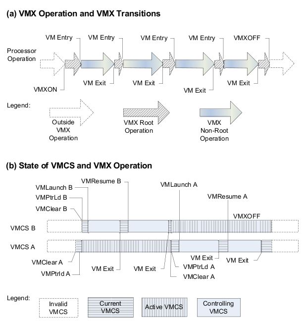
processor may maintain any number of active VMCSs. At any given time, one
is the current VMCS:
• Software makes a VMCS active by executing VMPTRLD with the address
of the VMCS. The processor may optimize VMX operation by maintain-
ing the state of an active VMCS in memory, on the processor, or both.
Software should not make a VMCS active on more than one logical pro-
cessor. Software makes a VMCS inactive by executing VMCLEAR with
the address of the VMCS. A logical processor does not use an inactive
VMCS or maintain its state on the processor.
• Software makes a VMCS current by executing VMPTRLD with the ad-
dress of the VMCS; that address is loaded into the current-VMCS pointer.
VMX instructions VMLAUNCH, VMPTRST, VMREAD, VMRESUME,
and VMWRITE operate on the current VMCS. A VMCS remains current
until either software executes VMPTRLD with the address of a different
VMCS (which then becomes the current VMCS) or software executes VM-
CLEAR with the address of the current VMCS (after which there is no
current VMCS).
NOTE: This document uses the notation RAX, RIP, RSP, RFLAGS, etc.
for processor registers because most processors that support VMX operation
also support Intel 64 architecture. For processors that do not support Intel 64
architecture, this notation refers to the 32-bit forms of those registers (EAX,
EIP, ESP, EFLAGS, etc.).
92.2 Format of the VMCS region
A VMCS region comprises up to 4-KBytes.
The first 32 bits of the VMCS region contain the VMCS revision identifier.
Processors that maintain VMCS data in different formats use different VMCS
revision identifiers. These identifiers enable software to avoid using a VMCS
region formatted for one processor on a processor that uses a different format.
Software should write the VMCS revision identifier to the VMCS region before
using that region for a VMCS. The VMCS revision identifier is never written
by the processor; VMPTRLD may fail if its operand references a VMCS region
whose VMCS revision identifier differs from that used by the processor. Software
can discover the VMCS revision identifier that a processor uses by reading the
VMX capability MSR IA32 VMX BASIC.
The next 32 bits of the VMCS region are used for the VMX-abort indicator.
The contents of these bits do not control processor operation in any way. A
logical processor writes a non-zero value into these bits if a VMX abort occurs.
Software may also write into this field.
The remainder of the VMCS region is used for VMCS data (those parts of
the VMCS that control VMX non-root operation and the VMX transitions).
The format of these data is implementation-specific. To ensure proper behavior
in VMX operation, software should maintain the VMCS region and related
structures in writeback cacheable memory. Future implementations may allow
or require a different memory type. Software should consult the VMX capability
MSR IA32 VMX BASIC.
2.3 Organization of VMCS data
The VMCS data are organized into six logical groups:
• Guest-state area. Processor state is saved into the guest-state area on VM
exits and loaded from there on VM entries.
• Host-state area. Processor state is loaded from the host-state area on VM
exits.
• VM-execution control fields. These fields control processor behavior in
VMX non-root operation. They determine in part the causes of VM exits.
• VM-exit control fields. These fields control VM exits.
• VM-entry control fields. These fields control VM entries.
• VM-exit information fields. These fields receive information on VM exits
and describe the cause and the nature of VM exits. They are read-only.
The VM-execution control fields, the VM-exit control fields, and the VM-
entry control fields are sometimes referred to collectively as VMX controls.
2.4 Guest-State Area
This section describes fields contained in the guest-state area of the VMCS. As
noted earlier, processor state is loaded from these fields on every VM entry and
stored into these fields on every VM exit.
102.4.1 Guest Register State
The following fields in the guest-state area correspond to processor registers:
• Control registers CR0, CR3, and CR4 (64 bits each; 32 bits on processors
that do not support Intel 64 architecture).
• Debug register DR7 (64 bits; 32 bits on processors that do not support
Intel 64 architecture).
• RSP, RIP, and RFLAGS (64 bits each; 32 bits on processors that do not
support Intel 64 architecture).5
• The following fields for each of the registers CS, SS, DS, ES, FS, GS,
LDTR, and TR:
– Selector (16 bits).
– Base address (64 bits; 32 bits on processors that do not support In-
tel 64 architecture). The base-address fields for CS, SS, DS, and
ES have only 32 architecturally-defined bits; nevertheless, the corre-
sponding VMCS fields have 64 bits on processors that support Intel
64 architecture.
– Segment limit (32 bits). The limit field is always a measure in bytes.
– Access rights (32 bits). The format of this field is given in Table 20-2
and detailed as follows:
The base address, segment limit, and access rights compose the “hidden”
part (or “descriptor cache”) of each segment register. These data are
included in the VMCS because it is possible for a segment register’s de-
scriptor cache to be inconsistent with the segment descriptor in memory
(in the GDT or the LDT) referenced by the segment register’s selector.
Note that the value of the DPL field for SS is always equal to the logical
processor’s current privilege level (CPL).
• The following fields for each of the registers GDTR and IDTR:
– Base address (64 bits; 32 bits on processors that do not support Intel
64 architecture).
– Limit (32 bits). The limit fields contain 32 bits even though these
fields are specified as only 16 bits in the architecture.
• The following MSRs:
– IA32 DEBUGCTL (64 bits)
– IA32 SYSENTER CS (32 bits)
– IA32 SYSENTER ESP and IA32 SYSENTER EIP (64 bits; 32 bits
on processors that do not support Intel 64 architecture)
• The register SMBASE (32 bits). This register contains the base address
of the logical processor’s SMRAM image.
112.4.2 Guest Non-Register State
In addition to the register state just described, the guest-state area includes the
following fields that characterize guest state but which do not correspond to
processor registers:
• Activity state (32 bits). This field identifies the logical processor’s activity
state. When a logical processor is executing instructions normally, it is in
the active state. Execution of certain instructions and the occurrence of
certain events may cause a logical processor to transition to an inactive
state in which it ceases to execute instructions. The following activity
states are defined: (8)
1. Active. The logical processor is executing instructions normally.
2. HLT. The logical processor is inactive because it executed the HLT
instruction.
3. Shutdown. The logical processor is inactive because it incurred a
triple fault (9) or some other serious error.
4. Wait-for-SIPI. The logical processor is inactive because it is waiting
for a startup-IPI (SIPI).
• Interruptibility state (32 bits). The IA-32 architecture includes features
that permit certain events to be blocked for a period of time. For example,
execution of STI with RFLAGS.IF = 0 blocks interrupts (and, optionally,
other events) for one instruction after its execution. Another example is
that execution of a MOV to SS or a POP to SS blocks interrupts for one
instruction after its execution. This field contains information about such
blocking.
• Pending debug exceptions (64 bits; 32 bits on processors that do not
support Intel 64 architecture). IA-32 processors may recognize one or
more debug exceptions without immediately delivering them. This field
contains information about such exceptions.
• VMCS link pointer (64 bits). This field is included for future expansion.
Software should set this field to FFFFFFFF FFFFFFFFH to avoid VM-
entry failures.
2.5 Host-State Area
This section describes fields contained in the host-state area of the VMCS. As
noted earlier, processor state is loaded from these fields on every VM exit. All
fields in the host-state area correspond to processor registers:
• CR0, CR3, and CR4 (64 bits each; 32 bits on processors that do not
support Intel 64 architecture).
• RSP and RIP (64 bits each; 32 bits on processors that do not support
Intel 64 architecture).
• Selector fields (16 bits each) for the segment registers CS, SS, DS, ES,
FS, GS, and TR. There is no field in the host-state area for the LDTR
selector.
12• Base-address fields for FS, GS, TR, GDTR, and IDTR (64 bits each; 32
bits on processors that do not support Intel 64 architecture).
• The following MSRs:
– IA32 SYSENTER CS (32 bits)
– IA32 SYSENTER ESP and IA32 SYSENTER EIP (64 bits; 32 bits
on processors that do not support Intel 64 architecture).
In addition to the state identified here, some processor state components are
loaded with fixed values on every VM exit; there are no fields corresponding to
these components in the host-state area.
2.6 VM-Execution Control Fields
The VM-execution control fields govern VMX non-root operation.
2.6.1 Pin-Based VM-Execution Controls
The pin-based VM-execution controls constitute a 32-bit vector that governs the
handling of asynchronous events like interrupts (some asynchronous events cause
VM exits regardless of the settings of the pin-based VM-execution controls). For
example, if the field named ”External-interrupt exiting” is 1, external interrupts
cause VM exits. Otherwise, they are delivered normally through the guest
interrupt-descriptor table (IDT). If this control is 1, the value of RFLAGS.IF
does not affect interrupt blocking.
The other two controls are related with NMIs and Virtual NMIs
2.6.2 Processor-Based VM-Execution Controls
The processor-based VM-execution controls constitute a 32-bit vector that gov-
erns the handling of synchronous events, mainly those caused by the execution
of specific instructions1 .
This control fields allow a VMM the flexibility to specify the instructions
that cause VM exits. There are separate controls for each of the following
instructions: HLT, INVLPG, MOV CR8, MOV DR, MWAIT, RDPMC, and
RDTSC. These controls support a variety of virtualization strategies. It also
includes the ”use I/O bitmaps” and ”use MSR bitmaps” fields, which indicates
the use of these control bitmaps, and a ”use TRP shadow” field which activates
a shadow TRP maintained in a page of memory addressed by the virtual APIC
address. See figure 3 for more details.
2.6.3 Exception Bitmap
The exception bitmap is a 32-bit field that contains one bit for each exception.
When an exception occurs, its vector is used to select a bit in this field. If
the bit is 1, the exception causes a VM exit. If the bit is 0, the exception is
delivered normally through the IDT, using the descriptor corresponding to the
exception’s vector.
1 Some instructions cause VM exits regardless of the settings of the processor-based VM-
execution controls, as do task switches.
13Figure 3: Definitions of Processor-Based VM-Execution Controls
14Whether a page fault (exception with vector 14) causes a VM exit is de-
termined by bit 14 in the exception bitmap as well as the error code produced
by the page fault and two 32-bit fields in the VMCS (the page-fault error-code
mask and pagefault error-code match). See section 3 for details.
2.6.4 I/O-Bitmap Addresses
The VM-execution control fields include the 64-bit physical addresses of I/O
bitmaps A and B (each of which are 4 KBytes in size). I/O bitmap A contains
one bit for each I/O port in the range 0000H through 7FFFH; I/O bitmap B
contains bits for ports in the range 8000H through FFFFH. A logical processor
uses these bitmaps if and only if the “use I/O bitmaps” control is 1. If the
bitmaps are used, execution of an I/O instruction causes a VM exit if any bit
in the I/O bitmaps corresponding to a port it accesses is 1.
2.6.5 Time-Stamp Counter Offset
VM-execution control fields include a 64-bit TSC-offset field. If the “RDTSC
exiting” control is 0 and the “use TSC offsetting” control is 1, this field controls
executions of the RDTSC instruction and executions of the RDMSR instruction
that read from the IA32 TIME STAMP COUNTER MSR. The signed value of
the TSC offset is combined with the contents of the time-stamp counter (using
signed addition) and the sum is reported to guest software in EDX:EAX.
2.6.6 Guest/Host Masks and Read Shadows for CR0 and CR4
VM-execution control fields include guest/host masks and read shadows for
the CR0 and CR4 registers. These fields control executions of instructions
that access those registers (including CLTS, LMSW, MOV CR, and SMSW).
They are 64 bits on processors that support Intel 64 architecture and 32 bits on
processors that do not. In general, bits set to 1 in a guest/host mask correspond
to bits “owned” by the host:
• Guest attempts to set them (using CLTS, LMSW, or MOV to CR) to
values differing from the corresponding bits in the corresponding read
shadow cause VM exits. Guest reads (using MOV from CR or SMSW)
return values for these bits from the corresponding read shadow.
• Bits cleared to 0 correspond to bits “owned” by the guest; guest attempts
to modify them succeed and guest reads return values for these bits from
the control register itself.
2.6.7 CR3-Target Controls
The VM-execution control fields include a set of 4 CR3-target values and a
CR3 target count. The CR3-target values each have 64 bits on processors that
support Intel 64 architecture and 32 bits on processors that do not. The CR3-
target count has 32 bits on all processors. An execution of MOV to CR3 in VMX
non-root operation does not cause a VM exit if its source operand matches one
of these values. If the CR3-target count is n, only the first n CR3-target values
are considered; if the CR3-target count is 0, MOV to CR3 always causes a VM
exit.
15There are no limitations on the values that can be written for the CR3-
target values. VM entry fails if the CR3-target count is greater than 4. Future
processors may support a different number of CR3-target values.
2.6.8 Controls for CR8 Accesses
On processors that support Intel 64 architecture, the CR8 register can be used in
64-bit mode to access the task-priority register (TPR) of the logical processor’s
local APIC. The VMCS contains two fields that control MOV CR8 instructions
if the “use TPR shadow” VM-execution control is 1:
• Virtual-APIC page address (64 bits). This field is the physical address
of the 4-KByte virtual-APIC page. The virtual-APIC page contains the
TPR shadow, which is read and written by the MOV CR8 instructions.
The TPR shadow comprises bits 7:4 in byte 128 of the virtual-APIC page.
If the “use TPR shadow” VM-execution control is 1, the virtual-APIC
page address must be 4-KByte aligned.
• TPR threshold (32 bits). Bits 3:0 of this field determine the threshold
below which the TPR shadow (see previous item) cannot fall. A VM exit
occurs after an execution of MOV to CR8 that reduces the TPR shadow
below this value.
These fields exist only on processors that support the 1-setting of the “use
TPR shadow” VM-execution control. Note that the TPR in the local
APIC can also be accessed using memory-mapped I/O. These controls
does not affect accesses made in that way. They affect only MOV CR8
instructions.
2.6.9 MSR-Bitmap Address
On processors that support the 1-setting of the “use MSR bitmaps” VM-execution
control, the VM-execution control fields include the 64-bit physical address of
four contiguous MSR bitmaps, which are each 1-KByte in size. This field does
not exist on processors that do not support the 1-setting of that control. The
four bitmaps are:
• Read bitmap for low MSRs (located at the MSR-bitmap address). This
contains one bit for each MSR address in the range 00000000H – 00001FFFH.
The bit determines whether an execution of RDMSR applied to that MSR
causes a VM exit.
• Read bitmap for high MSRs (located at the MSR-bitmap address plus
1024). This contains one bit for each MSR address in the range C0000000H
– C0001FFFH. The bit determines whether an execution of RDMSR ap-
plied to that MSR causes a VM exit.
• Write bitmap for low MSRs (located at the MSR-bitmap address plus
2048). This contains one bit for each MSR address in the range 00000000H
– 00001FFFH. The bit determines whether an execution of WRMSR ap-
plied to that MSR causes a VM exit.
16• Write bitmap for high MSRs (located at the MSR-bitmap address plus
3072). This contains one bit for each MSR address in the range C0000000H
– C0001FFFH. The bit determines whether an execution of WRMSR ap-
plied to that MSR causes a VM exit.
2.6.10 Executive-VMCS Pointer
The executive-VMCS pointer is a 64-bit field used in the dual-monitor treat-
ment of system-management interrupts (SMIs) and system-management mode
(SMM). SMM VM exits save this field. VM entries that return from SMM use
this field.
2.7 VM-Exit Control Fields
The VM-exit control fields govern the behavior of VM exits.
2.7.1 VM-Exit Controls
The VM-exit controls constitute a 32-bit vector that governs the basic operation
of VM exits. There are a field related with the host address-space size (whether
the host should be woking in 64-bit mode after a VM exit) and a field that
indicates if the logical processor acknowledges the interrupt controller, acquiring
the interrupt’s vector, during a VM exit due to external interrupts.
2.7.2 VM-Exit Controls for MSRs
A VMM may specify lists of MSRs to be stored and loaded on VM exits.
The following VM-exit control fields determine how MSRs are stored on VM
exits:
• VM-exit MSR-store count (32 bits). This field specifies the number of
MSRs to be stored on VM exit.
• VM-exit MSR-store address (64 bits). This field contains the physical
address of the VM-exit MSR-store area. The area is a table of entries,
16 bytes per entry, where the number of entries is given by the VM-exit
MSR-store count.
The following VM-exit control fields determine how MSRs are loaded on VM
exits:
• VM-exit MSR-load count (32 bits). This field contains the number of
MSRs to be loaded on VM exit. It is recommended that this count not
exceed 512 bytes. Otherwise, unpredictable processor behavior (including
a machine check) may result during VM exit.
• VM-exit MSR-load address (64 bits). This field contains the physical
address of the VM-exit MSR-load area. The area is a table of entries,
16 bytes per entry, where the number of entries is given by the VM-exit
MSR-load count. If the VM-exit MSR-load count is not zero, the address
must be 16-byte aligned.
172.8 VM-Entry Control Fields
The VM-entry control fields govern the behavior of VM entries.
2.8.1 VM-Entry Controls
The VM-entry controls constitute a 32-bit vector that governs the basic opera-
tion of VM entries.
There is a control that determines whether the logical processor is in IA-32e
mode after VM entry, on processors that support Intel 64 architecture. Another
control determines whether the logical processor is in system-management mode
(SMM) after VM entry.
2.8.2 VM-Entry Controls for MSRs
A VMM may specify a list of MSRs to be loaded on VM entries. The following
VM-entry control fields manage this functionality:
• VM-entry MSR-load count (32 bits). This field contains the number of
MSRs to be loaded on VM entry.
• VM-entry MSR-load address (64 bits). This field contains the physical
address of the VM-entry MSR-load area. The area is a table of entries,
16 bytes per entry, where the number of entries is given by the VM-entry
MSR-load count.
2.8.3 VM-Entry Controls for Event Injection
VM entry can be configured to conclude by delivering an event through the
guest IDT (after all guest state and MSRs have been loaded). This process is
called event injection and is controlled by the following three VM-entry control
fields:
• VM-entry interruption-information field (32 bits). This field provides de-
tails about the event to be injected:
– The vector (bits 7:0) determines which entry in the IDT is used.
– The interruption type (bits 10:8) determines details of how the in-
jection is performed. It could be an external interrupt, a NMI, a
hardware exception, a software interrupt, etc.
In general, a VMM should use the type hardware exception for all
exceptions other than breakpoint exceptions and overflow exceptions;
it should use the type software exception for those.
– For exceptions, the deliver-error-code bit (bit 11) determines whether
delivery pushes an error code on the guest stack.
– VM entry injects an event if and only if the valid bit (bit 31) is 1.
• VM-entry exception error code (32 bits). This field is used if and only if
the valid bit (bit 31) and the deliver-error-code bit (bit 11) are both set
in the VM-entry interruption-information field.
18• VM-entry instruction length (32 bits). For injection of events whose type
is software interrupt, software exception, or privileged software exception,
this field is used to determine the value of RIP that is pushed on the stack.
2.9 VM-Exit Information Fields
The VMCS contains a section of read-only fields that contain information about
the most recent VM exit.
2.9.1 Basic VM-Exit Information
The following VM-exit information fields provide basic information about a VM
exit:
• Exit reason (32 bits). This field encodes the reason for the VM exit.
– Bits 15:0 provide basic information about the cause of the VM exit
(if bit 31 is clear) or of the VM-entry failure (if bit 31 is set).
– Bit 29 is set if and only if the processor was in VMX root operation
at the time the VM exit occurred. This can happen only for SMM
VM exits.
– Because some VM-entry failures load processor state from the host-
state area, software must be able to distinguish such cases from true
VM exits. Bit 31 is used for that purpose.
• Exit qualification (64 bits; 32 bits on processors that do not support Intel
64 architecture). This field contains additional information about the
cause of VM exits due to the following: debug exceptions; page-fault
exceptions; start-up IPIs (SIPIs); task switches; INVLPG; VMCLEAR;
VMPTRLD; VMPTRST; VMREAD; VMWRITE; VMXON; control-register
accesses; MOV DR; I/O instructions; and MWAIT. The format of the field
depends on the cause of the VM exit.
2.9.2 Information for VM Exits Due to Vectored Events
Event-specific information is provided for VM exits due to the following vectored
events: exceptions (including those generated by the instructions INT3, INTO,
BOUND, and UD2); external interrupts that occur while the “acknowledge
interrupt on exit” VM-exit control is 1; and non-maskable interrupts (NMIs).
This information is provided in the following fields:
• VM-exit interruption information (32 bits). This field receives basic infor-
mation associated with the event causing the VM exit, like the vector of
interruption or exception, the type of the interruption (external interrupt,
NMI, software exception, etc), validity of error code, etc.
• VM-exit interruption error code (32 bits). For VM exits caused by hard-
ware exceptions that would have delivered an error code on the stack, this
field receives that error code.
192.9.3 Information for VM Exits Due to Instruction Execution
The following fields are used for VM exits caused by attempts to execute certain
instructions in VMX non-root operation:
• VM-exit instruction length (32 bits). For VM exits resulting from instruc-
tion execution, this field receives the length in bytes of the instruction
whose execution led to the VM exit.
• Guest linear address (64 bits; 32 bits on processors that do not support
Intel 64 architecture). This field is used in the following cases:
– VM exits due to attempts to execute LMSW with a memory operand.
– VM exits due to attempts to execute INS or OUTS.
– VM exits due to system-management interrupts (SMIs) that arrive
immediately after retirement of I/O instructions.
• VMX-instruction information (32 bits). For VM exits due to attempts to
execute VMCLEAR, VMPTRLD, VMPTRST, VMREAD, VMWRITE,
or VMXON, this field receives details about the instruction that caused
the VM exit.
3 VMX non-root operation
In a virtualized environment using VMX, the guest software stack typically
runs on a logical processor in VMX non-root operation. This mode of opera-
tion is similar to that of ordinary processor operation outside of the virtualized
environment.
This section describes the differences between VMX non-root operation and
ordinary processor operation with special attention to causes of VM exits (which
bring a logical processor from VMX non-root operation to root operation).
3.1 Instructions that cause VM exits
Certain instructions may cause VM exits if executed in VMX non-root opera-
tion. Unless otherwise specified, such VM exits are “fault-like,” meaning that
the instruction causing the VM exit does not execute and no processor state is
updated by the instruction.
3.1.1 Instructions That Cause VM Exits Unconditionally
The following instructions cause VM exits when they are executed in VMX non-
root operation: CPUID, INVD, MOV from CR3. This is also true of instructions
introduced with VMX, which include: VMCALL,2 VMCLEAR, VMLAUNCH,
VMPTRLD, VMPTRST, VMREAD, VMRESUME, VMWRITE, VMXOFF,
and VMXON.
203.1.2 Instructions That Cause VM Exits Conditionally
Certain instructions cause VM exits in VMX non-root operation depending on
the setting of the VM-execution controls. The following instructions can cause
“fault-like” VM exits based on the conditions described:
• CLTS. The CLTS instruction causes a VM exit if the bits in position 3
(corresponding to CR0.TS) are set in both the CR0 guest/host mask and
the CR0 read shadow.
• HLT. The HLT instruction causes a VM exit if the “HLT exiting” VM-
execution control is 1.
• IN, INS/INSB/INSW/INSD, OUT, OUTS/OUTSB/OUTSW/OUTSD. The
behavior of each of these instructions is determined by the settings of the
“unconditional I/O exiting” and “use I/O bitmaps” VM-execution con-
trols:
– If both controls are 0, the instruction executes normally.
– If the “unconditional I/O exiting” VM-execution control is 1 and the
“use I/O bitmaps” VM-execution control is 0, the instruction causes
a VM exit.
– If the “use I/O bitmaps” VM-execution control is 1, the instruction
causes a VM exit if it attempts to access an I/O port corresponding
to a bit set to 1 in the appropriate I/O bitmap. If an I/O operation
“wraps around” the 16-bit I/O-port space (accesses ports FFFFH
and 0000H), the I/O instruction causes a VM exit (the “uncondi-
tional I/O exiting” VM-execution control is ignored if the “use I/O
bitmaps” VM-execution control is 1).
• INLVPG. The INLVPG instruction causes a VM exit if the “INLVPG
exiting” VM-execution control is 1.
• LMSW. In general, the LMSW instruction causes a VM exit if it would
write, for any bit set in the low 4 bits of the CR0 guest/host mask, a value
different than the corresponding bit in the CR0 read shadow. Note that
LMSW never clears bit 0 of CR0 (CR0.PE). Thus, LMSW causes a VM
exit if either of the following are true:
– The bits in position 0 (corresponding to CR0.PE) are set in both the
CR0 guest/mask and the source operand, and the bit in position 0
is clear in the CR0 read shadow.
– For any bit position in the range 3:1, the bit in that position is set
in the CR0 guest/mask and the values of the corresponding bits in
the source operand and the CR0 read shadow differ.
• MONITOR. The MONITOR instruction causes a VM exit if the “MON-
ITOR exiting” VM-execution control is 1.
• MOV from CR8. The MOV from CR8 instruction (which can be exe-
cuted only in 64-bit mode on processors that support Intel 64 architec-
ture) causes a VM exit if the “CR8-store exiting” VM-execution control
is 1.
21• MOV to CR0. The MOV to CR0 instruction causes a VM exit unless the
value of its source operand matches, for the position of each bit set in the
CR0 guest/host mask, the corresponding bit in the CR0 read shadow. (If
every bit is clear in the CR0 guest/host mask, MOV to CR0 cannot cause
a VM exit.)
• MOV to CR3. The MOV to CR3 instruction causes a VM exit unless
the value of its source operand is equal to one of the CR3-target values
specified in the VMCS. Note that, if the CR3-target count is n, only the
first n CR3-target values are considered; if the CR3-target count is 0,
MOV to CR3 always causes a VM exit.
• MOV to CR4. The MOV to CR4 instruction causes a VM exit unless the
value of its source operand matches, for the position of each bit set in the
CR4 guest/host mask, the corresponding bit in the CR4 read shadow.
• MOV to CR8. The MOV to CR8 instruction (which can be executed only
in 64-bit mode on processors that support Intel 64 architecture) causes a
VM exit if the “CR8-load exiting” VM-execution control is 1. Note that, if
this control is 0, the behavior of the MOV to CR8 instruction is modified
if the “use TPR shadow” VM-execution control is 1 and it may cause a
trap-like VM exit.
• MOV DR. The MOV DR instruction causes a VM exit if the “MOV-DR
exiting” VM-execution control is 1.
• MWAIT. The MWAIT instruction causes a VM exit if the “MWAIT ex-
iting” VM-execution control is 1.
• PAUSE. The PAUSE instruction causes a VM exit if the “PAUSE exiting”
VM-execution control is 1.
• RDMSR. The RDMSR instruction causes a VM exit if any of the following
are true:
– The “use MSR bitmaps” VM-execution control is 0.
– The value of RCX is not in the range 00000000H – 00001FFFH or
C0000000H – C0001FFFH.
– The value of RCX is in the range 00000000H – 00001FFFH and the
nth bit in read bitmap for low MSRs is 1, where n is the value of
RCX.
– The value of RCX is in the range C0000000H – C0001FFFH and the
nth bit in read bitmap for high MSRs is 1, where n is the value of
RCX & 00001FFFH.
• RDPMC. The RDPMC instruction causes a VM exit if the “RDPMC
exiting” VM-execution control is 1.
• RDTSC. The RDTSC instruction causes a VM exit if the “RDTSC exit-
ing” VM-execution control is 1.
• RSM. The RSM instruction causes a VM exit if executed in system-
management mode (SMM).
22• WRMSR. The WRMSR instruction causes a VM exit if any of the follow-
ing are true:
– The “use MSR bitmaps” VM-execution control is 0.
– The value of RCX is not in the range 00000000H – 00001FFFH or
C0000000H – C0001FFFH.
– The value of RCX is in the range 00000000H – 00001FFFH and the
nth bit in write bitmap for low MSRs is 1, where n is the value of
RCX.
– The value of RCX is in the range C0000000H – C0001FFFH and the
nth bit in write bitmap for high MSRs is 1, where n is the value of
RCX & 00001FFFH.
• The MOV to CR8 instruction (which can be executed only in 64-bit mode
on processors that support Intel 64 architecture) may cause a “trap-like”
VM exit. This means that the instruction completes before the VM exit
occurs and that processor state is updated by the instruction (for example,
the value of RIP saved in the guest-state area of the VMCS references the
next instruction). Specifically, a VM exit occurs after execution of MOV
to CR8 if the following are true:
– The “CR8-load exiting” VM-execution control is 0.
– The “use TPR shadow” VM-execution control is 1.
– The execution of MOV to CR8 reduces the value of the TPR shadow
below that of the TPR threshold.
3.2 Other causes of VM exits
In addition to VM exits caused by instruction execution, the following events
can cause VM exits:
• Exceptions. Exceptions (faults, traps, and aborts) cause VM exits based
on the exception bitmap. If an exception occurs, its vector (in the range
0–31) is used to select a bit in the exception bitmap. If the bit is 1, a VM
exit occurs; if the bit is 0, the exception is delivered normally through the
guest IDT. This use of the exception bitmap applies also to exceptions
generated by the instructions INT3, INTO, BOUND, and UD2.
Page faults (exceptions with vector 14) are specially treated. When a page
fault occurs, a logical processor consults (1) bit 14 of the exception bitmap;
(2) the error code produced with the page fault [PFEC]; (3) the page-
fault error-code mask field [PFEC MASK]; and (4) the page-fault error-
code match field [PFEC MATCH]. It checks if PFEC & PFEC MASK
= PFEC MATCH. If there is equality, the specification of bit 14 in the
exception bitmap is followed (for example, a VM exit occurs if that bit is
set). If there is inequality, the meaning of that bit is reversed (for example,
a VM exit occurs if that bit is clear). Thus, if the design requires VM exits
on all page faults, software can set bit 14 in the exception bitmap to 1 and
set the page-fault error-code mask and match fields each to 00000000H. If
the design does not require VM exits on page faults, software could set bit
2314 in the exception bitmap to 1, set the page-fault error-code mask field to
00000000H, and set the page-fault error-code match field to FFFFFFFFH.
• External interrupts. An external interrupt causes a VM exit if the “exter-
nal interrupt exiting” VM-execution control is 1. Otherwise, the interrupt
is delivered normally through the IDT. (If a logical processor is in the
shutdown state or the wait-for-SIPI state, external interrupts are blocked.
The interrupt is not delivered through the IDT and no VM exit occurs.)
• Non-maskable interrupts (NMIs). An NMI causes a VM exit if the “NMI
exiting” VM-execution control is 1. Otherwise, it is delivered using de-
scriptor 2 of the IDT. (If a logical processor is in the wait-for-SIPI state,
NMIs are blocked. The NMI is not delivered through the IDT and no VM
exit occurs.)
• INIT signals. INIT signals cause VM exits. A logical processor performs
none of the operations normally associated with these events. Such exits
do not modify register state or clear pending events as they would outside
of VMX operation. (If a logical processor is in the wait-for-SIPI state,
INIT signals are blocked. They do not cause VM exits in this case.)
• Start-up IPIs (SIPIs). SIPIs cause VM exits. If a logical processor is
not in the wait-for-SIPI activity state when a SIPI arrives, no VM exit
occurs and the SIPI is discarded. VM exits due to SIPIs do not perform
any of the normal operations associated with those events: they do not
modify register state as they would outside of VMX operation. (If a logical
processor is not in the wait-for-SIPI state, SIPIs are blocked. They do not
cause VM exits in this case.)
• Task switches. Task switches are not allowed in VMX non-root operation.
Any attempt to effect a task switch in VMX non-root operation causes a
VM exit.
In addition, there is one control that causes VM exits based on the readiness
of guest software to receive an external interrupt:
• If the “interrupt-window exiting” VM-execution control is 1, a VM exit
occurs before execution of any instruction if RFLAGS.IF = 1 and there is
no blocking of events by STI or by MOV SS. Such a VM exit occurs im-
mediately after VM entry if the above conditions are true. Non-maskable
interrupts (NMIs) and higher priority events take priority over VM exits
caused by this control. VM exits caused by this control take priority over
external interrupts and lower priority events.
• If the “NMI-window exiting” VM-execution control is 1, a VM exit occurs
before execution of any instruction if there is no virtual-NMI blocking and
there is no blocking of events by MOV SS. (A logical processor may also
prevent such a VM exit if there is blocking of events by STI.) Such a VM
exit occurs immediately after VM entry if the above conditions are true.
Debug-trap exceptions and higher priority events take priority over VM
exits caused by this control. VM exits caused by this control take priority
over nonmaskable interrupts (NMIs) and lower priority events.
24You can also read