Manual - Expert Net Control 2302 2019 GUDE Systems GmbH Manual Ver. 1.0.3 from Firmware Ver. 1.0
←
→
Page content transcription
If your browser does not render page correctly, please read the page content below
Manual

Expert Net Control 2302

                          © 2019 GUDE Systems GmbH
                                      Manual Ver. 1.0.3
                                 from Firmware Ver. 1.0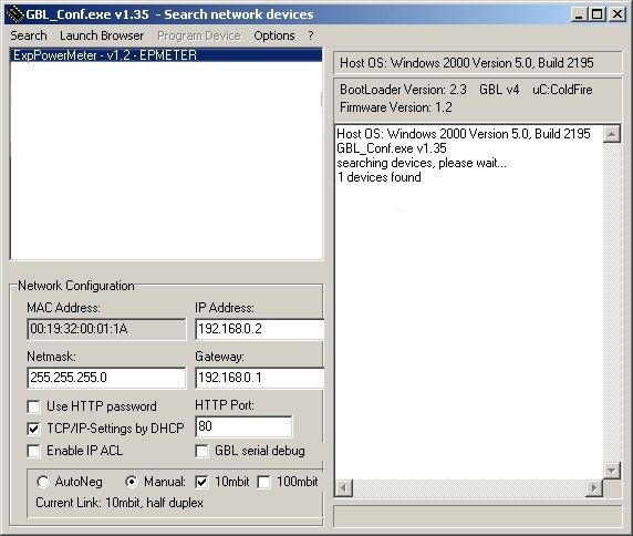
2

Expert Net Control 2301   © 2019 GUDE Systems GmbH

Table of contents

1.       Device Description                                                                                                                     5
   1.1          Security Advice ....................................................................................................... 6
   1.2          Content of Delivery ................................................................................................. 6
   1.3          Description ............................................................................................................. 6
   1.4     Installation ............................................................................................................. 7
     1.4.1      Connection Example ................................................................................................ 8
   1.5     Technical Specifications ........................................................................................ 10
   1.6          Sensor .................................................................................................................. 10

2.       Operating                                                                                                                            13
   2.1          Operating the device directly ................................................................................ 14
   2.2          Control Panel ........................................................................................................ 14
   2.3     Maintenance ........................................................................................................ 16
     2.3.1    Maintenance Page ................................................................................................. 18
     2.3.2    Configuration Management .................................................................................. 19
     2.3.3    Bootloader Activation ............................................................................................ 20

3.       Configuration                                                                                                                        23
   3.1     Output Ports ......................................................................................................... 24
     3.1.1     Watchdog ............................................................................................................... 25
   3.2     Input Ports ............................................................................................................ 27
   3.3          Ethernet ............................................................................................................... 27
     3.3.1          IP Address ............................................................................................................... 28
     3.3.2          IP ACL ..................................................................................................................... 29
     3.3.3          HTTP ....................................................................................................................... 30
   3.4          Protocols .............................................................................................................. 31
     3.4.1          Console ................................................................................................................... 31
     3.4.2          Syslog ..................................................................................................................... 32
     3.4.3          SNMP ...................................................................................................................... 33
     3.4.4          Radius ..................................................................................................................... 34
     3.4.5          Modbus TCP ........................................................................................................... 35
   3.5          Sensors ................................................................................................................. 36
     3.5.1          Port Switching ........................................................................................................ 37
   3.6          E-Mail ................................................................................................................... 38
   3.7          Front Panel ........................................................................................................... 39

4.       Specifications                                                                                                                       40
   4.1          IP ACL ................................................................................................................... 41
   4.2          IPv6 ...................................................................................................................... 41
   4.3          Radius ................................................................................................................... 42

     3

Expert Net Control 2301                                                                                                        © 2019 GUDE Systems GmbH
Table of contents

   4.4          Automated Access ................................................................................................ 42
   4.5     SNMP ................................................................................................................... 43
     4.5.1      Device MIB 2302 .................................................................................................... 45
   4.6     SSL ........................................................................................................................ 46
   4.7     Console ................................................................................................................. 48
     4.7.1    Console Cmd 2302 ................................................................................................. 52
   4.8     Modbus TCP ......................................................................................................... 57
   4.9          Messages .............................................................................................................. 61

5.       Support                                                                                                                        63
   5.1          Data Security ........................................................................................................ 64
   5.2          Contact ................................................................................................................. 64
   5.3          Declaration of Conformity ..................................................................................... 65
   5.4          FAQ ...................................................................................................................... 65

Index                                                                                                                                   66

                                                                                                                                          4

Expert Net Control 2301                                                                                                   © 2019 GUDE Systems GmbH
Device Description
Device Description

1           Device Description
1.1         Security Advice

            · The device must be installed only by qualified personnel according to the following
              installation and operating instructions.
            · The manufacturer does not accept responsibility in case of improper use of the
              device and particularly any use of equipment that may cause personal injury or ma-
              terial damage.
            · The device contains no user-maintainable parts. All maintenance has to be per-
              formed by factory trained service personnel.
            · Connect the device to the mains (230V AC) or to an AC Adaptor (10V to 24V AC,
              12V to 28V DC, at 4 watts of power). Under no circumstances should the unit be fed
              with the mains and the AC Adaptor at the same time!
            · The device is intended for indoor use only. Do NOT install them in an area where ex-
              cessive moisture or heat is present.
            · Because of safety and approval issues it is not allowed to modify the device without
              our permission.
            · The device is NOT a toy. It has to be used or stored out or range of children.
            · Care about packaging material. Plastics has to be stored out of range of children.
              Please recycle the packaging materials.
            · In case of further questions, about installation, operation or usage of the device,
              which are not clear after reading the manual, please do not hesitate to ask our sup-
              port team.

1.2         Content of Delivery

            The package includes:

            · Expert Net Control 2302
            · CD-ROM with manual

1.3         Description

            The Expert Net Control 2302 can switch 4 different relay outputs and monitor 8 pass-
            ive signal inputs. The device has the following features:

            · 4 switchable, potential-free relay ouputs, switching voltage 230 V AC 16 A / 24 V DC,
              10 A
            · Relays dispose of high contact reliability also at very small loads
            · 8 passive inputs for monitoring NO and NC devices, e.g. door contacts, smoke de-
              tectors etc.
            · Stop input to switch-off of all relais
            · Status and Power-up delay (0...9999 seconds) adjustable individually for each relay
              port after power blackout
            · Programmable turn-on/turn-off sequence
            · 4-channel watchdog, an individual watchdog (ICMP/TCP) can be assigned for each
              relay output
            · Operation with 230 V AC or 24 V DC voltage

                                                                                                              6

Expert Net Control 2301                                                                          © 2019 GUDE Systems GmbH
Device Description
· Optional sensor for environmental monitoring (temperature, humidity and air pres-
sure)
· Firmware update via Ethernet during operation
· Comfortable configuration by web browser, Windows or Linux tool
· Generation of messages (e-mail, Syslog and SNMP traps) and relay switching de-
pending on input change, resp. external sensors
· IPv6 ready
· HTTP/HTTPS, e-mail (SSL, STARTTLS), DHCP, Syslog
· SNMPv1, v2c, v3 (Get/Traps)
· Modbus TCP Support
· Console Commands with telnet support and serial interface
· TLS 1.0, 1.1, 1.2
· IP Access Control List
· Low internal power consumption
· Android and iOS app Gude Control allows access from anywhere
· Developed and manufactured in Germany
1.4 Installation
1. 230V AC power supply
2. Four relay outputs ( potential-free)
3. Ethernet connector (RJ45)
4. Sensor connector (RJ45)
5. Activity LED (Input) for digital inputs
6. 4 status LED for relay outputs
7. Status LED
7
Expert Net Control 2301 © 2019 GUDE Systems GmbHDevice Description
8. Button for Select and OK
9. Alternative low power supply LV PWR (Low Voltage PoWeR)
10. Eight passive inputs (with GND ( ) for 2 inputs each)
11. Stop input (with GND ( )) to switch-off of all relais
Start-up the device
· Connect the device to the mains (230V AC) or to an AC Adaptor (10V to 24V AC,
12V to 28V DC, at 4 watts of power). Under no circumstances should the unit be fed
with the mains and the AC Adaptor at the same time!
· Plug the network cable into the Ethernet socket (RJ45) .
· Connect the relay to the loads that should be be operated.
· Make contact between the lines to be monitored and the digital inputs. To close an
input circuit there has to be a connection between a ground pin ( ) and the respect-
ive input pin has to be made.
· Connect the sensor (if any) to the device.
1.4.1 Connection Example
Here an example of a block diagram in which the device is supplied with 230V AC, and
four AC loads (L1 - L4) are connected. In addition, the inputs are joined to eight
switches (S1 - S8), and the stop input is connected to the push-button PB1.
8
Expert Net Control 2301 © 2019 GUDE Systems GmbHDevice Description 9 Expert Net Control 2301 © 2019 GUDE Systems GmbH
Device Description

1.5         Technical Specifications

               Interfaces                    1 x Ethernet port (RJ45)
                                             1 x Connector for mains supply (230V AC)
                                             1 x Connector for AC Adaptor (12V DC, 0,5A). 12V DC power
                                            supply
                                             12 x screw terminal with 8 inputs and 4 x GND
                                             8 x screw terminal with 4 make contacts (230V AC 16A,
                                                 24V DC 10 A)
                                             1 x RJ45 for external sensor
               Network connectivity          10/100 MBit/s 10baseT Ethernet
               Protocols                     TCP/IP, HTTP/HTTPS, SNMP v1/v2c/v3,
                                             SNMP traps, Syslog, E-Mail (SMTP)
               Power Supply                  internal power supply (230V AC)
                                             alternative: 10V to 24V AC, 12V to 28V DC (at 4 watts of
                                            power)
               Environment
               · Operating temperature        0°C to 50°C
               · Storage temperature          -15°C to 60°C
               · Humidity                     10% to 85%
               Case                           plastics black
               Measurements                   105mm x 70mm x 90mm (L x H x D)
               Weight                         approx. 300g

1.6         Sensor

            One external sensor can be connected to the Expert Net Control 2302. The following
            sensors are currently available

                                  Humidity/Temperature Sensor 7102 (End-of-Life)
             Cable length
             Connector                         RJ45
             temperature range                 -20°C to +80°C, ±0,5°C (maximum) and ±0,3°C (typical)

             air humidity range                0-100%, ±3% (maximum) and ±2% (typical)
             (non-condensing))

                                                                                                                    10

Expert Net Control 2301                                                                                 © 2019 GUDE Systems GmbH
Device Description
Product Name 7101 7104 7105 7106
Cable length
Connector RJ45 RJ45 RJ45 RJ45
temperature range -20°C to +80°C at -20°C to +80°C at -20°C to +80°C at -20°C to +80°C at
±2°C (maximum) ±2°C (maximum) ±2°C (maximum) ±2°C (maximum)
and ±1°C (typical) and ±1°C (typical) and ±1°C (typical) and ±1°C (typical)
air humidity range - - 0-100%, ±3% 0-100%, ±3%
(non-condensing) (maximum) and (maximum) and
±2% (typical) ±2% (typical)
air pressure range - - - ± 1 hPa (typical)
(full) at 300 ... 1100
hPa, 0 ... +40 °C
air pressure range - - - ± 1.7 hPa (typical)
(ext) at 300 ... 1100
hPa, -20 ... 0 °C
Protection IP68 - - -
11
Expert Net Control 2301 © 2019 GUDE Systems GmbHDevice Description
Product Name 7201 7202
Cable length - -
Connector RJ45 RJ45
temperature range -20°C to +80°C at ±2°C (max- -20°C to +80°C at ±2°C (max-
imum) and ±1°C (typical) imum) and ±1°C (typical)
air humidity range - 0-100%, ±3% (maximum) and
(non-condensing) ±2% (typical)
The sensors are detected automatically after connection. The sensor values are
displayed directly on the "Control Panel" website:
A click on the link in the "Name" column opens the display of the Min and Max values.
The values in a column can be reset using the "Reset" button. The "Reset" button in
the name column deletes all stored Min and Max values.
12
Expert Net Control 2301 © 2019 GUDE Systems GmbHOperating
Operating

2           Operating
2.1         Operating the device directly

            Port Switching
            The current status of the output is indicated by the color of the LED. A red LED indic-
            ates that the output is off, green shows that the output is on. On the device are the but-
            tons "select" and "ok". If you press "select", the LED will blink for the first output, ie the
            output is selected. Press "select" again to select the next output. Hold down the button
            "ok" for two seconds, then the status of the selected output is toggled.

            Status-LED
            The Status LED shows the different states of the device:

            · red: The device is not connected to the Ethernet.
            · orange: The device is connected to the Ethernet and waits for data from the DHCP
              server.
            · green: The device is connected to the Ethernet and the TCP/IP settings are alloc-
              ated.
            · periodic blinking: The device is in Bootloader mode.

2.2         Control Panel

            Access the web interface: http://"IP-address" and log-in.

                                                                                                                    14

Expert Net Control 2301                                                                                 © 2019 GUDE Systems GmbH
Operating
The web page provides an overview of the switching state, as well as the external
sensor, provided that it is connected. When a single port is clicked at the Expert Net
Control 2302, a panel with buttons to control a single port appear:
The Port icon is green when the relay is closed, or red in the open state. An additional
small clock icon indicates that a timer is active. Timer can be activated by delay, reset
or batch mode.
An activated Watchdog is represented by an eye icon. An "X" means, that the address
that should be observed, could not be resolved. Two circular arrows show a booting
status.
The ports can be switched manually with the "On" and "Off" buttons. If the port is
turned on, it can be turned off by pressing the "Reset" button, until after a delay it turns
itself on again. The delay time is determined by the parameter Reset Duration, which is
described in the chapter "Configuration - Output Ports 24 ". The "Close" button dis-
solves the panel again.
Batchmode
15
Expert Net Control 2301 © 2019 GUDE Systems GmbHOperating
Each individual port can be set for a selectable period of time to the state "switch on"
or "switch off". After the selected time they are automatically switched to the second
preselected state.
Optionally the device can be switched via a Perl script or external tools like wget. More
information is available on our support wiki at www.gude.info/wiki.
The website contains a status overview of all passive signal inputs, the time since the
last change, and a counter of switching changes. The name and text for a logical state
of each input can be configured in the chapter Configuration-Input Ports 27 .
2.3 Maintenance
The actual device generation with IPv6 and SSL allows all maintenance functions in
the web interface to be carried out on the Maintenance Page 18 .
Maintenance in the web interface
The following functions are available from the maintenance web page:
· Firmware Update
· Change the SSL certificate
· Load and save the configuration
· Restart the device
· Factory Reset
· Jump into the Bootloader
· Delete the DNS cache
Upload Firmware, Certificate or Configuration
16
Expert Net Control 2301 © 2019 GUDE Systems GmbHOperating
On the Maintenance Page 18 , select the required file with "Browse .." in the sections
"Firmware Update", "SSL Certificate Upload" or "Config Import File Upload" and press
"Upload". The file is now transferred to the update area of the device and the contents
are checked. Only now, pressing the "Apply" button will permanently update the data,
or abort with "Cancel".
Only one upload function can be initiated with a reboot, eg. you cannot transmit
firmware and configuration at the same time.
If after a firmware update, the web page is not displayed correctly anymore, this
may be related to the interaction of Javascript with an outdated browser cache. If a
Ctrl-F5 does not help, it is recommended that you manually delete the cache in the
browser options. Alternatively, you can test start the browser in "private mode".
Actions in Bootloader mode
If the web interface of the device is no longer accessible, the device can be put into
Bootloader mode (see chapter Bootloader activation 20 ). The following functions can
be executed using the GBL_Conf.exe application:
· Set IPv4 address, net-mask and gateway
· Turn HTTP password on and off
· Turn IP-ACL on and off
· Factory Reset
· Jump into the bootloader (can be switched on and off)
· Restart the device
For devices with relays, entering or exiting the bootloader mode does not change
the state of the relays as long as the operating voltage is maintained.
The GBL_Conf.exe program is available free of charge on our website www.gude.info
and can also be found on the enclosed CD-ROM.
Interface GBL_Conf
17
Expert Net Control 2301 © 2019 GUDE Systems GmbHOperating
To check the network settings with GBL_Conf.exe, start the program and choose "All
Devices" in the "Search" menu. From the list select the appropriate device. The lower
part of the left half of the window now shows the current network settings of the device.
If the IP address is displayed with the default settings (192.168.0.2), either no DHCP
server is present on the network, or there could be no free IP address assigned to it.
· Activate the Bootloader Mode (see Chapter Bootloader Mode) and choose in menu
"Search" the item "Bootloader-Mode Devices only"
· Enter the desired settings in the edit window and save them with "Save Config".
· Deactivate the boot loader mode for the changes to take effect. Select again "All
Devices" in the "Search" menu of GBL_Conf.exe.
The new network configuration is now displayed.
Factory Reset
The device can be reset to the factory default via the web interface from the Mainten-
ance Page 18 or from the Bootloader mode (see chapter Bootloader activation 20 ). All
TCP/IP settings are reset in this operation.
If a unit is set to factory defaults, an uploaded certificate or updated firmware will
be preserved.
2.3.1 Maintenance Page
This section provides access to important functions such as Firmware Update or Re-
start Device. It is advisable to set an HTTP password for this reason.
Firmware Update: Start a firmware update.
18
Expert Net Control 2301 © 2019 GUDE Systems GmbHOperating
SSL Certificate Upload: Saves your own SSL certificate. See chapter "SSL 47 " for the
generation of a certificate in the right format.
Config Import File Upload: Loads a new configuration from a text file. To apply the new
configuration, a "Restart Device" must be executed after the "Upload".
Config File Export: Saves the current configuration in a text file.
Saving the configuration should only be carried out in an SSL connection, since it
contains sensitive password information (even if it is encrypted or hashed).
Restart Device: Restarts the device without changing the status of the relays.
Some functions such as a firmware update or changing of the IP-address and
HTTP settings require a restart of the device. A jump to the boot loader or a restart of
the device lead by no means to a change of the relay states.
Restore Fab Settings and Restart Device: Performs a restart and resets the device to
factory default 21 .
Enter Bootloader Mode: Jumps into bootloader mode, where additional settings can be
made with GBL_Conf.exe.
Flush DNS Cache: All entries in the DNS cache are discarded and address resolutions
are requested again.
2.3.2 Configuration Management
The device configuration can be saved and restored in the maintenance area 18 .
The "Config File Export" function can be used to save the current configuration as a
text file. The syntax used in the configuration file corresponds to the commands of the
Telnet console. If the configuration of a device is to be restored from a text file, load
the file with "Upload" and restart the device with "Restart Device".
Saving the configuration should only be carried out in an SSL connection, since it
contains sensitive password information (even if it is encrypted or hashed). For the
same reasons, it is advisable to carefully handle the generated configuration files when
archiving.
Editing the configuration file
It is possible to customize a saved configuration file with a text editor for your own
needs. For example, one scenario would be to use a script language to automate the
creation of many customized versions of a configuration, then equip a large number of
devices with an individualized configuration. Also Upload and restart with CGI com-
mands can be done in scripting languages. With use of the comment sign "#" you can
quickly hide single commands or add personal notes.
19
Expert Net Control 2301 © 2019 GUDE Systems GmbHOperating
If you modify a configuration file manually, it is not always clear which limits are allowed
for parameters. After uploading and restarting, commands with invalid parameters are
ignored. Therefore, the generated configuration includes comments describing the
boundaries of the parameters. Where "range:" refers to a numeric value, and "len:" to a
text parameter. E.g:
email auth set 0 #range: 0..2
email user set "" #len: 0..100
The command "system fabsettings" from the beginning of a generated configuration
file brings the device into the factory state, and then executes the individual commands
that modify the configuration state. It may be desirable to make the changes relative to
the current configuration, and not out of the factory state. Then the "system fabset-
tings" should be removed.
No output of default values
The configuration file contains (with exceptions) only values which differ from the de-
fault. The command "system fabsettings" (go to the factory state) from the beginning of
a generated configuration file should not be removed, otherwise the device can get in-
completely configured.
Configuration via Telnet
The configuration files can in principle also be transferred in a Telnet session, but then
the settings are changed during operation, and not completely when restarting, as it
would have been the case with an upload. It can happen that events are triggered at
the same time as the device is configured. One should therefore:
a) disable the function
b) completely parametrize
c) reactivate the function
An example:
email enabled set 0
email sender set "" #len: 0..100
email recipient set "" #len: 0..100
email server set "" #len: 0..100
email port set 25
email security set 0 #range: 0..2
email auth set 0 #range: 0..2
email user set "" #len: 0..100
email passwd hash set "" #len: 0..100
email enabled set 1 #range: 0..1
2.3.3 Bootloader Activation
The configuration of the device from the application "GBL_Conf.exe" is only possible, if
the device is in Bootloader Mode.
Activation of the Bootloader Mode
1) via push button:
· Hold both buttons for 3 seconds
20
Expert Net Control 2301 © 2019 GUDE Systems GmbHOperating
2) or
· Remove the power supply
· Hold down the "Select" button. If the push button is recessed, use a pin or paper clip
· Connect the operating voltage
3) by Software: (only if "Enable FW to BL" was previously activated in the
"GBL_Conf.exe" application)
· Start the "GBL_Conf.exe" program
· Do a network search with the "Search" menu action
· Activate in menu "Program Device" the item "Enter Bootloader"
4) via web interface:
Press "Enter Bootloader Mode" on the maintenance 18 web page.
Whether the device is in Bootloader mode, is indicated by the flashing of the status
LED, or it is shown in "GBL_Conf.exe" application after a renewed device search (ap-
pendix "BOOT-LDR" after the device name). In Bootloader mode the program
"GBL_Conf.exe" can disable the password and the IP ACL, perform a firmware update,
and restore the factory settings.
For devices with relays, entering or exiting the bootloader mode does not change
the state of the relays as long as the operating voltage is maintained.
Abandonment of the Bootloader Mode
1) via push button:
· Hold both buttons for 3 seconds (only if the device has 2 buttons)
2) or
· Remove and connect the power supply without operating a button
3) by Software:
· Start the "GBL_Conf.exe" application
· Do a network search with the "Search" menu action
· In menu "Program Device" activate the item "Enter Firmware"
Factory Reset
If the device is in bootloader mode, it can always be put back to its factory default. All
TCP/IP settings are reset in this operation.
If a unit is set to factory defaults, an uploaded certificate or updated firmware will
be preserved.
1) via push button:
· Activate the Bootloader Mode of the device
· Hold down the button (or the "Select" button for devices with 2 buttons) for 6
seconds. If the push button is recessed, use a pin or paper clip
· The status LED will blink in a fast rhythm, please wait until the LED blinks slowly
21
Expert Net Control 2301 © 2019 GUDE Systems GmbHOperating
(about 5 seconds)
2) by Software:
· Activate the Bootloader Mode of the device
· "Start the GBL_Conf.exe" program
· In menu "Program Device" activate the item "Reset to Fab Settings"
· The status LED will blink in a fast rhythm, please wait until the LED blinks slowly
(about 5 seconds)
22
Expert Net Control 2301 © 2019 GUDE Systems GmbHConfiguration
Configuration

3           Configuration

            TCP/IP configuration by DHCP
            After switching on the device is scanning on the Ethernet for a DHCP server and re-
            quests an unused IP address. Check the IP address that has been assigned and ad-
            just if necessary, that the same IP address is used at each restart. To turn off DHCP
            use the software GBL_Conf.exe or use the configuration via the web interface.

            To check the network settings with GBL_Conf.exe, start the program and choose "All
            Devices" in the "Search" menu. From the list select the appropriate device. The lower
            part of the left half of the window now shows the current network settings of the device.
            If the IP address is displayed with the default settings (192.168.0.2), either no DHCP
            server is present on the network, or there could be no free IP address assigned to it.

3.1         Output Ports

            Choose Output Port to configure: This field is used to select the Output Ports to be
            configured.

            Label: You can assign a name up to 15 characters for each of the Output Ports. Using
            the name, an identification of the the device connected to the port can be facilitated.

            Start-up Monitoring
            It is important, that if necessary the condition of the Output Ports can be restored after
            a power failure. Therefore each port can be configured with Initialization status to a
            specific start-up state. This start-up sequence can be carried out delayed by the para-
            meter Initialization Delay. There is in any case a minimum one-second delay between
            switching of ports.

            Initialization status(coldstart): This is the port state (on, off, remember last state) the
            port should be set when the device is turned on. The setting "remember last state"
            saves the last manually set state of the Output Port in the EEPROM.

                                                                                                                      24

Expert Net Control 2301                                                                                   © 2019 GUDE Systems GmbH
Configuration
Initialization delay: Here can be configured how long the port should wait to switch to its
defined state after the device is turned on. The delay may last up to 8191 seconds.
This corresponds to a period of approx. two hours and 20 minutes. A value of zero
means that the initialization is off.
Repower delay: When this feature is enabled (value greater than 0), the Output Port
will switch itself on again a specified time after it has been disabled. Unlike the "Reset"
button this function applies to all switch actions, including SNMP, or an optional serial
interface.
Reset Duration: When the "Reset" button is triggered, the device turns the Output Port
off, waits for the time entered here (in seconds) and turns the Output Port on.
3.1.1 Watchdog
The watchdog feature enables to monitor various remote devices. Therefore either
ICMP pings or TCP pings are sent to the device to be monitored. If these pings are not
answered within a certain time (both the time and the number of attempts can be set),
the port is reset. This allows e.g. to automatically restart not responding server or NAS
systems. The mode IP master-slave port allows you to switch a port depending on the
availability of a remote device.
When a watchdog is activated it presents various information in the Control Panel. The
information is color-coded.
· Green text: The watchdog is active and regularly receives ping replies.
· Orange text: The watchdog is currently enabled, and waits for the first Ping re-
sponse.
· Red text: The watchdog is active and receives no ping replies anymore from the con-
figured IP address.
After the watchdog has been enabled, the display remains orange until the watchdog
receives a ping response for the first time. Only then the watchdog is activated. Even
after triggering a watchdog and a subsequent Output Port reset, the display will remain
orange until the device is rebooted and responds again to ping requests. This will pre-
vent a premature watchdog reset of the port, e.g. when a server needs a long time for
a file check.
You can monitor devices on your own network, as well as devices on an external net-
work, e.g. the operating status of a router.
25
Expert Net Control 2301 © 2019 GUDE Systems GmbHConfiguration
Enable watchdog: Enables the watchdog function for this Output Port.
Watchdog type: Here you can choose between the monitoring by ICMP pings or TCP
pings.
· ICMP Pings: The classic ping (ICMP echo request). It can be used to check the ac-
cessibility of network devices (for example, a server).
· TCP Pings: With TCP pings, you can check if a TCP port on the target device would
accept a TCP connect. Therefore a non-blocked TCP port should be selected. A
good choice would be port 80 for http or port 25 for SMTP.
TCP port: Enter the TCP port to be monitored. When using ICMP pings this is not
needed.
Hostname: The name or IP address of the monitored network device.
Ping interval: Select the frequency (in seconds) at which the ping packet is sent to
each network device to check its operating status.
Ping retries: After this number of consecutive unanswered ping requests the device is
considered inactive.
Watchdog mode: When Reset port when host down is enabled, the Output Port is
turned off and switched back on after the time set in Reset Duration. In mode Switch
off once when host down the Output Port remains disabled.
At the default setting (Infinite wait for booting host after reset) the watchdog monitors
the connected device. When there is no longer a reply after a set time, the watchdog
performs the specified action, usually a reset of the Output Port. Now the watchdog
waits until the monitored device reports again on the network. This may take several
minutes depending on the boot duration of the device. Only when the device is access-
ible from network again, the watchdog is re-armed. If the option Repeat reset on boot-
ing host after x ping timeout is enabled, this mechanism is bypassed. Now the watch-
dog is re-activated after N Ping intervals (input field ping timeouts).
When enabling the IP master-slave mode, the port is switched depending on the avail-
ability of a remote device. Depending on the configuration, the port is switched on
when the terminal is reachable, or vice versa.
The option Repeat reset on booting host after x ping timeout has the following pit-
fall: If a server, that is connected to the monitored Port is in need for a long boot pro-
cess (e.g. it is doing a file system check), the server would probably exceed the trip-
ping time of the watchdog. The server would be switched off and on again, and the file
system check is restarted. This would be repeated endlessly.
26
Expert Net Control 2301 © 2019 GUDE Systems GmbHConfiguration
3.2 Input Ports
Choose Input port to configure: This field is used to select the input port to be con-
figured.
Name: You can assign a name up to 15 characters for each of the Input Ports. Using
the name, an identification of the the device connected to the port can be facilitated.
Inverted Input: Inverts the assignment of the input signal to a logical HI / LOW state.
Input HI Text Message: Text display in the control panel and messages when a HI sig-
nal is present at the input port.
Input LOW Text Message: Text display in the control panel and messages when a
LOW signal is present at the input port.
Enable input events: Enables Input Port monitoring.
Message Channels: Enables the generation of messages on different channels.
On input is HI: Switching action when Input Port changes from LOW to HI.
On input is LOW: Switching action when Input Port changes from HI to LOW.
3.3 Ethernet
27
Expert Net Control 2301 © 2019 GUDE Systems GmbHConfiguration
3.3.1 IP Address
Hostname: Here you can enter a name with up to 63 characters. This name will be
used for registration on the DHCP server.
Special characters and umlauts can cause problems in the network.
IPv4 Address: The IP address of the device.
IPv4 Netmask: The network mask used in the network.
IPv4 Gateway address: The IP address of the gateway.
IPv4 DNS address: The IP address of the DNS server.
Use IPv4 DHCP: Select "yes" if the TCP/IP settings should be obtained directly from
the DHCP server: When the function is selected, each time the device powers up it is
checked if a DHCP server is available on the network. If not, the last used TCP/IP set-
ting will be used further.
Use IPv6 Protocol: Activates IPv6 usage.
Use IPv6 Router Advertisement: The Router Advertisement communicates with the
router to make global IPv6 addresses available.
Use DHCP v6: Requests from an existing DHCPv6 server addresses of the configured
DNS server.
Use manual IPv6 address settings: Activates the entry of manual IPv6 addresses.
IPv6 status: Displays the IPv6 addresses over which the device can be accessed, and
additionally DNS and router addresses.
28
Expert Net Control 2301 © 2019 GUDE Systems GmbHConfiguration
For IP changes a firmware reset is required. This can be done in the Maintenance
web page. A restart of the device leads by no means to a change of the relay states.
Manual IPv6 Configuration
The input fields for the manual setting of IPv6 addresses allow you to configure the
prefix of four additional IPv6 device addresses, and to set two DNS addresses, and a
gateway.
3.3.2 IP ACL
Reply ICMP ping requests: If you enable this feature, the device responds to ICMP
pings from the network.
29
Expert Net Control 2301 © 2019 GUDE Systems GmbHConfiguration
Enable IP filter: Enable or disable the IP filter here. The IP filter represents an access
control for incoming IP packets.
Please note that when IP access control is enabled HTTP and SNMP only work if
the appropriate servers and clients are registered in the IP access control list.
If you choose a wrong IP ACL setting and locked yourself out, please activate the
Bootloader Mode and use GBL_Conf.exe to deactivate the IP ACL. Alternatively, you
can reset the device to factory default.
3.3.3 HTTP
HTTP Server option: Selects whether access is possible only with HTTP, HTTPS, or
both.
Server port HTTP: Here can be set the port number of the internal HTTP. Possible val-
ues ?
are from 1 to 65534 (default: 80). If you do not use the default port, you must ap-
pend the port number to the address with a colon to address the device from a web
browser. Such as: "http://192.168.0.2:800"
Server port HTTPS; The port number to connect the web server via the SSL (TLS) pro-
tocol.
Enable Ajax autorefresh: If this is activated, the information of the status page is auto-
matically updated via http request (AJAX).
For some HTTP configuration changes a firmware reset is required. This can be
done in the Maintenance web page. A restart of the device leads by no means to a
change of the relay states.
Enable password protection: Password access protection can be activated. If the ad-
min password is assigned, you can only log in by entering this password to change set-
tings. Users can log in by entering the user password in order to query the status in-
formation and initiate switching operations.
30
Expert Net Control 2301 © 2019 GUDE Systems GmbHConfiguration
Use radius server passwords: Username and password are validated by a Radius
Sever.
Use locally stored passwords: Username and password are stored locally. In this case,
an admin password and a user password must be assigned. The password can have a
maximum of 31 characters. The name "admin" and "user" are provided for the user
name in the password entry mask of the browser. In factory settings, the password for
the admin is set to "admin" or "user" for the user password.
If the password mask is redisplayed, only four "bullets" are shown as a symbolic
placeholder, since for security reasons the device never stores the password itself, but
only the SHA2-256 hash. If you want to change a password, the complete password
must always be re-entered.
If you have forgotten your password, please activate the bootloader mode and
then turn off the password prompt in GBL_Conf.exe.
3.4 Protocols
3.4.1 Console
Enable Telnet: Enables Telnet console .
Telnet TCP port: Telnet sessions are accepted on this port.
Raw mode: The VT100 editing and the IAC protocol are disabled.
Activate echo: The echo setting if not changed by IAC.
Active negotiation: The IAC negotiation is initiated by the server.
Require user login: Username and password are required.
Delay after 3 failed logins: After 3 wrong entries of username or password, the next lo-
gin attempt is delayed.
31
Expert Net Control 2301 © 2019 GUDE Systems GmbHConfiguration
Use radius server passwords: Username and password are validated by a Radius
Sever.
Use locally stored passwords: Username and password are stored locally
Enable serial console: Enables the serial console.
Raw mode: The VT100 editing is disabled.
Activate echo: The echo setting.
Enable binary KVM protocol: Additionally activates the KVM protocol.
Enable UTF8 support: Enables character encoding in UTF8.
Require user login: Username and password are required.
Delay after 3 failed logins: After 3 wrong entries of username or password, the next lo-
gin attempt is delayed.
Use radius server passwords: Username and password are validated by a Radius
Sever.
Use locally stored passwords: Username and password are stored locally.
3.4.2 Syslog
Enable Syslog: Enables the usage of Syslog Messages.
32
Expert Net Control 2301 © 2019 GUDE Systems GmbHConfiguration
Syslog Server: If you have enabled Syslog Messages, enter the IP address of the
server to which the syslog information should be transmitted.
3.4.3 SNMP
SNMP-get: Enables the acceptance of SNMP-GET commands.
SNMP-set: Allows the reception of SNMP-SET commands.
SNMP UDP Port: Sets the UDP port where SNMP messages are received.
Enable SNMP v2: Activates SNMP v2.
Because of security issues, it is advisable to use only SNMP v3, and to disable
SNMP v2. Accesses to SNMP v2 are always insecure.
Community public: The community password for SNMP GET requests.
Community private: The community password for SNMP SET requests.
Enable SNMP v3: Activates SNMP v3.
SNMP v3 Username: The SNMP v3 User Name.
SNMP v3 Authorization Algorithm: The selected Authentication Algorithm.
SNMP v3 Privacy Algorithm: SNMP v3 Encryption Algorithm..
33
Expert Net Control 2301 © 2019 GUDE Systems GmbHConfiguration
If the password mask is redisplayed, only four "bullets" are shown as a symbolic
placeholder, since for security reasons the device never stores the password itself, but
only the key formed using the Authorization Algorithm. If you want to change a pass-
word, the complete password must always be re-entered.
The calculation of the password hashes varies with the selected algorithms. If the
Authentication or Privacy algorithms are changed, the passwords must be re-entered
in the configuration dialog. "SHA-384" and "SHA512" are calculated purely in software.
If "SHA-512" is set on the configuration page, the time for the key generation may take
once up to approx. 45 seconds.
Send SNMP traps: Here you can specify whether, and in what format the device should
send SNMP traps.
SNMP trap receiver: You can insert here up to eight SNMP trap receiver.
MIB table: The download link to the text file with the MIB table for the device.
More information about SNMP settings are available from our support or can be found
on the Internet at www.gude.info/wiki.
3.4.4 Radius
Enable Radius Client: Enables validation over Radius.
Use CHAP: Use CHAP password encoding.
Use Message Authentication: Adds the "Message Authentication" attribute to the
Authentication Request.
Primary Server: Name or IP address of the Primary Radius server.
Shared secret: Radius Shared Secret.
34
Expert Net Control 2301 © 2019 GUDE Systems GmbHConfiguration
Timeout: How long (in seconds) will be waited for a response from an Authentication
Request.
Retries: How often an authentication request is repeated after a timeout.
Use Backup Server: Activates a Radius Backup server.
Backup Server: Name or IP address of the Radius Backup server.
Shared secret: Radius Shared Secret.
Timeout: How long (in seconds) will be waited for a response from an Authentication
Request.
Retries: How often an authentication request is repeated after a timeout.
Test Username: Username input field for Radius test.
Test Password: Password input field for Radius test.
The "Test Radius Server" function allows you to check whether a combination of User-
name and Password is accepted by the configured Radius Servers.
3.4.5 Modbus TCP
Enable Modbus TCP: Enables Modbus TCP support.
Modus TCP port: The TCP/IP port number for Modbus TCP.
35
Expert Net Control 2301 © 2019 GUDE Systems GmbHConfiguration
3.5 Sensors
Sensor: Selects a type of sensor to configure it. The first digit "1" indicates the number
of the sensor port (only important for devices with more than one sensor port). This is
followed by the sensor name, and the changeable sensor name.
Sensor Name: Changeable name for this sensor. Temperature and humidity can have
different names, even if they are from the same sensor.
Select Sensor Field: Selects a data channel from a sensor.
Enable ... Messages: Enables the generation of sensor messages.
Maximum/Minimum value: Here you can choose whether, and at what Maximum/Min-
imum temperature or humidity measurements limits the alerts are send via SNMP
traps, syslog or E-Mail.
Hysteresis: This describes the margin of when an event is generated after the meas-
ured value has crossed the chosen limit.
Message channels: Enables the generation of messages on different channels.
Min/Max measurement period: Selects the time range for the sensor min/max values
on the overview web page.
Hysteresis Example:
36
Expert Net Control 2301 © 2019 GUDE Systems GmbHConfiguration
A Hysteresis value prevents that too much messages are generated, when a sensor
value is jittering around a sensor limit. The following example shows the behavior for a
temperature sensor and a hysteresis value of "1". An upper limit of "50 °C" is set.
Example:
49.9 °C - is below the upper limit
50.0 °C - a message is generated for reaching the upper limit
50.1 °C - is above the upper limit
...
49.1 °C - is below the upper limit, but in the hysteresis range
49.0 °C - is below the upper limit, but in the hysteresis range
48.9 °C - a message is generated for underrunning the upper limit inclusive hysteresis
range
...
3.5.1 Port Switching
Depending on the measured Current and the measured sensor values, switching ac-
tions can be triggered. During operation, the actions configured for crossing the limits
are executed. For example, when a value moves from the range "above max value" in-
side the range "below max value", the action defined for "below max value" is per-
formed. In the case of device start, configuration or plug-in of the sensor, the actions
corresponding to the range in which the current temperature is located are switched.
Example with "Maximum value" of 65 °C, "Minimum value" of 25 °C and hysteresis of 3
°C. The dotted line shows the hysteresis.
Actions during configuration, device start or plugging in the sensor (for given example):
37
Expert Net Control 2301 © 2019 GUDE Systems GmbHConfiguration
actual temperature actions
during configuration
70 °C Port 1 Off (above max) + Port 2 On (above min)
45 °C Port 1 On (below max) + Port 2 On (above min)
20 °C Port 1 On (below max) + Port 2 Off (below min)
Action matrix during operation when limit values are exceeded (for given example):
to "above max" to "below max" to "above min" to "below min"
from "above - P1 On P1 On P1 On + P2 Off
max"
from "below max" P1 Off - - P2 Off
from "above min" P1 Off - - P2 Off
from "below min" P1 Off + P2 On P2 On P2 On -
Only the switching operations for which actions have been defined, are triggered. If
no "On" or "Off" action is defined for a port, the port can never reach this state by ex-
ceeding sensor values. Unless it is the initial state.
3.6 E-Mail
Enable E-Mail: Activates the e-mail dispatch of messages.
Sender address: The e-mail address of the sender.
Recipient address: The e-mail address of the recipient. Additional E-Mail addresses,
separated by comma, can be specified. The input limit is 100 characters.
SMTP Server: The SMTP IP-address of the e-mail server. Either as FQDN, e.g:
"mail.gmx.net", or as IP-address, e.g: "213.165.64.20". If required, attach a designated
port, e.g: "mail.gmx.net:25".
SMTP server port: The port address of the e-mail server. In the normal case this
should be the same as the default, that is determined by the setting SMTP Connection
Security.
38
Expert Net Control 2301 © 2019 GUDE Systems GmbHConfiguration
SMTP Connection Security: Transmission via SSL or no encryption.
SMTP Authentification (password): Authentication method of the E-Mail Server.
Username: User name that is registered with the SMTP E-Mail server.
Set new password: Enter the password for the login to the e-mail server.
Repeat password: Enter the password again to confirm it.
If the password mask is redisplayed, only four "bullets" are shown as a symbolic
placeholder, since for security reasons the password is never shown itself. If you want
to change a password, the complete password must always be re-entered.
E-Mail Logs: Logging of E-Mail system messages.
3.7 Front Panel
Button Lock: Disables the front buttons (activates the key lock) with the exception of
the bootloader activation.
39
Expert Net Control 2301 © 2019 GUDE Systems GmbHSpecifications
Specifications

4           Specifications
4.1         IP ACL

            IP Access Control List

            The IP Access Control List (ACL IP) is a filter for incoming IP packets. If the filter is
            active, only the hosts and subnets whose IP addresses are registered in the list, can
            contact via HTTP or SNMP, and make changes. For incoming connections from unau-
            thorized PCs, the device is not completely transparent. Due to technical restraints, a
            TCP/IP connection will be accepted at first, but then rejected directly.

            Examples:

             Entry in the IP ACL      Meaning

             192.168.0.123            the PC with IP Address "192.168.0.123" can access the device

             192.168.0.1/24           all devices of subnet "192.168.0.1/24" can access the device

             1234:4ef0:eec1:0::/64    all devices of subnet "1234:4ef0:eec1:0::/64" can access the device

                If you choose a wrong IP ACL setting and locked yourself out, please activate the
            Bootloader Mode and use GBL_Conf.exe to deactivate the IP ACL. Alternatively, you
            can reset the device to factory default.

4.2         IPv6

            IPv6 Addresses
            IPv6 addresses are 128 bit long and thus four times as long as IPv4 addresses. The
            first 64 bit form a so-called prefix, the last 64 bit designate a unique interface identifier.
            The prefix is composed of a routing prefix and a subnet ID. An IPv6 network interface
            can be reached under several IP addresses. Usually this is the case under a global ad-
            dress and the link local address.

            Address Notation
            IPv6 addresses are noted in 8 hexadecimal blocks at 16 bit, while IPv4 normally is
            noted in decimal. The seperator is a colon, not a period.

            E.g.: 1234:4ef0:0:0:0019:32ff:fe00:0124

            Leading zeros may be omitted within a block. The previous example can be rewritten
            as:

            1234:4ef0:0:0:19:32ff:fe00:124

            One may omit one or more successive blocks, if they consist of zeros. This may be
            done only once within an IPv6 address!

            1234:4ef0::19:32ff:fe00:124

  41

Expert Net Control 2301                                                                                 © 2019 GUDE Systems GmbH
Specifications
One may use the usual decimal notation of IPv4 for the last 4 bytes:
1234:4ef0::19:32ff:254.0.1.36
4.3 Radius
The passwords for HTTP, telnet, and serial console (depending on the model) can be
stored locally and / or authenticated via RADIUS. The RADIUS configuration supports
a primary server and a backup server. If the primary server does respond, the RADIUS
request is sent to the backup server. If the local password and RADIUS are enabled at
the same time, the system is first checking locally, and then in the event of a failure the
RADIUS servers are contacted.
RADIUS attributes
The following RADIUS attributes are evaluated by the client:
Session-Timeout: This attribute specifies (in seconds) how long an accepted RADIUS
request is valid. After this time has elapsed, the RADIUS server must be prompted
again. If this attribute is not returned, the default timeout entry from the configuration is
used instead.
Filter-Id: If the value "admin" is set for this attribute, then an admin rights are assigned
for the login, otherwise only user access.
Service-Type: This is an alternative to Filter-Id. A service type of "6" or "7" means ad-
min rights for the HTTP login, otherwise only limited user access.
HTTP Login
The HTTP login takes place via Basic Authentication. This means that it is the respons-
ibility of the web server, how long the login credentials are temporarily stored there.
The RADIUS parameter "Session-Timeout" therefore does not determine when the
user has to login again, but at what intervals the RADIUS servers are asked again.
4.4 Automated Access
The device can be accessed automatically via four different interfaces, which offer dif-
ferent possibilities to access the configuration data and status information. Only http
and the console (telnet and serial) provide full access to the device.
List of different access options (if supported by the model):
Interface Scope of Access
HTTP read / write all configuration data
read / write all status information
Console 48 read / write all configuration data
read / write all status information
SNMP 43 read / write status of Power Ports (relays)
read / write names of Power Ports (relays)
read / write status of Port start configuration
read / write status Buzzer
42
Expert Net Control 2301 © 2019 GUDE Systems GmbHSpecifications
read measurement values of external sensors
read measurement values of all energy sensors
resetting the energy meters
read the status of Overvoltage Protection
Modbus TCP 57 read / write status of Power Ports (relays)
read status of Inputs
read measurement values of external sensors
read measurement values of all energy sensors
The device can be controlled via HTTP interface with CGI commands and returns the
internal configuration and status in JSON format. The structure of the CGI commands
and the JSON data is explained in more detail in our Wiki article:
http://wiki.gude.info/EPC_HTTP_Interface
4.5 SNMP
SNMP can be used for status information via UDP (port 161). Supported SNMP com-
mands are:
· GET
· GETNEXT
· GETBULK
· SET
To query via SNMP you need a Network Management System, such as HP OpenView,
OpenNMS, Nagios etc., or the simple command line tools of NET-SNMP software. The
device supports SNMP protocols v1, v2c and v3. If traps are enabled in the configura-
tion, the device messages are sent as notifications (traps). SNMP Informs are not sup-
ported. SNMP Requests are answered with the same version with which they were
sent. The version of the sent traps can be set in the configuration.
MIB Tables
The values that can be requested or changed by the device, the so-called "Managed
Objects", are described in Management Information Bases (MIBs). These substruc-
tures are subordinate to so-called "OID" (Object Identifiers). An OID digit signifies the
location of a value inside a MIB structure. Alternatively, each OID can be referred to
with its symbol name (subtree name). The device's MIB table can be displayed as a
text file by clicking on the link "MIB table" on the SNMP configuration page in the
browser.
SNMP v1 and v2c
SNMP v1 and v2c authenticates the network requests by so-called communities. The
SNMP request has to send along the so-called community public for queries (read ac-
cess) and the community private for status changes (write access) . The SNMP
communities are read and write passwords. In SNMP v1 and v2 the communities are
transmitted unencrypted on the network and can be easily intercepted with IP sniffers
within this collision domain. To enforce limited access we recommend the use of DMZ
or IP-ACL.
SNMP v3
Because the device has no multiuser management, only one user (default name
43
Expert Net Control 2301 © 2019 GUDE Systems GmbHYou can also read