EZ Web Lynx User Manual - June 2012
←
→
Page content transcription
If your browser does not render page correctly, please read the page content below
EZ Web Lynx
                User Manual
                                  June 2012

Custom Computer Services, Inc.
Brookfield, Wisconsin, USA
262-522-6500
Copyright © 2011 Custom Computer Services, Inc.
All rights reserved worldwide. No part of this work may be reproduced or copied in any form by
any means-electronic, graphic or mechanical, including photocopying, recording, taping or
information retrieval systems-without written permission.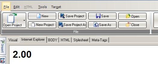
User Manual ii
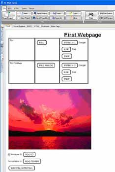
Table of Contents
1 Design, Connect, Realize with EZ Web Lynx ................................................1
1.1 Overview of Capabilities..................................................................................1
1.2 General Use....................................................................................................2
1.2.1 Industrial Environment .................................................................................2
1.2.2 Laboratory Equipment ................................................................................2
1.2.3 Consumer Products ....................................................................................2
1.2.4 Hobbyists ....................................................................................................2

2 Development Kit Hardware Setup & Software Installation...........................3
2.1 Contents of Kit.................................................................................................3
2.2 Software Installation........................................................................................4
2.3 Hardware Setup..............................................................................................4
2.4 Docking Station ..............................................................................................6
2.5 Example 1 Project and Hardware Check........................................................9
2.5.1 Exec/Read Keys...........................................................................................9
2.5.2 Conditionals................................................................................................10
2.5.3 Simulator.................................................................................................... 11
2.5.5 Controlling Web Content through Hardware...............................................12
2.5.4 HTML creation............................................................................................12
2.6 Using the EZ Web Lynx Development Kit ....................................................13
2.6.1 Manually Compiling and Loading Files to the EZ Web Lynx .....................14
2.6.2 Creating a Downloadable Image (Compiling) ............................................14
2.6.3 Downloading the Binary Image .................................................................14
2.6.4 Other Notes Regarding CSFS and Web Pages ........................................16

3 IDE Overview..................................................................................................17
3.1 Editor Features..............................................................................................17
3.1.1 File Formats...............................................................................................17
3.1.2 Using the Edito...........................................................................................18
3.1.3 File Tab.......................................................................................................19
3.1.4 Edit Tab.......................................................................................................20
3.1.5 HTML Tab...................................................................................................21
3.1.6 Tools Tab....................................................................................................22
3.1.7 Target.........................................................................................................23
3.1.8 Slide-out Windows.....................................................................................24
3.1.9 Using Command-line Parameters.............................................................24
3.1.10 Help File..................................................................................................25
3.2 Custom Web Pages......................................................................................25
3.2.1 HTML Instruction Set..................................................................................26
3.2.2 Example web page for reading temperature sensor..................................28
3.2.3 Example web page using conditional HTML tags.......................................32
3.2.4 Example 2: Using the Visual Editor............................................................36
3.3 Pin Input........................................................................................................37

                                                          iii                               EZ Web Lynx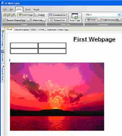
4 Using EZ Web Lynx........................................................................................38
4.1 Command Interfaces.....................................................................................38
4.1.1 Serial AT Command Interface.....................................................................38
4.1.2 UDP Server Interface.................................................................................39
4.1.3 HTTP (Web) CGI Interface ........................................................................40
4.2 Connections..................................................................................................41
4.3 Digital Input/Output........................................................................................43
4.4 Analog Input/Output.......................................................................................44
4.5 Counter Input.................................................................................................44
4.6 I2C Temperature Sensor...............................................................................44
4.7 Serial Communication...................................................................................44
4.8 Command Set...............................................................................................44
4.9 Features........................................................................................................57
4.9.1 Device Look................................................................................................57
4.9.2 Pin Lock......................................................................................................57
4.9.3 I2C Temperature Sensor.............................................................................57
4.9.4 Data Registers...........................................................................................58
4.9.5 Serial Capture Buffer.................................................................................58
4.9.6 Email.........................................................................................................60
4.9.7 LCD............................................................................................................61
4.9.8 Device ID....................................................................................................62
4.9.9 IP Discovery Announcements.....................................................................62
4.9.10 String Storage..........................................................................................63
4.9.11 Triggering..................................................................................................63
4.9.11.1 Triggering Inspect Algorithm..................................................................64
4.9.11.2 Triggering Action Algorithm....................................................................65
4.9.12 Authenticated Web Pages........................................................................65
4.9.13 TCPIP  SERIAL (T2S).........................................................................66
4.9.14 Network Connected Indicator..................................................................68
4.10 IP Configuration...........................................................................................68
4.11 WIFI Configuration and Troubleshooting.....................................................70
4.11.1 Connecting to a specific AP in Infastructure Mode..................................70
4.11.2 Connecting to best public AP in Infastructure Mode.................................70
4.11.3 Connect in AdHoc mode...........................................................................70
4.11.4 WIFI Networks and IP Networking............................................................71
4.11.5 Troubleshooting Connection.....................................................................71
4.11.6 Ad Hoc Input Pin......................................................................................72
4.11.7 LINK Disconnect Reason..........................................................................73

5 Additional Information..................................................................................74
5.1 General Specifications..................................................................................74
5.2 Electrical Specifications.................................................................................75
5.3 Host Inter-connects.......................................................................................75
5.4 Application Ideas...........................................................................................77
5.4.1 Industrial Refrigeration...............................................................................77
5.5 Test Equipment..............................................................................................78

6 Technical Support & Warranty Information.................................................79
6.1 High Volume Sales.......................................................................................79
NOTES................................................................................................................80
NOTES................................................................................................................81

User Manual                                               iv
EZ Web Lynx
  1 Design, Connect, Realize with EZ Web
                                     Lynx
EZ Web Lynx is a simple embedded network integration device to get your
products online fast!

This tiny unit can easily be added to any existing electronic design to gain TCP/
IP networking, reducing development and engineering time. Its dynamic web
pages are easily programmed in HTML with no other technical knowledge or
programming languages needed!

To fit your design requirements, there are 3.3V and 5V Ethernet versions and a
3.3V Wifi version. Start out with one of our development kits to see how EZ Web
Lynx can work for you. See Section 2 of this manual on the Development Kits for
more details.

1.1 Overview of Capabilities
    xx Three types of Command Interfaces -
         Serial AT Command Interface - Allows the user to configure and operate
         the device without the need for a network connection.
    xx UDP Server Interface - Included with EZ Web Lynx to accept AT
        commands and works with the EZ Web Lynx IDE to configure the
        device.
    xx HTTP CGI Interface - Commands can be issued to the EZ Web Lynx using
        HTTP CGI GET and POST commands.
    xx Analog Outputs – Some pins can be used as analog outputs (PWM with
         variable duty cycle).
    xx TCPSerial (T2S). Device can be put into a mode where it connects
         to a host via TCP, and all incoming TCP packets are sent out the serial
         port and incoming serial data is sent to the host (via TCP).
    xx Triggering/Alarms. Device can be configured to send e-mails or UDP
         packets upon certain pre-configured or timed events.
    xx Analog Inputs - Pins 1 - 5 on the 5V EZ Web Lynx or pins 1 - 6 on the
         3.3V EZ Web Lynx can be used as analog inputs. These inputs have the
         range GND-Vdd and a resolution of 0.01V
    xx I2C Temperature Sensor - 2 pins can be used to communicate with Dallas
         sensors to monitor temperatures in Fahrenheit or Celsius.
    xx Device Lock - Password protects EZ Web Lynx from changing the
         configuration of the device.
    xx Pin Lock - Allows I/O pins to be individually locked in their current state to
         prevent mode configurations from being modified.
                                         1                        EZ Web Lynx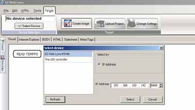
xx Data Registers - Volatile and non-volatile registers are available and
         consist of 256 8-bit register locations.
    xx Serial Capture Buffer - Allows the device to automatically capture a
         specific frame of serial data based on user-specified start and stop
         conditions.
    xx E-mail - EZ Web Lynx has the ability to send event-driven and/or daily
         status e-mails.
    xx Character LCD - Information read by EZ Web Lynx can be displayed on a
         character LCD.
    xx Device ID - Allows identification of a particular device in an environment
         with multiple EZ Web Lynx devices.
    xx IP Configuration - EZ Web Lynx allows for full modification of its
         networking settings, allowing it to be used in all network environments.

1.2 General Use
EZ Web Lynx was designed to offer a quick and easy way to get an existing
or a new product online. Its versatility allows quick adaptation into limitless
applications and be monitored from remote locations. The following are some
general examples of how EZ Web Lynx could be used:

1.2.1 Industrial Environment
Incorporate EZ Web Lynx into any industrial device to allow for local or remote
monitoring of equipment status. You can observe what functions are on, which
are off, if your machine is on schedule, or has the correct settings.

1.2.2 Laboratory Equipment
Adding EZ Web Lynx to your lab equipment allows you to audit the results from
various devices faster and monitor many at the same time. In addition, EZ Web
Lynx can notify you via e-mail when a test is done.

1.2.3 Consumer Products
EZ Web Lynx will give you a competitive edge with your products by providing
an innovative way to communicate over the Internet. This could be useful in
appliances like an oven or refrigerator. This would allow you to start pre-heating
your oven from work, or make sure you did not forget to turn it off after leaving for
a trip. With EZ Web Lynx e-mail functions, you can receive a notification email if
you forgot to close the refrigerator door, or if the temperature is too warm in the
freezer. For detailed directions on how to set up a similar example, please see
Section 4.4 “Application Ideas: Industrial Refrigeration.”

1.2.4 Hobbyists
EZ Web Lynx is a cost-effective module that can be incorporated into even the

User Manual                              2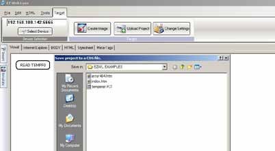
smallest projects. It is ideal for someone who wants to develop their own device
at home to monitor from any computer connected to the Internet. For example,
if you wanted to set up a home weather station, EZ Web Lynx can be embedded
into your weather monitoring system. You can view the results and current
conditions of your rooftop equipment from the comfort of your home workspace.

     2 Development Kit Hardware Setup &
                     Software Installation
                    * Network cable is not included in the WIFI Kit

                                                                           *

                       5V

2.1 Contents of Kit
The EZ Web Lynx Development Kit includes everything you need to get your
project started. Included in the development kit is:

    xx Two EZ Web Lynx devices
    xx Docking Station for programming and testing
    xx Host Ribbon Cable
    xx Network cable
    xx 9V Power Supply
         ◊ Serial to PC Cable
    xx CD-ROM
WIFI Kit also includes:

    xx RF Antenna Cable
    xx Antenna

                                          3                           EZ Web Lynx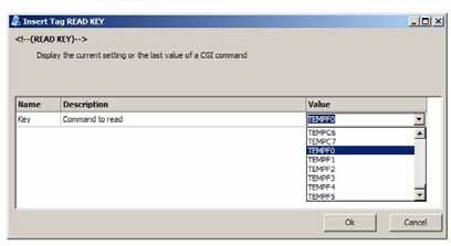
2.2 Software Installation
1. Insert the EZ Web Lynx CD in the CD-ROM drive.
2. Run D:\setup_ezweblynx.exe where D: is your CD-ROM drive.
3. Follow the on-screen instructions to install the EZ Web Lynx
           software to your computer.

2.3 Hardware Setup
Plug the EZ Web Lynx module into the connector on the docking station. If you
are using an Ethernet module, the Ethernet jack on the EZ Web Lynx should be
facing toward the bottom edge of the docking station. If you are using a WIFI
module, the antenna connector (U.FL) should be facing toward the bottom edge
of the docking station.

4. Plug the 9V power supply into the power connector on the bottom-left corner of
     the docking station. This will supply power to the docking station as well as
     the EZ Web Lynx module.
5. Set the EZ Web Lynx IP address settings to match your network. This can
     be accomplished in two ways. The first is to use the serial interface on a
     PC to change the settings. The second method involves a direct network
     connection between the EZ Web Lynx and a PC. If you are using a WIFI
     module, you cannot use the direct network connection if your Wireless
     Access Point (AP) requires authorization (WEP, WPA, etc).

  a. To change the EZ Web Lynx IP settings using the serial interface:
    1. Connect the supplied CPC—DB9 serial cable to the RS-232 port on the
         right side of the docking station and to the DB9 serial port on the PC.
    2. The red and white DIP switches are used to isolate the RS-232 port
         from the EZ Web Lynx. To enable use of the serial port, switch both
         DIP switches next to the RS-232 port into the CLOSED position. The
         switches should be flipped toward the LEDs.
    3. Pin 8 on the EZ Web Lynx is shared with the serial port. So the analog and
         digital inputs on the docking station do not interfere with the serial port,
         make sure BOTH of the number 8 switches on the blue and white banks
         in the top-left corner of the docking station are in the OFF position. They
         should be pointed toward the knob/buttons.
    4. Open a terminal program on the PC (Hyperterminal, etc.). The default port
        settings are 9600 baud/8 data bits/no parity/1 stop bit/no flow control (8-
        N-1). Change the terminal program’s settings to match this. Character
        echo is, by default, enabled on the EZ Web Lynx. Turn off the terminal
        program’s local echo option.
    5. Type “AT” (no quotes) and hit the enter key. The EZ Web Lynx should
        respond with an “OK” and then prompt you for the next command.
        The “AT” command does not perform any function other than force a
        response from the device to ensure the device is alive. If the EZ Web

User Manual                              4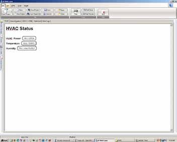
Lynx does not display the characters as you type them or does not
      respond to the command, re-check your cable connection, switches,
      and terminal settings from steps 1-6.
  6. Use the appropriate AT commands to change the network settings to
       match those from your network. Refer to the manual’s chapter on the
       “Command Set” for details on all of the legal AT commands. The AT
       commands follow the format “AT*KEY=VALUE” where KEY is “AIP”
       (change the IP address), “ANMASK” (netmask), “AGW” (gateway), or
       “ADNS” (DNS server) to change those respective settings. Value is
       the desired result. The IP address should be one that isn’t used by any
       other device on the network. The netmask, gateway, and DNS should
       be the same as the PC[s] on the network
  7. DHCP may also be used to dynamically assign an IP address to the
      device. To use DHCP, a DHCP server must be present on the network.
      Most networks do have a DHCP server; often a router will be acting as
      one. To enable DHCP, type “AT*DHCP=1” and press the enter key. The
      device should respond with an “OK” message.
  8. After changing the IP settings, the device must be reset before the
       changes will take effect. To do this, either type “AT*RESET=1” or
       simply press the RESET button on the docking station. When a new “>”
       prompt appears on the terminal screen, the device is ready to go.
  9. If using WIFI, the Wireless Access Point (AP) information has be set.
        Parameters that should be set are “WIFI_ASSID” (SSID of AP),
        “WIFI_SECURITY” (security mode of AP), “WIFI_KEY” (security key
        of AP), “WIFI_CHANNELS” (channels to scan for AP) and “WIFI_
        REGION” (your WIFI region). To join the best public AP available,
        set WIFI_ASSID to blank and WIFI_SECURITY to 0 (open). Refer
        to the manual’s chapter on the “Command Set” for details on these
        commands.
  10. Confirm the settings by typing “AT*KEY?” where KEY is the setting
      you would like to check. For example, to check the IP address,
      type “AT*IP?”. The EZ Web Lynx will respond with the following
      “AT*IP=RESPONSE” where RESPONSE is the IP address of the
      device.

b. To change the EZ Web Lynx IP settings by establishing a direct network
    connection with a PC:
  1. This method involves directly connecting the EZ Web Lynx to a PC and
       changing the settings of the PC to match the default settings of the EZ
       Web Lynx. This will allow the PC to communicate over the network
       connection to the EZ Web Lynx. The following instructions assume a
       PC running Windows XP. The procedure may differ slightly for other
       operating systems.
  2. If you are using a WIFI module, you can skip this step. Most computers
        will require a crossover cable in order to make a direct network
        connection. This cable IS NOT included with your EZ Web Lynx. Some

                                     5                       EZ Web Lynx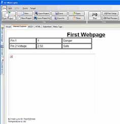
Network Interface Controllers (NIC) have a feature called automatic
        crossover which will allow the use of a standard network cable.
    3. If you are using an Ethernet module, plug the crossover cable into the
          Ethernet jack on the EZ Web Lynx and into the Ethernet jack on the
          computer. If you are using a WIFI module, plug an antenna into the
          antenna connector of the module and skip the rest of these steps.
    4. Open the Windows Control Panel and choose Network Settings. Right-
        click on the Local Area Network and choose Properties.
    5. In the Local Area Connection Properties window, click the Properties
          button.
    6. In the box that says “This connection uses the following items”, click on
          “Internet Protocol (TCP/IP)” and then click the Properties button.
    7. Select the “Use the following IP address” radio button and use the
         following settings:
    8. IP Address: 192.168.100.200
    9. Subnet mask: 255.255.255.0
    10. Default Gateway: 192.168.100.1
    11. Select the “Use the following DNS server addresses” and leave the
        fields blank.
    12. Click on the OK button on any open windows.
    13. The computer may pause for a moment while it resets its network
        connection. After a moment, the Local Area Network should indicate
        that it has connected.
    14. The computer will now have an IP address that will allow it to
        communicate directly with the EZ Web Lynx over the network
        connection.
6. With the network settings appropriately assigned, the EZ Web Lynx software
    will now be able to connect to the device to change settings, and download
    web pages. See the EZ Web Lynx IDE chapter in the user manual for details
    on using the software.

2.4 Docking Station
The docking station includes the following features for programming and testing
EZ Web Lynx operations:

    1. 14- pin connector to host the EZ Web Lynx module (See Section 4.3 for
         mates)
    2. Red/Green bi-color LEDs to indicate the high/low state of each pin
    3. User terminal block to allow access to each of the I/O pins on the EZ Web
         Lynx
    4. RS-232 level converter and serial connector for Personal Computer to EZ
        Web Lynx serial communications with a DIP switch to isolate RS-232
User Manual                             6
chip from device
5. Connector for 2x16 LCD module (LCD module not included)
6. Dallas DS1631 Temperature sensor with isolating DIP switch
7. In-Circuit Debugger/Programmer connector for advanced
programming
On the Docking Station, adjust the switch the following settings
1. Connect the temperature sensor to the EZ Web Lynx.
2. Connect EZ Web Lynx pin 1 to the analog input source.
3. Connect pins 2-4 to the digital input source.
4. All other pins should be left unconnected.
7 EZ Web LynxConnect Pins
to Analog Source to Host Board
Probe Points
5V
2 14 13 14
1 13
Anolog Voltage 2 14 LED
1 13 Connector
Source
1 2
Digital Voltage
Source (Odd Pins)
Digital Voltage
Source (Even Pins) LED PIN
Indicators
Temperature Sensor Isolator
Connect Pins
to Digital Source DS1631 Temperature Sensor 10, 11
Power 2 4 6 8 10 12 14
Source 1 3 5 7 9 11 13 RS232 8, 9
Selector Serial Port Isolator
ICD Connector
Power EZ Web Lynx
9V DC Pushbutton
RESET
Connect Pins
to Analog Source to Host Board
Probe Points
LCD Contrast 3.3V
2 14 13 14
1 13
2 14 LED
Anolog Voltage 1 13 Connector
Source
2
1
Digital Voltage
Source (Odd Pins)
Digital Voltage
Source (Even Pins)
LED PIN
Connect Pins Indicators
to Digital Source 2 4 6 8 10 12 14 16 18 20
1 3 5 7 9 11 13 15 17 19 Temperature Sensor Isolator
DS1631 Temperature Sensor 10, 11
RS232 8, 9
Serial Port Isolator
ICD Connector
Power EZ Web Lynx
9V DC Pushbutton
RESET
User Manual 82.5 Example 1 Project and Hardware Check
The following steps will create a simple webpage. The project will be downloaded
to the board and viewed in a web browser to check your hardware setup.
1. Open the EZ Web Lynx IDE by double clicking on ezweblynx.exe
2. Click on the New Project button under the File ribbon. Select a project
directory and name the project. Click save to create the project.
3. The IDE will create two default HTML files for use with the project: 1) index.
htm is the default HTML file for display in a web browser. 2) error404.htm
is the web page that is displayed when a browser is unable to display the
project. By default index.htm is opened displaying a simple hello web page.
4. Highlight and delete the sample text. Type your own custom text such as
“Hello World”
5. Save project from the File ribbon to save all changes to any files that have
been included in the project.
6. File ribbon also provides additional features such as: creation of new html files
to be included, opening of included html files, and printing. Download project
to target board by selecting in the Target ribbon “Select Device”.
7. A window will pop up displaying all EZ Web Lynx devices found on the
network. See section 4.1 to set up your network to allow for proper
functioning of the EZ Web Lynx.
8. Click Create Image and save the cds file to the project directory.
9. Click “change settings” to verify the IP address and ID of your development
kit. Write down this IP address so you can access the web page through a
browser.
10. Click “upload project”.
11. Open up a web browser on your computer and go to the address http://
YourIP and replace YourIP with the IP address that was written down in step
7.
12. The website that was created using the IDE should now be displayed
showing “Hello World”.
Congratulations, your network is now set up for use with your new EZ Web Lynx
module. The following chapters will explore more advanced features of the IDE.
2.5.1 Exec/Read Keys
In addition to simple PIN I/O the EZ Web Lynx has capabilities for writing and
reading various pre-programmed commands. These commands include sending
serial data, displaying to an LCD, setting up event driven emails, reading the
included temperature sensor, and various other functions. The below steps
implement such commands to the sample project.
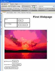
1. Move the cursor to a new line after the image and type “EZ Web Lynx ID:“.
9 EZ Web Lynx2. Select the HTML Ribbon and open the command drop down box. Select
“READ KEY” and click insert. Either type “ID” or use the drop down box
to select ID. Click Ok.
3. Move the cursor to a new line
and type “Temperature is: “
4. Make sure “READ KEY” is still
selected and click insert.
This time we want to read
the command “TEMPF0”.
After selecting the value click
Ok.
5. Open the command drop
down box and select “EXEC
KEY” and click insert. Type
“PIN_OUTPUT3” in the key
field and type 1 in the value
field. This will drive PIN 3 of
the EZ Web Lynx module to
high.
6. The window should look similar
to the following:
2.5.2 Conditionals
1. The EZ Web Lynx command set also includes the conditional statements
if and else. These conditionals can be used in conjunction with PIN
voltage levels or command values to generate different HTML. The if
command will only include the surrounding HTML when the conditional
resolves to true. So if the statement is false, then the module will not
include the surrounded HTML on the webpage. These can be very
useful to programmers allowing for custom embedded device driven
web content.
2. Execute the EZ Web Lynx IDE by navigating to the previously chosen
install directory and double click on ezweblynx.exe
3. Now the PIN 2 ANALOG command probably disappeared, so to make it
reappear simply click on the right line of the column and drag the mouse
to the right. This will expand the second column so the command can be
seen again.
4. Place your cursor in the top row of the newly created column and open the
command drop down box under the HTML Ribbon. Select “IF PIN X=N”.
Click insert. Type 1 in the “X” value field and high in the “a” value field.
5. Move the cursor to the right of this command and type “Danger”.
6. Open the command drop down box and select “ELSE”. Now type Safe
after the else command.
User Manual 107. Open the command drop down box and select “ENDIF”.
8. Place your cursor in the bottom row of the newly created column and open
the command drop down box. Select “IF PIN X[]N”. Click insert. Type
2 in the “X” value field. Select the greater than operator in the “OPT”
value field. Type 3 in the “a” value field. This command will evaluate to
true if the analog voltage on
pin 2 is greater than 3V.
9. Move the cursor to the right
of this command and type
“Danger”.
10. Open the command drop
down box and select “ELSE”.
Now type Safe after the else
command.
11. Open the command drop
down box and select
“ENDIF”.
Your window should now look like:
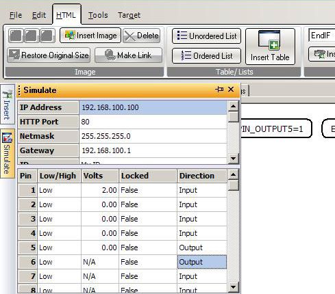
2.5.3 Simulator
The advantage of the IDE over other
HTML editors is the ability to simulate
the functioning of the website before
downloading to the module. Using the
simulate sliding window values can
be assigned to various commands
and pins so that commands can be
properly simulated. Follow these steps to set up and use the included simulator.
13. Move the mouse over to the left side of the IDE and hover over the
Simulate tab. This slide out tab allows for values to be assigned to pins and
commands so that included HTML commands can be simulated.
To simulate the current project start by typing “Test EZWeb” in the “ID” field
contained in the top subsection.
14. Next set PIN 1 to HIGH, and PIN 2 to 2.5V in the middle subsection.
15. Now select a blank text field under the Key subsection and type “TEMPF0.
Set the value to 80.
16. Move the mouse away from the simulate tab to cause it to slide back.
17. Click on the Internet Explorer tab to view the results of our simulation. This
window will display the currently opened webpage like it would be displayed
in a browser.
18. After opening the Internet Explorer tab, the IDE should look similar to the
following (Note the Image will not be displayed in this simulation):
11 EZ Web Lynx2.5.4 HTML creation
The IDE also includes a standard
HTML editor that can be used to
generate web pages without the
need for the visual editor. To use this,
select the HTML tab. All changes
that are made in this editor will also
be reflected in the visual tab and the
Internet Explorer tab. Additionally the
Body tab can be used to add HTML
into the body section of the webpage.
The IDE includes support for CSS
style sheets and meta tags. To
access these, use the corresponding
tabs. Every project created using
the EZ Web Lynx IDE will include a
default CSS sheet.
2.5.5 Controlling Web Content through Hardware
This section will describe how to use the EZ Web Lynx board to control the
project created throughout this exercise book.
1. Follow the steps from Section 2.5 to download the finished project to the EZ
Web Lynx board.
2. Open up a web browser and navigate to the module’s IP address.
3. The EZ Web Lynx development module includes a potentiometer, push button,
and temperature sensor that will provide the necessary data to the module.
This data will then be displayed in your web browser effectively enabling
your embedded board to be viewed through a web application.
4. First, before we can use the development module’s input devices, we need to
set up the board. The included development board has two DIP switch banks
of 8 switches per bank. These switches connect pins on the EZ Web Lynx
modules to the input devices.
5. To put the potentiometers input on pin 2, flip the DIP switch labeled number 2,
in the bank directly next to the Potentiometer, to the ON position.
6. We also need to attach the input of one of the digital buttons to pin 1. To do
this flip the DIP switch labeled number 1, in the bank next to the two digital
buttons, to the ON position.
7. Move the potentiometer and refresh the webpage. Notice how the “PIN 2
ANALOG” command changes value corresponding to your input voltage.
Additionally the danger text should change displaying the state of the device.
8. Use the push button to change the state of PIN 1 and refresh the webpage.
Notice the change in the “PIN 1” command as well as the danger text.
9. The actual temperature read by the on board sensor should also be displayed
at the bottom of the page.
User Manual 122.6 Using the EZ Web Lynx Development Kit
The blue bank of switches next to the knob isolates or connects the
potentiometer to the numbered pin on the EZ Web Lynx device. This allows the
EZ Web Lynx to be connected to a variable analog voltage source. When a
switch is in the ON position, that number pin on the EZ Web Lynx is connected to
the analog source. If it is not in the ON position, then the pin is not connected to
the analog source. 1
The push buttons provide a digital input to the EZ Web Lynx’s input pins. The
blue bank of switches next to the buttons connect or isolate the buttons from the
EZ Web Lynx. When a switch is in the ON position, that number pin on the EZ
Web Lynx is connected to the digital source. The pin will be normally low and
will be pulled high when the button is pushed. The top button, labeled “EVEN,”
controls even-numbered pins 2, 4, 6, and 8. The bottom button, labeled “ODD,”
controls odd-numbered pins 1, 3, 5, and 7. If a switch is not in the ON position,
then the pin is not connected to the digital source. 2
The “To Host” socket is for connecting the EZ Web Lynx pad to another device
using the supplied ribbon cable. The EZ Web Lynx pad does not supply power to
the +5V/+3.3V pin on the Host Connector.
The 3-pin header just below the bottom blue bank of switches chooses from
where the Docking Station and EZ Web Lynx will be powered. If the shunt is in
the “Adaptor” position, power will be supplied through the wall adapter. If the
shunt is in the “Host” position, a 5V/3.3V power source should be connected
through the “To Host” socket to power the Docking Station and EZ Web Lynx.
The two sets of red switches on the right side of the Docking Station are used
to isolate the temperature sensor and serial port from the EZ Web Lynx. The
switches on the top relate to the temperature sensor and the those on the bottom
to the serial port. If using pins 8 or 9 as digital I/O, put the bottom switches in the
OPEN position. If using the serial port, do not put them in the OPEN position.3
If using pins 10 or 11 as digital I/O, put the top switches in the OPEN position. If
using the temperature sensor, do not put them in the OPEN position. 4
1
Only pins 1-5 on the EZ Web Lynx 5V and 1-6 on the EZ Web Lynx 3.3V are capable of
acting as analog inputs.
2
Pin 8 is also used for serial communication, so make sure both number 8 switches are
not in the “ON” position if using the serial functions of the device.
3
The serial port on the Docking Station is connected through an RS-232 level converter
chip. This converts the TTL levels used on the EZ Web Lynx to RS-232 levels used by
computers. When using the serial port to connect the EZ Web Lynx to another device,
check that device’s specifications to see whether it uses TTL or RS-232 levels for serial
communication.
4
The Dallas DS1631 temperature sensor uses the I2C serial communication protocol and
requires pull-up resistors on the data and clock lines. The Docking station includes
4.7k resistors on both lines. When using the EZ Web Lynx on custom hardware, these
resistors must be included. See the “Temperature Sensor” section for more information.
13 EZ Web LynxThe 2x7 female header in the top-right corner of the board is used for connecting
an LCD to the EZ Web Lynx. See the “LCD” section for more information.
The black 6-pin modular jack on the bottom-right corner of the board is used for
connecting an in-circuit debugger/programmer (ICD) to reprogram your EZ Web
Lynx with custom firmware. This header provides access to the programming
pins needed to reprogram the processor on the EZ Web Lynx.5
2.6.1 Manually Compiling and Loading Files to the EZ Web
Lynx
Web pages and other files can be manually written, compiled, and loaded onto
the EZ Web Lynx without the use of the IDE. To do this a command-line utility,
named CSFS, as well as a file-transfer program are utilized.
2.6.2 Creating a Downloadable Image (Compiling)
The web pages that are to be stored on the EZ Web Lynx must be compiled to a
binary image that can be parsed and read by the device. This is accomplished
using the CSFS utility (csfs.exe) that is included in the directory to which the
IDE was installed. The program will compile all files from a given directory into
one file that is, in turn, downloaded to the EZ Web Lynx. All files that are to be
compiled and downloaded must be in one folder. This folder should not contain
any files that are not to be downloaded, nor should it contain any sub-directories.
CSFS is best used from a command prompt. The usage is as follows:
csfs INPUT_DIR OUTPUT_FILE
Where INPUT_DIR is the directory that contains all of the files to be compiled
and OUTPUT_FILE is the name of the file that is to be created. The output file
may be given any name. The program will display a list of the files that were
compiled before completing and returning control back to the command prompt.
2.6.3 Downloading the Binary Image
Once a binary file has been created using the CSFS utility, it must be
downloaded to the EZ Web Lynx using the Trivial File Transfer Protocol [TFTP].
There are many TFTP client programs available, including a command-line
program included in most versions of Windows. From a Windows command
prompt, the usage for the TFTP program is as follows:
tftp -i IP_ADDRESS put LOCAL_FILE image.cds
5
Reprogramming your EZ Web Lynx using an ICD is for advanced users only. Damage
caused by reprogramming the EZ Web Lynx or the cost of reprogramming the device to
factory specifications is not covered by your warranty. Contact EZ Web Lynx technical
support for more information.
User Manual 14Where IP_ADDRESS is the IP address of the EZ Web Lynx device and LOCAL_
FILE is the name of the binary file created with the CSFS utility. The remote
file name (the last parameter) must be “image.cds” or the EZ Web Lynx will not
accept the file transfer.
Other TFTP client programs are widely available and may be used to complete
this transfer. If using a different program, ensure that the following settings are in
place:
xx Octet mode (also known as image mode or binary mode) will ensure that
the TFTP software transmits the CSFS image exactly as it was created
xx Block size must be 512 bytes (characters)
These are standard TFTP specifications, but some programs may override these
parameters by default. Once the file transfer is complete, the uploaded files are
viewable from a web browser.
TFTP does come with Windows Vista and Windows 7, but is disabled by default. To
enable TFTP in Windows Vista and Windows 7, follow these steps:
1. Open Control Panel
2. In the search panel of the Control Panel, enter ‘features’ to search.
3. When search is complete, you should see a choice labeled ‘Turn Windows
Features nn or off’ – click on this.
4. A new dialog box showing all the enabled and disabled features.
5. Enabled features have their checkbox checked. Scroll down until you see
‘TFTP Client’. Check this box, then press the ‘OK’ button.
15 EZ Web Lynx2.6.4 Other Notes Regarding CSFS and Web Pages
Some points to keep in mind when creating web pages and images to use on the
EZ Web Lynx:
xx The EZ Web Lynx will look for a file named “index.htm” when accessing
the device from a web browser and a file name is not specified. For
example, when you type “http://192.168.100.210/” in the address bar of
the web browser to access your device, the EZ Web Lynx will try to load
a page named “index.htm.” You should include a file with this name as
the default page you would like to have displayed.
xx When a requested page cannot be found in the device’s memory, a very
basic 404 error (file not found) web page will be displayed. You can
include a file named error404.htm in the downloaded image if you would
like a custom 404 page to be displayed instead.
xx Internet Explorer will automatically replace any error pages that are less
than a specified size with its own default error page.
xx The device must parse all characters in a web page when looking for
custom HTML tags. Keep unnecessary spaces, tabs, newlines, and
comments to a minimum to improve loading times.
xx CSS may be included directly in the section of web pages or
may be linked to by inserting a tag in the section. By
doing this, one file can be used for multiple web pages—saving on the
amount of memory used on the device. The EZ Web Lynx will also
tell the browser to cache all files with a .css extension so it only has to
be loaded from the device one time. Because of this, if a CSS file is
changed, the page must be fully reloaded (CTRL+F5 in most browsers)
to see the changes take effect.
xx To decrease loading times, the EZ Web Lynx directs the browser to cache
all images. Large images, JPEG files, and BMP files are particularly
taxing on the device and can take a long time to load. If possible,
relatively low-resolution GIF images are recommended because of their
relatively small file size and, therefore, quicker loading times.
User Manual 163 IDE Overview
The EZ Web Lynx IDE is an integrated development environment (IDE) designed
to assist developers in creating a web application using an EZ Web Lynx
device. The IDE provides a visual interface for creating a HTML document and
also allows for editing the document as raw HTML. The IDE can be used for
configuration
of an EZ Web
Lynx device
settings and
to upload an
HTML image to
the device.
3.1 Editor Features
The EZ Web Lynx IDE has five ribbon menus with useful features in each one to
make development quick and easy. The following are a few specific features that
require additional information:
3.1.1 File Formats
When working with the IDE several files may be created or used. The following
are some of the files that may be encountered. All files must be in 8.3 format.
xx CDS - A CCS Data Stream file. This contains an image of the web
application that may be uploaded to a device. These files are created by
opening a project and selecting “Create Image” from the target menu.
xx PJT - A project file. The project file contains a list of the files that are
included when creating an image that will be uploaded to the device.
xx HTM - A web page document. An HTML document is a plain text file with
special tags indicating the formatting. An HTML document may consist
of text, images, tables and hyperlinks to other sites. HTML is a standard
format for web pages and is known for its ability to allow users to view
information and follow hyperlinks to other locations of interest. For more
17 EZ Web Lynxinformation on HTML documents visit www.w3.org
xx JPG or .GIF or .PNG - An Image file. Image files may be included in the
project so that HTML documents may reference them. A web browser
may then display an image on a web page.
xx CSS - A file containing a Cascading Style Sheet. These files contain
information about how an HTML document should be presented by the
web browser.
3.1.2 Using the Edito
The IDE provides an HTML editor with several ways of viewing an open
document. Select from one of tabs at the top of the editor window for the various
ways to view and work on the document. Developers may find it useful to switch
between modes. The following modes are available:
xx Visual - Working in visual mode allows for quick editing of the
document with minimal knowledge of HTML and provides real-time
editing. Specific options such as changing fonts, inserting custom tags,
and inserting tables are only available in this mode. Other views require
tags to be manually typed in.
xx Internet Explorer - At some point a developer will want to know what the
document will look like in a web browser. This may be
different than in the visual view because of dynamic content. The
‘Internet Explorer’ mode gives the developer a powerful tool to
simulate what the document will look like when the EZ Web Lynx
processes the dynamic content. A developer can also change values in
the simulate slide out menu to view how the device responds in different
settings. The editor is ‘read only’ in this mode.
xx Body - In an HTML document, the body section defines the content of the
document. If the developer finds it easier to edit the HTML directly then
this mode will allow editing HTML content without having to work with
items such as the style sheet or tags that may be found in the HEAD
section.
xx HTML - This mode shows the full raw HTML document in plain text. This
allows the developer the greatest flexibility when editing an HTML
document.
xx Style sheet - This view gives the developer an ability to edit or add to the
style sheet for the document. A Cascading Style Sheet describes the
presentation of a document. The style sheet displayed here is found in
the head section of the HTML document.
xx Meta-Tags - Allows for viewing the Meta-Tags for the open
document. This view is read only. Meta-Tags provide information
about the document such as keyword, content, description and author.
For example,
instructs the web browser that the page is about EZ Web Lynx. This
is often utilized to enable search engines and web crawlers to rank the
page. Any number of Meta-Tags can be placed in the header section.
User Manual 183.1.3 File Tab
Developing a web application consists of creating one or more HTML files. Also
in order to place your application on the EZ Web Lynx device each file must be
part of the project. This ribbon allows for creating new projects and adding HTML
files. Support for printing is also provided.
Open Project Opens a saved project into the IDE
New Project Creates a new project
Save Project Saves the project settings
Save Project As Prompts the user for a project name to save the curently open project
New Creates a new blank HTML file an adds it to the current project
Save Saves the HTML file that is open (use 8.3 format for file name)
Save As Prompts for the file name to save the file currently open
Open Opens an HTML file to edit
Close Closes the project
Print Prints the file displayed in the print tab
Printer Setup Select the printer and printer options
Print Preview Preview the printer document
Exit Exit the software
19 EZ Web Lynx3.1.4 Edit Tab
To provide the developer with an easy way to edit documents, an option- rich
editor has been included. Depending on editing mode and where the cursor is,
some options may not be available.
Undo Undo the last edit to the program
Redo Redo the last undo
Cut Move the selected text to the clipboard
Copy Copy the selected text to the clipboard
Paste Move text from the clipboard to the editor
Import Text with line breaks Load text from a file into the editor keeping the line breaks
Import Text without line Load text from a file without the line breaks
breaks
Decrease list indent Un-indents a list item by one level
Increase list indent Increases the indent of a list item by one level
Remove Removes the innermost span. To set formating options
innermost span HTML documents use a span tag for example text
This option removes the innermost span at the cursor location.
Edit table Allows the insertion/deletion of the selected table rows or columns
Font settings tool bar The font settings tool bar allows the user to change the font style
for the selected text
User Manual 203.1.5 HTML Tab
Working with HTML documents consists of adding tags to control how images are
inserted, text is formated, and text hyperlinks are formed. If the editor is in visual
mode, this tab is available to help the developer format the document.
Images
Insert Picture Brings up the insert picture dialog giving the following options
Pictures Source The location of the image to insert. A copy of the image will be placed in the
project directory if the image location is not in the project directory (use 8.3
format for file name)
Alternate Text This is the text to display if the web browser can not display images
Layout Align an image left, right, or center
Size Select the height and width of an image. If the Aspect ratio box is checked then
the image will scale proportionally as the height or width are changed
Make Link Makes the selected image into a hyperlink. If the image is a hyperlink, the
user can click on it and be taken to a location providing more information. For
example a company logo could be made to link to the company web site
Delete Link Remove the hyperlink attribute from the selected image
Restore If an image has been resized, the developer can use the
Originial Size option to return the image back to its default original size
Align left, This allows an image to be aligned on the left, in the center, or on the right side
center, right of the page
Table/Lists
HTML items such as tables, lists and cell option commands can be inserted into
the document.
Unordered List Inserts an unordered list at the cursor position (ie. Bullet points)
Ordered List Inserts an ordered list at the cursor position (ie. 1,2,3...)
Insert Table Brings up the insert table dialog to insert a tab
Table Settings Select the number of columns, number of rows, the width in pixels, and the
table class and table style. Table class and table style are taken from the style
sheet.
Cell Options The user can change the cell spacing and cell padding in this dialog. The user
can also change the cell class and the cell style in this dialog. Cell class and
Cell styles can be defined in the style sheet.
21 EZ Web LynxCommands
To assist the developer in using dynamic content for the EZ Web Lynx Server,
some options have been provided.
Select an EZ Web Lynx command from the pull down menu in the tab and press
insert for the command to be placed at the current cursor position. A dialog
box appears and the user is allowed to enter any parameters for the command.
Please see the list of commands in the EZ Web Lynx documentation for a better
understanding of what the parameters are and how the commands effect the
display.
After inserting a command, the developer may click on a command and select
‘Edit device CMD’ to edit the parameters for a command in the HTML document.
A dialog box opens, allowing the user to change the
parameters for the command easily without having to worry about the syntax for
the command.
Hyperlink
Make Hyperlink Creates a hyperlink out of the selected text using the link in the ‘link edit’
box. The selected text may now be clicked on to take the user to a location
providing more information about the text.
Remove Hyperlink Removes the hyperlink at the current cursor locations
Anchor Adds an anchor at the current cursor position. An anchor creates a link within
current document
3.1.6 Tools Tab
The EZ Web Lynx IDE is a functional editor and some common editor functions
have been provided to assist the developer.
Document
Spell Check Spell checks the open HTML document
Word Count Displays the number of words in the HTML document
Spell Check Options Dislays settings for spell checking
Graphics List Shows a list of graphic files used by the HTML document
User Manual 22View
Show Tags Box checked - the tags are displayed in the HTML editor view
Insert Box checked - the insert slide out menu becomes visible
Project Manager Box checked - the project manager becomes visible. The Project
Manager allows all pages and images of the current project to be viewed.
Simulate Settings Box checked - the settings for how the document will be simulated
Simulate Errors Box checked - a list of errors that occurred the last time the project was
simulated will be visible. (See Section 3.9)
3.1.7 Target
The IDE allows for transferring a project to the device as well as viewing and
changing device settings.
xx Create Image: After loading a project, use this option to create an image
of the current project and save it to a disk. The image file format does
not support sub-directories. This means that any links to images or
files in the project must be to the same directory. Once the an image is
created, it may be uploaded it to one or more EZ Web Lynx devices.
xx Select Device: Press ‘Select Device’ to choose which device to
communicate with. The select device dialog box on the left will list all the
devices found on the local network. The refresh button refreshes this
list. If the IP address and port of the device is know, it can be entered
manually or be selected from the device list. Press select to choose the
device
xx Upload Image: After a device is selected, the project can be
uploaded to the device. Clicking upload image prompts the user for an
image file and uploads that file to the device selected.
xx Change Settings: The network settings for the EZ Web Lynx device
may need to be viewed or changed at times. The settings that can
be changed include IP Address, Gateway, DHCP, Netmask, ID, UDP
Port, HTTP Port, and TFTP Port. A device must be selected to use this
option.
If the IDE is behind a firewall and has problems communication with the device,
then the firewall settings may need to be changed. By default the IDE uses UDP
ports 7124 and 7123 to detect the device. The firewall may also need to be set to
allow for UDP, TFTP, and HTTP traffic to and from the device. Note that the ports
used can be set differently for each device. Contact your system administrator for
assistance.
23 EZ Web Lynx3.1.8 Slide-out Windows
Along the left side of the IDE window is a series of slide-
out windows for the user to quickly include files, insert
document tools or simulate the web view.
xx Project Manager: Contains a list of files in the
current project. Checking a file will include the
file in the project image that can be uploaded
to the device. The device does not support
sub-directories. It is recommended that all
files in the project be kept in the same
directory, as the file will always be placed in
the root directory on the device. To add an
add existing file to the project select add. To
remove a file from the current project highlight
the project in the list and select remove. All
files must be in short (8.3) format.
xx Insert Tab: This window allows for easy insertion
of images, lists, and other HTML objects as
well as EZ Web Lynx commands. Position the
cursor in the editor and click the command to
insert. This option is available only when the
editor is in the visual mode.
xx Simulate: A visualization of the dynamic content
output. Choose the Internet Explorer mode in
the editor. This mode will simulate any of the EZ Web Lynx commands.
Any of the network settings, ID, serial number, Pin status, and key
values may be entered or changed. Press the refresh button to update
the display using the current settings.
xx Simulate Errors: This window displays potential problems that were
detected the last time the IDE simulated dynamic content. Some
problems that are detected are, missing Endif tags and key values with
incorrect parameters.
3.1.9 Using Command-line Parameters
Some users may find it useful to create a project outside of the IDE or the user
may want to automate the process of uploading a project to a device. To support
this some functions of the IDE can be invoked from the command line as follows.
User Manual 24–P Project_file Image_file Creates an image from the project file and saves it as
Image_file
–D source_dir Image_file Creates an image using all files in source_dir and saves it as
Image_file. This allows an image to be created without the
project file created by the IDE.
–U IPAddress:port Image_file Uploads the Image file to the device at IP Addess:port. Note
that port is the UDP command port for the device.
3.1.10 Help File
The Help File included with the EZ Web Lynx IDE enables users to obtain details
for programming. The Help File has three topics: 1)IDE Function explainations
2) Basic HTML tags, and 3) Custom HTML tags.
3.2 Custom Web Pages
One of the features of the EZ Web Lynx is the ability to create and upload custom
web pages to the device. Using a set of custom HTML tags (see Section 4.14
HTML Instruction Set), the web pages interact with the EZ Web Lynx device to
view the conditions of the I/O ports, change the device settings, view incoming
data, and more. The EZ Web Lynx IDE has the ability to create, simulate,
compile, and upload web pages from a PC to any EZ Web Lynx device. (See
Section 4.9 for creating and uploading web pages to an EZ Web Lynx device.)
Some key information regarding the custom web pages:
xx The EZ Web Lynx has around 1MB (one megabyte) of flash memory
available for storing web pages.
xx There are two pages that the device may look for, and therefore, should
be part of the pages loaded onto the device:
- index.htm will be loaded when the IP address accessed by a web
browser and no file is specified in the URL
- error404.htm will be loaded when the requested file cannot be found.
If not provided, a simple 404 page will be generated.
xx File types supported:
- HTML (.htm extension)
- XML (.xml)
- Text (.txt)
- GIF (.gif)
- JPEG (.jpg)
- PNG (.png)
- Icons (.ico)
- Cascading Style Sheets (.css)
- All other file extensions will be read as plain text
xx Files should be in 8.3 character format
• Custom HTML tags will be processed in any type of file, as they are
read, except for within images of supported types.
25 EZ Web LynxYou can also read