Heidelberg Instruments Conversion software "x-convert" - Design in layout editor format - EPFL
←
→
Page content transcription
If your browser does not render page correctly, please read the page content below
Heidelberg Instruments
Conversion software "x-convert"
Design in layout editor
format
cut in stripes
Heidelberg internal format "lic"
Convert_V13_2020-03-27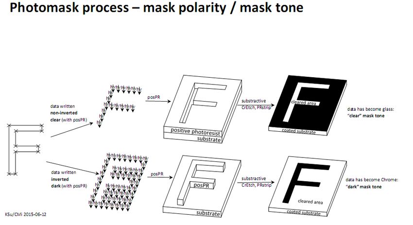
Manual of x-convert Conversion GUI

1.   Copy your layout data file
2.   Start Graphical interface
3.   Configure your exposure job

Figure 1: Mask Mirroring
Figure 2: Data polarity for mask and direct writing
Quick Overview Summary

This GUI is running on a Linux OS workstation free of access. Do not book VPG200 or
logon for use.
GUI help user to prepare a script for immediate computing bitmap information for use
as a real-time high rate flux for the VPG200 laser writer. Common layout are
computing in 1 to 10 min. Exceptional layout with ‘decoration’ periodic structures or
computed generated diffraction elements may take several hours.
More than one GUI interface can run under Linus OS operating as a multi-task system
Copy your design data
conversion-pc
Email data directory
Online storage: (linux-OS)
Safenet.epfl
user-pc, zone PC
Domain EPFL intranet
\\sti1files\cmi-transfert
• Do not use special characters such as
-.,;:?*()@!
• File extension in lowercase only
gds, cif, dxf
•
Do not make softlinks to design data residing outside of the gdsii/cif/etc.
directories.
(the software cannot handle it)
Do not create subdirectories within the gdsii/cif/etc. directories
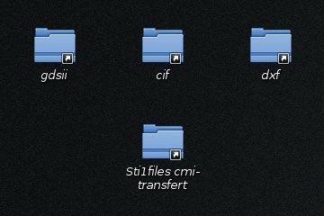
Link to the cmi-transfert server is found on the desktop.
Drag it to one of the folders “gdsii” / “cif “ / “dxf” that sit on the desktop.
move or copy here to start transferring data.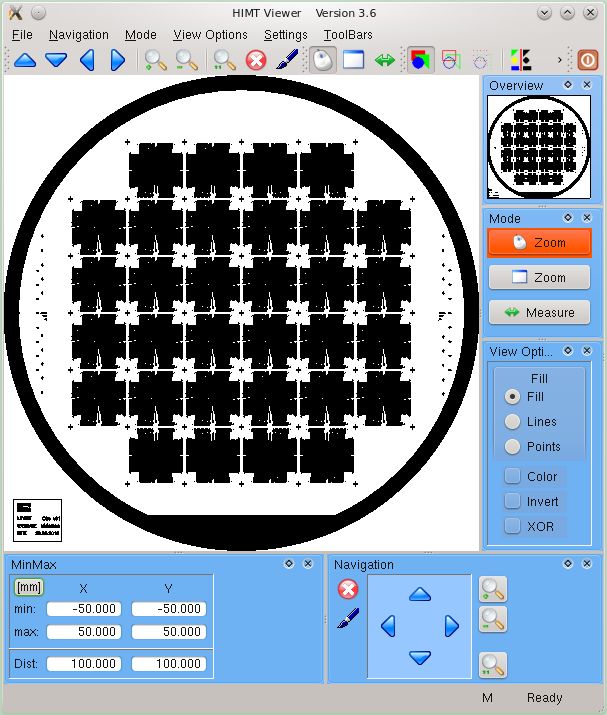
Start conversion software
Use left working station Activate with mouse (NO password required)

                    Start conversion application

                    or

                    Use a terminal window; type “app” on the command line

Conversion user interface pops up, click on white page or “File”

Start with a new job. Rename with your name
     "
e.g. John Doe -> jdo_crocodile_v2_lay28
     (max 28 characters)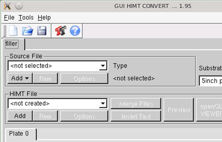
Step 1 – retrieve design

Conversion user interface is updated
with frame containing your job name.
    "

Continue specifying the design data:
Source File: Add
(Do not use add in HIMT section)

Opens a popup
“Load GDSII Design” or
“Load CIF Design” etc...

Dialog to retrieve your file in the
corresponding folder opens. Select and
confirm with “open”

Next window open with a specific data type
filter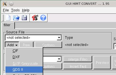
Step 2 – "gds" filter: Top cell & Layers
GDSII filter window opens:

 GDSII Structure: Select design's structure
(Main symbol, top cell or renamed top
view)
Unselect all
 (or view one)

Select Layer Nr 0: (tick box)
Point on your GDS layer number
Optional repeat for next Layer Nr.2 and
    select bitmap boolen operation
In example “Layer Nr.1” reads data from
    GDSII-file “50” and add ir to GDSII-file
    “0”

When done, click “Create Default”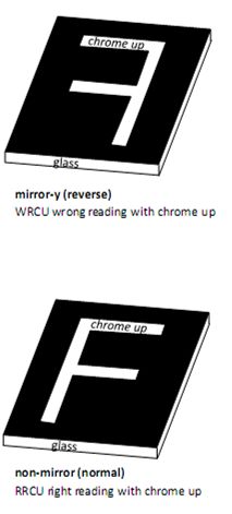
Step 2 – "cif" filter: Top cell & Single layer

CIF Options pop up window opens:

Top Cell: Select design's structure
(Try automatic to select “fabrication cell”)

Layer: Select correct layeramong listed of
   CIF-LayerNames found.

When done, click “Create Default”
Step 3 – View selected data
               Open a Viewer to review your selection:
               Old school: “Tk/Tcl Preview”
               New style preview is preferred (easier to find
               commands)

               Check for mask size and center

               Select “Fill” mode to view inside polygones in
               black (exposed area)

               Simulate inverted mode. If selected must be
               set “dark mode” at step 5
               Two zoom mode available:
               Mouse click (2x) or Window (define box area)
               “Measure” activate a tool for measurement

               Close preview and return to convert interface
               window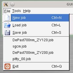
Step 4 – Write Head Selection
Select write lense:
Spot size / Resolution are hardware
dependent
3 lenses are available with
following specifications
Lenses are labeled by focal length
[mm]
write write Beam pixel stripe number write write time for
mode head / diameter* size width of stripes speed 110mm x 110mm
write [um] for width
lense [nm] [um] 100mm [mm2/min]
High Speed 20mm 0.8 1000 1000 100 1960 6’ 10”
Standard 10mm 0.9 500 500 200 980 12’ 30”
Advanced 4mm 0.65 200 200 500 190 65’
Advanced+ < 0.5 200 140 715 < 140 > 125’
* Minimum structure width in X/Y axis direction simultaneously. Vertical lines are smoother than horizontal.
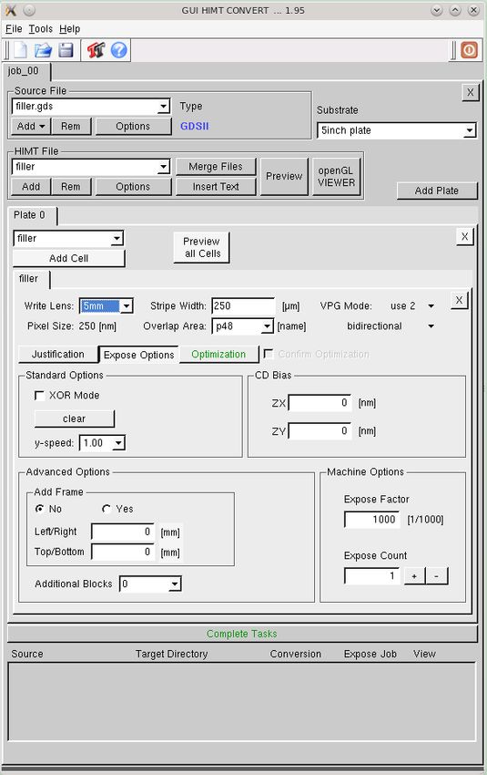
Advanced+ mode is available for 600nm critical dimensions subject to certain layout restrictionsStep 5 – Check Option: 1-Geometry
Select Justification tab
Expose Window
Must fit with your design.
When size is smaller as expected double
check for design's structure at step 2
Borders
Shows Upper/Lower/Right/Left limit of
exposure. In case of inverted design
oversize the limit to the full wafer or use
“add frame” in next options (step 6)
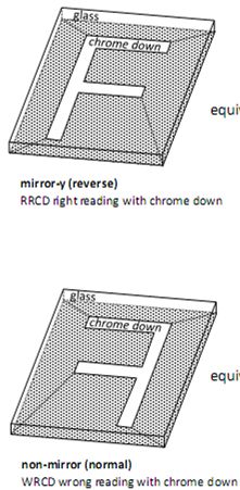
Mirror at Y
Activate mirroring for all top side masks.
Do not activate for backside masks or direct
writing Automatic Centering:
WARNING: Automatic centering may dis-align next
layer masks. Maybe use only for single layer project.
Check with Position Preview how looks your design
position relative to the Cr-plateStep 6 – Check Option: 2 - Exposure Polarity
Select Expose options tab:
Mask polarity
clear = non-inverted
insides of layout polygons are written
dark = inverted
outsides of layout polygons are written
CD Bias
Default beam symmetry correction is
loaded here
Add Frame
Active only with “dark”
Add a clear frame oversizing
exposure window. Borders in step 5 do the
same jobStep 7 – launch for computing Skip “optimization” Activate “Complete task” Design name can be changed before saving. Do not create sub-directory Conversion are for VPG200 (No need to logon or book the tool to perform conversion with the present manual. Linux operating system support multi task conversion. You can access the conversion PC at any time include overnight) Wait for completion of conversion. Conversion progress bar is activated. Acknowledge end of conversion with Will close this window ! Your conversion data are archived after 30 days !
Step 8 – Job Management: Cleanup and Refresh
Refresh your old conversion
Auto archiving or major tool parameter update may
purge only bitmap data. Source files and related
conversion parameters are always available for easy
refreshment with File

Select your job_name file (extension .job) on the
top directory to retrieve the status of ‘Step 7’ ready
to launch for computing.

Cleanup for confidentiality
If you need to remove your design and
conversion data from the conversion pc,
then follow these steps:
Tools->JobDirManager
Select delete job, expo, dir, and source
file.
Layout Mirroring

 typical for
 TSA mask

                               flip->

typical for
BSA mask and
direct write laser
                               flip->
Reverse pixel polarity (Data Dark) is valid only in exposure window leading to unexpected result
(second line below). Extension of exposure window or adding a frame fix the problem
non-inverted
clear
inverted
dark
dark
with frameQuick Overview Window when you begin: Click-path through progressively disclosed window:
You can also read