Quadrilateral-Shaped Wideband Circularly Polarized CPW-Fed Monopole Antenna - URSI
←
→
Page content transcription
If your browser does not render page correctly, please read the page content below
URSI AP-RASC 2019, New Delhi, India, 09 - 15 March 2019

         Quadrilateral-Shaped Wideband Circularly Polarized CPW-Fed Monopole Antenna
                                  Prashant Chaudhary (1), Ashwani Kumar (2) and Raj Mittra(3)

             (1)
                Department of Electronic Science, University of Delhi South Campus, New Delhi, India - 110021
                (2)
                    Department of Electronics, Aurobindo College, Delhi University, New Delhi, India – 110017
      (3)
          Department of Electrical and Computer Engineering, University of Central Florida, Orlando, Florida, USA and
                                       King Abdulaziz University, Jeddah, Saudi Arabia.

                     Email:prashantelec129@gmail.com, ashwanikumar7@yahoo.com, rajmittra@ieee.org

                        Abstract                                    with a relatively narrow bandwidth [1]– [2], which may
                                                                    not be suitable for many applications.
This paper presents a new type coplanar waveguide
(CPW)-fed       quadrilateral-shaped  compact     planar            A review of the literature reveals that considerable effort
monopole antenna with wideband circular polarization                has been invested by researchers in implementing various
(CP). The antenna operates in the C-band (5.96-8.0GHz),             techniques [3–8] toward realizing circularly polarized
as well as in the X-band (8.0-11.72GHz) and provides                (CP) antennas that are both wideband and compact. Some
circular polarization (CP) in both bands. The fractional            of the suggested techniques are: using L-slot antenna with
axial ratio (AR) bandwidth for CP 55.86% (5.96-                     single fed by L-shaped feed line [3]; combination of slot
10.58GHz) and fractional bandwidth of 118.2% (4.5-                  and printed monopole [4]; chifre-shape CP monopole
17.5GHz) for the return loss (S11) is realized simply by            antenna [5]; protruded in L-shape strip and inverted L-
designing a quadrilateral-shape monopole with an                    shape strip [6]; inverted L-strip and asymmetric ground
asymmetric ground plane. The proposed CPW monopole                  plane [7]; modified L-shaped patch with conjugation of
antenna structure is simple and compact, its design is              rectangular slot in the ground plane [8].
efficient, and it has a wide impedance matching (S11)
band as well as 3-dB axial ratio (AR) operating band.               CPW-fed antennas can be readily fabricated and
Simulated and experimental results are presented to                 packaged, making them a suitable choice for MMIC
validate the antenna design and are shown to be in good             application in wireless communication system. This paper
agreement.                                                          presents the design of a compact planar monopole
                                                                    quadrilateral-shape CPW feeding antenna with
1. Introduction                                                     asymmetric ground for wideband circular polarization
                                                                    (CP) with an axial ratio bandwidth of 55.86% and
In modern wireless communication system, the demand of              impedance matching (S11) bandwidth of 118.2%. The
circularly polarized (CP) planar antenna is witnessing a            proposed antenna is useful for C-band and X-band
rapid increase because CP antennas are polarization                 communication systems.
independent of the incident wave and, hence, they find
many applications in hand-held devices as well as in                2. Antenna Design
RFID and rotating systems. It is desirable to use antennas
with circular polarization (CP) to avoid the effects of             Fig.1 shows the layout and fabricated quadrilateral-shaped
path-loss and displacement of the antennas, when the                CPW-fed proposed planar antenna. The radiating surface
position of the transmitting and the receiving antennas are         has a quadrilateral shape and an asymmetric ground plane,
changing, or their operation is insecure to the weather             both of which are built on the same side of the FR-4
conditions. The basic principle of generating the circular          substrate, with an ε r = 4.4 and thickness of 0.8mm. A
polarization (CP) is to excite two orthogonal modes in a            step-impedance resonator is inserted in the central
phase-quadrature that have equal amplitudes [1]. A                  feedline to get better return loss (S11) of the proposed
variety of approaches to realizing CP antennas have been            antenna. The length and width of the lower line are 6mm
reported in the literature. These include, for instance, the        and 1.5mm, respectively, while they are c=2.07mm and
use of two orthogonal feeds, though this makes the                  d=3mm for the upper line. The gap between the feeding
antenna structure complex and bulky [1]-[2]. Circularly             line and the ground plane is 0.75mm. The shape of the
polarized (CP) antenna is also designed by using either a           radiator is a quadrilateral which is connected to the CPW
single feed at 450 along the axis of the patch or by corner         line. An asymmetrical ground has been added to generate
truncation of the square patch. However, the single-feed            the circular polarization. The detailed dimensions of the
techniques discussed in above references generate CP                proposed antenna structure (see Fig.1) are: Wx=30mm,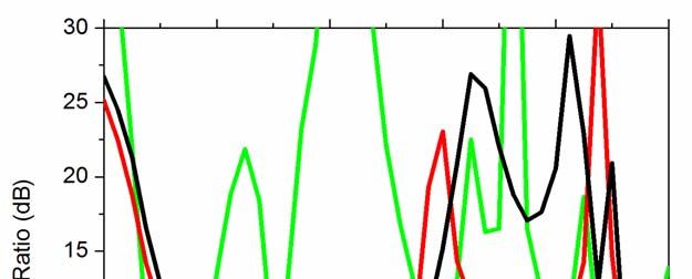
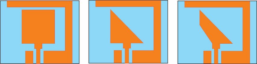
Ly=25mm, L=13.43, W=13, a=7.43, b=5mm, G1=3mm, designed by truncating the lower side of the antenna-2,
Gr=11.3mm, W1=2.8mm, l1=5mm, lx=23mm. which is in right angle triangular patch is truncated to
derive the antenna-3. The dimensions of antenna-3 are
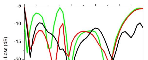
shown in Fig.1. Antenna-2 has an impedance matching
band that ranges from 4.5GHz to 15.6GHz while antenna-
3 has impedance matching band from 4.5GHz to 17.5GHz
as shown in Fig.3a.
Antenna-1 is linearly polarized antenna and antenaa-2 has
narrow band circular polarization band (8.5GHz to
9.2GHz) while antenna-3 has wideband circular
polarization bandwidth (5.96-10.58GHz) as shown in Fig
3b. The 3-dB axial ratio band improves when the antenna
design is progressively modified from step-1 (Antenna-1)
to Step-2 (Antenna-2), and then to step-3 (Antenna-3).
(a)Layout (b)Fabricated antenna The ratio of the amplitude of the electric far field
components (Ex/Ey) and their phase difference (PD) are
Figure 1. Proposed antenna structure shown in Fig.4. To realize the circular polarization (CP),
we need to work with two electric far field components
The primary objective of this paper is to design an (Ex and Ey) that have the same amplitudes
antenna with a circular polarization (CP) which has a
compact size and yet a wide bandwidth. Hence, the
geometry of the antenna is adjusted in such a fashion that
it generates two components of electric field (Ex and Ey),
with equal amplitudes and a 900 phase difference, to
generate the desired circular CP. Towards this end, a
quadrilateral-shaped patch with an asymmetric ground
plane has been used to achieve wideband circular
polarization.
Any circularly polarized (CP) antenna should have its 3-
dB axial ratio (AR) bandwidth entirely within the 10-dB (a)S11 of steps 1-3 (antennas 1-3)
impedance matching (S11) band. Hence, the primary issue
for the designing of circularly polarized antenna is
focused on how the quadrilateral-shape radiator and
asymmetric ground plane simultaneously improves the
10-dB return loss and 3dB axial ratio (AR) bandwidths of
the antenna. Therefore, the proposed antenna is designed
in three steps, as shown in Fig. 2 below, with the
progressive transformations designated from Step-1 (Ant-
1) to Step-2 (Ant-2) and to Step-3 (Ant-3).
(b) 3dB axial ratio bandwidth at steps 1-3 (antennas 1-
3)
Figure 3. Response of Step-1 (Ant-1), Step-2 (Ant-2)
and Step-3 (Ant-3)
(a) Step-1(Ant-1) (b) Step-2 (Ant-2) (c) Step-3(Ant-3)
Figure 2. Design steps of the proposed antenna
The proposed antenna structure is simulated by using
HFSS version-16. Step-1 which is Antenna-1 has only a
square-shape radiator with an asymmetric ground plane,
which provides impedance matching (S11) bands at (a) Magnitude of (Ex/Ey) (b) Phase difference
3.2GHz, 6.0GHz and from 7.5GHz to 15GHz. The length
and width of the antenna-1 are 13.43mm and 13mm, Figure 4. Electric field components (Ex and Ey)
respectively. Antenna-2 is designed by diagonally Magnitude and Phase difference of antenna-3
truncating the square patch while antenna-3 has been
but 900 phase difference. The electric far field                The gain of the antenna-3(simulated and measured) is
components (Ex and Ey) of Antenna-1 and Antenna-2 have          shown in Fig. 6. Note, that the measured gain of antenna-
not identical amplitude and both do not have 900-phase          3 is in between 3.33 and 5.67dBi with 3dB axial-ratio
difference at the same time, as may be seen from Figs.4         (AR) band ranges from 5.96 to 10.58 GHz. The simulated
(a) and (b). While antenna-3 has identical amplitude and        and measured far-field radiation patterns of the proposed
has 900-phase difference at the same time.                      antenna-3 at 7.5GHz and 9.3GHz are presented in Fig.7
                                                                for both the XY- and YZ-planes. Finally, the
In view of this, next we cut some corners of the upper and      performances of the proposed quadrilateral shape antenna-
lower sections of the square patch to form a quadrilateral-     3 are compared with the recently published work in [3]–
shaped radiator in order to simultaneously improve the          [8]. Our proposed antenna structure has compact size and
return loss and the axial ratio bandwidths of the antenna.      is found to have improved impedance matching (S11) and
The resulting antenna-3 has identical electric fields           3dB axial ratio (AR) bandwidths.
component (Ex and Ey), together with nearly 900-phase
difference, as shown in Fig.4, which in turn generates the
desired circular polarization (CP) over a wide band.

2. Measured Results

The measured impedance matching bandwidth (S11) and
3-dB axial ratio bandwidth for the final designed antenna-
3 are shown in Fig. 5. The proposed antenna-3 has
impedance matching bandwidth (S11) from 4.8GHz to
16.87GHz. Measured 3dB axial ratio bandwidth (ARBW)
of antenna-3 is from 5.96 to 10.50GHz, representing a
55.16% fractional bandwidth. Simulated and measured
results are slightly different, perhaps because of the effect
of the SMA connector and due to fabrication error.
                                                                Figure6. Simulated and measured gain of the proposed
                                                                                     antenna-3

                                                                Table -1 Comparison with the recently published work
                                                                Ref. %IMBW        % ARBW       Size     Er , h Gain
                                                                                               (L×W) (mm) range
                                                                                                                (dBi)
                                                                3      57%        47.8%        82×      2.6,    4.75-
                                                                       ( 2.18-    (2.15–       82       1.524 7.28
                                                                       3.92GHz) 3.5GHz)
                                                                4      51%        30%          186×     2.2,    1.3-
                                                                       (1.9-3.2   (2.0-        103      1.6     2.9
                                                                       GHz)       2.6GHz)
       (a) Impedance matching bandwidth (S11)                   5      72%        41.6%        63×      4.4,    2.5-
                                                                       (1.5-3.4   (2.1-3.12    58.4     1.5     3.7
                                                                       GHz)       GHz)
                                                                6      133.41%    129.04%      40×      4.4,    2.85-
                                                                       (1.38-6.4 (1.38-6.4     40       1.0     3.54
                                                                       GHz)       GHz)
                                                                7      58.8%      47.8%        25×      4.4,    1.5-
                                                                       (4.8-      (5.375-      24       1.0     3.3
                                                                       8.8GHz)    8.75GHz)
                                                                8      87.2%      61.85%       50×      4.4,    3.0-
                                                                       (2.2-      (2.2-        45       1.6     4.0
                                                                       5.6GHz)    4.17GHz)
                                                                Our 118.2%        55.86%       13×      4.4,    3.33-
                                                                       (4.5-      (5.96-       13.43    0.8     5.67
                    (b) 3dB axial ratio                                17.5GHz) 10.58GHz)

Figure5. Simulated and measured performances of the
final Antenna-3
4. References

                                                            1. Balanis CA. Antenna theory: analysis and design. New
                                                               Delhi: Wiley; 2005.

                                                            2.   Nasimuddin, Qing X, Chen ZN. Compact
                                                                 asymmetric-slit microstrip antennas for circular
                                                                 polarization. IEEE Trans. Antennas Propag. 2011;
                                                                 59:285–288.

                                                            3.   Yang, S. L. S., A. A. Kishk, and K. F. Lee,
                                                                 “Wideband circularly polarized antenna with L-
                                                                 shaped slot," IEEE Trans. Antennas Propag., Vol. 56,
                                                                 No. 6, 1780-1783, Jun. 2008.

                     (a) XY-plane                           4.   Kumar, T. and A. R. Harish, “Broadband circularly
                                                                 polarized printed slot-monopole antenna,” IEEE
                                                                 Antennas Wireless Propag. Lett., Vol. 12, 1531-1534,
                                                                 2013.

                                                            5.   Han, R. C. and S. S. Zhong, “Broadband circularly-
                                                                 polarized chifre-shaped monopole antenna with
                                                                 asymmetric feed”, Electron. Lett., Vol. 52, No. 4,
                                                                 256-258, Feb. 2016.

                                                            6.   D.S.Chandu and S.S.Karthikeyan, “ Broadband
                                                                 circularly polarized printed monopole antenna with
                                                                 protruded L-shaped and inverted L-shaped strips”,
                                                                 Wiley,                                   pp.242-247,
                                                                 https://doi.org/10.1002/mop.30953, 2017.

                                                            7.   Qiang Chen, Hou Zhang, Luchum Yang, Bin Xue and
                                                                 Xueliang Min, “Broadband CPW-Fed Circularly
                    (b) YZ-plane                                 Polarized Planar Monopole Antenna with Inverted-L
Figure7. Simulated and measured radiation pattern of             Strip and Asymmetric Ground Plane for WLAN
   theproposed antenna-3 at 7.5 GHz and 9.3GHz.                  Application”, Progress In Electromagnetics Research
                                                                 C, Vol.74, 91-100,2017.
3. Conclusion
                                                            8.   Nagendra Kushwaha, Raj Kumar and RVS Ram
                                                                 Krishna, “Design and analysis of CPW-fed wideband
A quadrilateral-shaped CPW-fed monopole circularly               circularly   polarized   antenna    for    modern
polarized (CP) antenna has been proposed. A prototype of         communication systems,” Journal of Electromagnetic
the antenna is fabricated, and its measured results are          Waves and Applications, Vol.29, No.11, 1397-
presented, which is useful for the modern communication          1409,2015.
system. The measured results show that the antenna has a
wideband circular polarization (CP) with a 55.86%
fractional bandwidth and a wide impedance matching
bandwidth (S11) of 118.2%. The performance of the
proposed antenna has been compared with those of the
recently published works and is shown to be favorable.
Compared to legacy circularly polarized antennas, the
proposed antenna has a compact size, and better
impedance matching and 3-dB axial ratio bandwidths.
The presented antenna is useful for C-band as well as for
X-band.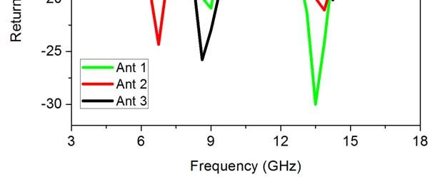
You can also read