Helicopter Emergencies and Hazards
←
→
Page content transcription
If your browser does not render page correctly, please read the page content below
Chapter 11

Helicopter Emergencies
and Hazards
Introduction
Today, helicopters are quite reliable. However, emergencies
do occur, whether a result of mechanical failure or pilot
error, and should be anticipated. Regardless of the cause, the
recovery needs to be quick and precise. By having a thorough
knowledge of the helicopter and its systems, a pilot is able
to handle the situation more readily. Helicopter emergencies
and the proper recovery procedures should be discussed and,
when possible, practiced in flight. In addition, by knowing
the conditions that can lead to an emergency, many potential
accidents can be avoided.

                                                                 11-1
Autorotation                                                         Several factors affect the rate of descent in autorotation:
                                                                     density altitude, gross weight, rotor rpm, and airspeed. The
In a helicopter, an autorotative descent is a power-off
                                                                     primary way to control the rate of descent is with airspeed.
maneuver in which the engine is disengaged from the main
                                                                     Higher or lower airspeed is obtained with the cyclic pitch
rotor system and the rotor blades are driven solely by the
                                                                     control just as in normal powered flight. In theory, a pilot
upward flow of air through the rotor. [Figure 11-1] In other
                                                                     has a choice in the angle of descent varying from a vertical
words, the engine is no longer supplying power to the main
                                                                     descent to maximum range, which is the minimum angle of
rotor.
                                                                     descent. Rate of descent is high at zero airspeed and decreases
                                                                     to a minimum at approximately 50–60 knots, depending upon
The most common reason for an autorotation is failure of the
                                                                     the particular helicopter and the factors just mentioned. As
engine or drive line, but autorotation may also be performed
                                                                     the airspeed increases beyond that which gives minimum rate
in the event of a complete tail rotor failure, since there is
                                                                     of descent, the rate of descent increases again.
virtually no torque produced in an autorotation. In both
areas, maintenance has often been a contributing factor to the
                                                                     When landing from an autorotation, the only energy available
failure. Engine failures are also caused by fuel contamination
                                                                     to arrest the descent rate and ensure a soft landing is the
or exhaustion as well resulting in a forced autorotation.
                                                                     kinetic energy stored in the rotor blades. Tip weights can
                                                                     greatly increase this stored energy. A greater amount of rotor
If the engine fails, the freewheeling unit automatically
                                                                     energy is required to stop a helicopter with a high rate of
disengages the engine from the main rotor allowing the
                                                                     descent than is required to stop a helicopter that is descending
main rotor to rotate freely. Essentially, the freewheeling unit
                                                                     more slowly. Therefore, autorotative descents at very low or
disengages anytime the engine revolutions per minute (rpm)
                                                                     very high airspeeds are more critical than those performed
is less than the rotor rpm.
                                                                     at the minimum rate of descent airspeed.
At the instant of engine failure, the main rotor blades are
                                                                     Each type of helicopter has a specific airspeed and rotor rpm
producing lift and thrust from their angle of attack (AOA)
                                                                     at which a power-off glide is most efficient. The specific
and velocity. By lowering the collective pitch, which must be
                                                                     airspeed is somewhat different for each type of helicopter, but
done immediately in case of an engine failure, lift and drag
                                                                     certain factors affect all configurations in the same manner. In
are reduced, and the helicopter begins an immediate descent,
                                                                     general, rotor rpm maintained in the low green area gives more
thus producing an upward flow of air through the rotor
                                                                     distance in an autorotation. Higher weights may require more
system. This upward flow of air through the rotor provides
                                                                     collective pitch to control rotor rpm. Some helicopters need slight
sufficient thrust to maintain rotor rpm throughout the descent.
                                                                     adjustments to minimum rotor rpm settings for winter versus
Since the tail rotor is driven by the main rotor transmission
                                                                     summer conditions, and high altitude versus sea level flights. For
during autorotation, heading control is maintained with the
                                                                     specific autorotation airspeeds and rotor rpm combinations for a
antitorque pedals as in normal flight.
                                                                     particular helicopter, refer to the Federal Aviation Administration
                                                                     (FAA)-approved rotorcraft flight manual (RFM).

                     Normal Powered Flight                                                       Autorotation
                                                                                               t h
                                                                                             lig

            Direction of flight
                                                                                           f
                                                                                        of
                                                                                        on
                                                                                     cti
                                                                                   re
                                                                                 Di

Figure 11-1. During an autorotation, the upward flow of relative wind permits the main rotor blades to rotate at their normal speed. In
effect, the blades are “gliding” in their rotational plane.

11-2
The specific airspeed and rotor rpm for autorotation is minimal groundspeed. As proficiency increases, the amount
established for each type of helicopter on the basis of of ground run may be reduced.
average weather, wind conditions, and normal loading.
When the helicopter is operated with heavy loads in high Technique
density altitude or gusty wind conditions, best performance Refer to Figure 11-2 (position 1). From level flight at
is achieved from a slightly increased airspeed in the descent. the appropriate airspeed (cruise or the manufacturer’s
For autorotation at low density altitude and light loading, recommended airspeed), 500–700 feet above ground level
best performance is achieved from a slight decrease in (AGL), and heading into the wind, smoothly but firmly
normal airspeed. Following this general procedure of fitting lower the collective pitch control to the full down position,
airspeed and rotor rpm to existing conditions, a pilot can maintaining rotor rpm in the green arc with collective. If
achieve approximately the same glide angle in any set of the collective is in the full down position, the rotor rpm is
circumstances and estimate the touchdown point. then being controlled by the mechanical pitch stops. During
maintenance, the rotor stops must be set to allow minimum
Pilots should practice autorotations with varying airspeeds autorotational rpm with a light loading. This means that some
between the minimum rate of descent to the maximum glide collective pitch adjustment can be made if the air density or
angle airspeed. The decision to use the appropriate airspeed helicopter loading changes. After entering an autorotation,
for the conditions and availability of landing area must be collective pitch must be adjusted to maintain the desired
instinctive. The helicopter glide ratio is much less than that of rotor rpm.
a fixed wing aircraft and takes some getting used to. The flare
to land at 55 KIAS will be significantly different than the flare
from 80 KIAS. Rotor rpm control is critical at these points 1
to ensure adequate rotor energy for cushioning the landing.
Straight-In Autorotation
A straight-in autorotation implies an autorotation from 2
altitude with no turns. Winds have a great effect on an
autorotation. Strong headwinds cause the glide angle to be
steeper due to the slower groundspeed. For example, if the 3
helicopter is maintaining 60 knots indicated airspeed and the
4
wind speed is 15 knots, then the groundspeed is 45 knots. The
angle of descent will be much steeper, although the rate of
descent remains the same. The speed at touchdown and the
resulting ground run depend on the groundspeed and amount 5
of deceleration. The greater the degree of deceleration, or
flare, and the longer it is held, the slower the touchdown speed
and the shorter the ground run. Caution must be exercised Figure 11-2. Straight-in autorotation.
at this point as the tail rotor will be the closest component
of the helicopter to the ground. If timing is not correct and a Coordinate the collective movement with proper antitorque
landing attitude not set at the appropriate time, the tail rotor pedal for trim, and apply cyclic control to maintain proper
may contact the ground causing a forward pitching moment airspeed. Once the collective is fully lowered, decrease
of the nose and possible damage to the helicopter. throttle to ensure a clean split/separation of the needles. This
means that the rotor rpm is higher than the engine rpm and
A headwind is a contributing factor in accomplishing a slow a clear indication that the freewheeling unit has allowed the
touchdown from an autorotative descent and reduces the engine to disconnect. After splitting the needles, readjust
amount of deceleration required. The lower the speed desired the throttle to keep engine rpm above normal idling speed,
at touchdown is, the more accurate the timing and speed of but not high enough to cause rejoining of the needles. The
the flare must be, especially in helicopters with low-inertia manufacturer often recommends the proper rpm for that
rotor systems. If too much collective pitch is applied too particular helicopter.
early during the final stages of the autorotation, the kinetic
energy may be depleted, resulting in little or no cushioning At position 2, adjust attitude with cyclic control to obtain the
effect available. This could result in a hard landing with manufacturer’s recommended autorotation or best gliding
corresponding damage to the helicopter. It is generally better speed. Adjust collective pitch control, as necessary, to
practice to accept more ground run than a hard landing with maintain rotor rpm in the green arc. Aft cyclic movements
11-3cause an increase in rotor rpm, which is then controlled by is required to maintain heading as collective pitch is raised
a small increase in collective pitch control. Avoid a large due to the reduction in rotor rpm and the resulting reduced
collective pitch increase, which results in a rapid decay of effect of the tail rotor. Touch down in a level flight attitude.
rotor rpm, and leads to “chasing the rpm.” Avoid looking
straight down in front of the aircraft. Continually crosscheck Control response with increased pitch angles will be slightly
attitude, trim, rotor rpm, and airspeed. different than normal. With a decrease in main rotor rpm,
the antitorque authority is reduced, requiring larger control
At the altitude recommended by the manufacturer (position inputs to maintain heading at touchdown.
3), begin the flare with aft cyclic control to reduce forward
airspeed and decrease the rate of descent. Maintain heading Some helicopters have a canted tail stabilizer like the
with the antitorque pedals. During the flare maintain rotor rpm Schweitzer 300. It is crucial that the student apply the
in the green range. Care must be taken in the execution of the appropriate pedal input at all times during the autorotation.
flare so that the cyclic control is neither moved rearward so If not the tailboom tends to swing to the right, which allows
abruptly that it causes the helicopter to climb nor moved so the canted stabilizer to raise the tail. This can result in a
slowly that it does not arrest the descent, which may allow severe nose tuck which is quickly corrected with right pedal
the helicopter to settle so rapidly that the tail rotor strikes application.
the ground. In most helicopters, the proper flare attitude is
noticeable by an apparent groundspeed of a slow run. When A power recovery can be made during training in lieu of a full
forward motion decreases to the desired groundspeed, which touchdown landing. Refer to the section on power recovery
is usually the lowest possible speed (position 4), move the for the correct technique. After the helicopter has come to a
cyclic control forward to place the helicopter in the proper complete stop after touchdown, lower the collective pitch to
attitude for landing. the full-down position. Do not try to stop the forward ground
run with aft cyclic, as the main rotor blades can strike the
In many light helicopters, the student pilot can sit in the pilot tail boom. Rather, by lowering the collective slightly during
seat while the instructor pulls down on the helicopter’s tail the ground run, more weight is placed on the undercarriage,
until the tail rotor guard or “stinger” touches the surface. slowing the helicopter.
This action gives the student an idea of airframe attitude to
avoid, because a pilot should never allow ground contact One common error is holding the helicopter off the surface
unless the helicopter is more nose low than that attitude. versus cushioning the helicopter on to the surface during an
Limiting the flare to that pitch attitude may result in slightly autorotation. Holding the helicopter in the air by using all of
faster touchdown speeds, but will eliminate the possibility the rotor rpm potential energy usually causes the helicopter to
of tail rotor impact on level surfaces. have a hard landing, which results in the blades flexing down
and contacting the tail boom. The rotor rpm should be used
The landing gear height at this time should be approximately to cushion the helicopter on to the surface for a controlled,
3–15 feet AGL, depending on the altitude recommended by smooth landing instead of allowing the helicopter to drop
the manufacturer. As the apparent groundspeed and altitude the last few inches.
decrease, the helicopter must be returned to a more level
attitude for touchdown by applying forward cyclic. Some Common Errors
helicopters can be landed on the heels in a slightly nose high
1. Not understanding the importance of an immediate
attitude to help decrease the forward groundspeed whereas
entry into autorotation upon powerplant or driveline
others must land skids or landing gear level to equally spread
failure.
the landing loads to all of the landing gear. Extreme caution
should be used to avoid an excessive nose high and tail low 2. Failing to use sufficient antitorque pedal when power
attitude below 10 feet. The helicopter must be close to the is reduced.
landing attitude to keep the tail rotor from contacting the 3. Lowering the nose too abruptly when power is
surface. reduced, thus placing the helicopter in a dive.
At this point, if a full touchdown landing is to be made, allow 4. Failing to maintain proper rotor rpm during the
the helicopter to descend vertically (position 5). Increase descent.
collective pitch, as necessary, to arrest the descent and 5. Applying up-collective pitch at an excessive altitude,
cushion the landing. This collective application uses some resulting in a hard landing, loss of heading control,
of the potential energy in the rotor system to help slow the and possible damage to the tail rotor and main rotor
descent rate of the helicopter. Additional antitorque pedal blade stops.
11-46. Failing to level the helicopter or achieve the To initiate an autorotation in other than in a low hover, lower
manufacturers preferred landing attitude. the collective pitch control. This holds true whether performing
7. Failure to maintain ground track in the air and keeping a practice autorotation or in the event of an in-flight engine
the landing gear aligned with the direction of travel failure. This reduces the pitch of the main rotor blades and
during touchdown and ground contact. allows them to continue turning at normal rpm. During practice
autorotations, maintain the rpm in the green arc with the throttle
8. Failure to minimize or eliminate lateral movement while lowering collective. Once the collective is fully lowered,
during ground contact. reduce engine rpm by decreasing the throttle. This causes a
9. Failure to go around if not within limits and specified split of the engine and rotor rpm needles.
criteria for safe autorotation.
Technique
Autorotation With Turns The most common types of autorotation are 90° and 180°
A turn, or a series of turns, can be made during an autorotation autorotations. For a 180° autorotation, establish the aircraft
in order to land into the wind or avoid obstacles. The turn is on the downwind at recommended airspeed and 500–700
usually made early so that the remainder of the autorotation feet AGL, parallel to the touchdown area. In a no-wind or
is the same as a straight-in autorotation. Making turns during headwind condition, establish the ground track approximately
an autorotation generally uses cyclic control only. Use of 200 feet away from the touchdown point. If a strong
antitorque pedals to assist or increase the speed of the turn crosswind exists, it is necessary to move the downwind leg
causes loss of airspeed and downward pitching of the nose. closer or farther out. When abeam the intended touchdown
When an autorotation is initiated, sufficient antitorque pedal point, smoothly but firmly lower the collective pitch control
pressure should be used to maintain the helicopter in trim to the full down position, maintaining rotor rpm in the green
and prevent yawing. This pressure should not be changed arc with collective.
to assist the turn. If the helicopter is flown out of trim in
forward flight, the helicopter will be in either a slip or a skid Coordinate the collective movement with proper antitorque
and airframe drag will be greatly increased which in turn pedal for trim, and apply cyclic control to maintain proper
increases the rate of descent. Therefore, for the minimum attitude. Once the collective is fully lowered, decrease throttle
descent vertical speed, the trim ball should remain centered. to ensure a clean split/separation of the needles. After splitting
the needles, readjust the throttle to keep engine rpm above
Use collective pitch control to manage rotor rpm. If rotor rpm normal idling speed, but not high enough to cause rejoining of
builds too high during an autorotation, raise the collective the needles. The manufacturer often recommends the proper
sufficiently to decrease rpm back to the normal operating rpm for that particular helicopter. Crosscheck attitude, trim,
range, then reduce the collective to maintain proper rotor rpm. rotor rpm, and airspeed.
If the collective increase is held too long, the rotor rpm may
decay rapidly. The pilot must then lower the collective and After the descent and airspeed are established, roll into
begin chasing the rotor rpm. If the rpm begins decreasing, the turn. The turn should be approximately 180°, winds
the pilot must again lower the collective. Always keep the may cause the actual turn to be more or less than 180°. For
rotor rpm within the established range for the helicopter being training purposes, initially roll into a bank of a least 30°,
flown. During a turn, rotor rpm increases due to the increased but no more than 50°– 60°. Continuously check airspeed,
G loading, which induces a greater airflow through the rotor rotor rpm, and trim throughout the turn. It is important to
system. The rpm builds rapidly and can easily exceed the maintain the proper airspeed and to keep the aircraft in trim.
maximum limit if not controlled by use of collective. The Changes in the aircraft’s attitude and the angle of bank cause
tighter the turn is and the heavier the gross weight is, the a corresponding change in rotor rpm. Adjust the collective, as
higher the rpm is. necessary, in the turn to maintain rotor rpm in the green arc.
Cyclic input has a great effect on the rotor rpm. An aft cyclic At the 90° point, check the progress of the turn by glancing
input loads the rotor, resulting in coning and an increase in toward the landing area. Plan the second 90 degrees of turn
rotor rpm. A forward cyclic input unloads the rotor, resulting to roll out on the centerline. If the helicopter is too close,
in a decrease in rotor rpm. Therefore, it is prudent to attain decrease the bank angle; if too far out, increase the bank
the proper pitch attitude needed to ensure that the desired angle. Adjusting the bank angle will change the G loading,
landing area can be reached as soon as possible, and to make which in turn alters the airflow and results in rotor rpm
minor adjustments from there. changes. Keep the helicopter in trim with antitorque pedals.
11-5The turn should be completed and the helicopter aligned with flight setting at the beginning of the flare. As the rotor system
the intended touchdown area prior to passing through 100 begins to dissipate its energy, the engine is up to speed as
feet AGL. If the collective pitch was temporarily increased the needles join when the rotor decreases into the normal
to control the rpm, it may need to be lowered on rollout to flight rpm.
prevent decay in rpm. Make an immediate power recovery
if the aircraft is not aligned with the touchdown point, and Helicopters that do not have the throttle control located on the
if the rotor rpm and/or airspeed are not within proper limits. collective require some additional prudence. The autorotation
Otherwise, complete the procedure as if it were a straight-in should be initiated with the power levers left in the “flight,”
autorotation. or normal, position. If a full touchdown is to be practiced, it
is common technique to move the power levers to the idle
Common Errors position once the landing area can safely be reached. In most
helicopters, the pilot is fully committed at that point to make
1. Failure to maintain trim during the turn (increases rate
a power-off landing. However, it may be possible to make
of descent).
a power recovery prior to passing through 100 feet AGL if
2. Failure to maintain autorotation airspeed. the powerplant can recover within that time period and the
3. Failure to hold proper pitch attitude for type helicopter instructor is very proficient. The pilot should comply with
(too high or too low). the RFM instructions in all cases.
4. Failure to have proper alignment with touchdown zone When practicing autorotations to a power recovery, the
by 100 feet AGL. differences between reciprocating engines and turbines
5. Failure to maintain rotor rpm within limits during the may be profound. The reciprocating powerplant generally
maneuver. responds very quickly to power changes, especially power
6. Failure to go around if not within limits and specified increases. Some turbines have delay times depending on
criteria for safe autorotation. the type of fuel control or governing system installed. Any
reciprocating engine needing turbocharged boost to develop
Practice Autorotation With a Power Recovery rated horse power may have significant delays to demands
for increased power, such as in the power recovery. Power
A power recovery is used to terminate practice autorotations
recovery in those helicopters with slower engine response
at a point prior to actual touchdown. After the power
times must have the engines begin to develop enough power
recovery, a landing can be made or a go-around initiated.
to rejoin the needles by approximately 100 feet AGL.
Technique
If a go-around is to be made, the cyclic control should be
At approximately 3–15 feet landing gear height AGL, moved forward to resume forward flight. In transition from
depending upon the helicopter being used, begin to level the a practice autorotation to a go-around, exercise caution to
helicopter with forward cyclic control. Avoid excessive nose- avoid an altitude-airspeed combination that would place the
high, tail-low attitude below 10 feet. Just prior to achieving helicopter in an unsafe area of its height-velocity diagram.
level attitude, with the nose still slightly up, coordinate
upward collective pitch control with an increase in the
This is one of the most difficult maneuvers to perform due to
throttle to join the needles at operating rpm. The throttle and the concentration needed when transitioning from powered
collective pitch must be coordinated properly. flight to autorotation and then back again to powered flight.
For helicopters equipped with the power control on the
If the throttle is increased too fast or too much, an engine collective, engine power must be brought from flight power
overspeed can occur; if throttle is increased too slowly or to idle power and then back to a flight power setting. A delay
too little in proportion to the increase in collective pitch, a during any of these transitions can seriously affect rotor rpm
loss of rotor rpm results. Use sufficient collective pitch to placing the helicopter in a situation that cannot be recovered.
stop the descent, but keep in mind that the collective pitch
application must be gradual to allow for engine response. The cyclic must be adjusted to maintain the required
Coordinate proper antitorque pedal pressure to maintain airspeed without power, and then used for the deceleration
heading. When a landing is to be made following the power flare, followed by the transition to level hovering flight.
recovery, bring the helicopter to a hover at hovering altitude Additionally, the cyclic must be adjusted to remove the
and then descend to a landing. compensation for translating tendency. The tail rotor is
no longer needed to produce antitorque thrust until almost
When practicing autorotations with power recovery in nearly
all helicopters, the throttle or power levers should be at the
11-6maximum power is applied to the rotor system for hovering necessary to keep the helicopter from drifting to the left, to
flight, when the tail rotor must again compensate for the main compensate for the loss of tail rotor thrust. However, use
rotor torque, which also demands compensation for the tail cyclic control, as required, to ensure a vertical descent and
rotor thrust and translating tendency. a level attitude. Do not adjust the collective pitch on entry.
The pedals must be adjusted from a powered flight anti- Helicopters with low inertia rotor systems settle immediately.
torque trim setting to the opposite trim setting to compensate Keep a level attitude and ensure a vertical descent with
for transmission drag and any unneeded vertical fin thrust cyclic control while maintaining heading with the pedals.
countering the now nonexistent torque and then reset to Any lateral movement must be avoided to prevent dynamic
compensate for the high power required for hovering flight. rollover. As rotor rpm decays, cyclic response decreases,
so compensation for winds will change, requiring more
All of the above must be accomplished during the 23 seconds cyclic input. At approximately 1 foot AGL, apply upward
of the autorotation and the tedious control inputs must be collective pitch control, as necessary, to slow the descent
made in the last 5 seconds of the maneuver. and cushion the landing without arresting the rate of descent
above the surface. Usually, the full amount of collective pitch
Common Errors is required just as the landing gear touches the surface. As
upward collective pitch control is applied, the throttle must
1. Initiating recovery too late, which requires a rapid
be held in the idle detent position to prevent the engine from
application of controls and results in overcontrolling.
re-engaging.
2. Failure to obtain and maintain a level attitude near the
surface. Helicopters with high inertia rotor systems settle more slowly
3. Failure to coordinate throttle and collective pitch after the throttle is closed. When the helicopter has settled
properly, which results in either an engine overspeed to approximately 1 foot AGL, apply upward collective pitch
or a loss of rotor rpm. control while holding the throttle in the idle detent position
to slow the descent and cushion the landing. The timing of
4. Failure to coordinate proper antitorque pedal with the collective pitch control application and the rate at which it is
increase in power. applied depend upon the particular helicopter being used, its
5. Late engine power engagement causing excessive gross weight, and the existing atmospheric conditions. Cyclic
temperatures or torques, or rpm droop. control is used to maintain a level attitude and to ensure a
6. Failure to go around if not within limits and specified vertical descent. Maintain heading with antitorque pedals.
criteria for safe autorotation.
When the weight of the helicopter is entirely resting on
the landing gear, cease application of upward collective.
Power Failure in a Hover When the helicopter has come to a complete stop, lower the
Power failure in a hover, also called hovering autorotation, is collective pitch to the full-down position.
practiced so that a pilot can automatically make the correct
response when confronted with engine stoppage or certain The timing of the collective pitch is a most important
other emergencies while hovering. The techniques discussed consideration. If it is applied too soon, the remaining rpm
in this section are for helicopters with a counterclockwise may not be sufficient to make a soft landing. On the other
rotor system and an antitorque rotor. hand, if collective pitch control is applied too late, surface
contact may be made before sufficient blade pitch is available
Technique to cushion the landing. The collective must not be used to
To practice hovering autorotation, establish a normal hold the helicopter off the surface, causing a blade stall. Low
hovering altitude (approximately 2–3 feet) for the particular rotor rpm and ensuing blade stall can result in a total loss
helicopter being used, considering load and atmospheric of rotor lift allowing the helicopter to fall to the surface and
conditions. Keep the helicopter headed into the wind and possibly resulting in blade strikes to the tail boom and other
hold maximum allowable rpm. airframe damage such as landing gear damage, transmission
mount deformation, and fuselage cracking.
To simulate a power failure, firmly roll the throttle to the
engine idle position. This disengages the driving force of the Common Errors
engine from the rotor, thus eliminating torque effect. As the
1. Failure to use sufficient proper antitorque pedal when
throttle is closed, apply proper antitorque pedal to maintain
power is reduced.
heading. Usually, a slight amount of right cyclic control is
11-72. Failure to stop all sideward or backward movement In the simplest explanation, the H/V curve is a diagram in
prior to touchdown. which the shaded areas should be avoided, as the pilot may be
3. Failure to apply up-collective pitch properly, resulting unable to complete an autorotation landing without damage.
in a hard touchdown. The H/V curve usually contains a takeoff profile, where the
diagram can be traversed from 0 height and 0 speed to cruise,
4. Failure to touch down in a level attitude. without entering the shaded areas or with minimum exposure
5. Failure to roll the throttle completely to idle. to shaded areas.
6. Failure to hover at a safe altitude for the helicopter
The portion in the upper left of this diagram demonstrates
type, atmospheric conditions, and the level of training/
a flight profile that probably does not allow the pilot to
proficiency of the pilot.
complete an autorotation successfully, primarily due to
7. Failure to go around if not within limits and specified having insufficient airspeed to enter an autorotative profile
criteria for safe autorotation. in time to avoid a crash. The shaded area on the lower right
is dangerous due to the airspeed and proximity to the ground
Height/Velocity Diagram resulting in dramatically reduced reaction time for the pilot in
The height/velocity diagram or H/V curve is a graph charting the case of mechanical failure, or other in-flight emergencies.
the safe/unsafe flight profiles relevant to a specific helicopter. This shaded area at the lower right is not portrayed in H/V
As operation outside the safe area of the chart can be fatal curves for multi-engine helicopters capable of safely hovering
in the event of a power or driveline failure, it is sometimes and flying with a single engine failure.
referred to as the dead man’s curve by helicopter pilots. By
carefully studying the height/velocity diagram, a pilot is The following examples further illustrate the relevance of
able to avoid the combinations of altitude and airspeed that the H/V curve to a single-engine helicopter.
may not allow sufficient time or altitude to enter a stabilized
autorotative descent. A pilot may want to refer to this diagram At low heights with low airspeed, such as a hover taxi, the
during the remainder of the discussion on the height/velocity pilot can simply use the potential energy from the rotor
diagram. [Figure 11-3] system to cushion the landing with collective, converting
rotational inertia to lift. The aircraft is in a safe part of the
500 H/V curve. At the extreme end of the scale (e.g., a three-
foot hover taxi at walking pace) even a complete failure to
450 recognize the power loss resulting in an uncushioned landing
would probably be survivable.
400 Avoid operation in shaded areas
As the airspeed increases without an increase in height,
350 there comes a point at which the pilot’s reaction time would
be insufficient to react with a flare in time to prevent a high
Height above surface (feet)
Smooth hard surface
300 speed, and thus probably fatal, ground impact. Another thing
to consider is the length of the tailboom and the response
250 time of the helicopter flight controls at slow airspeeds and
low altitudes. Even small increases in height give the pilot
200 A much greater time to react; therefore, the bottom right part
of the H/V curve is usually a shallow gradient. If airspeed is
150
above ideal autorotation speed, the pilot’s instinct is usually
to flare to convert speed to height and increase rotor rpm
through coning, which also immediately gets them out of
100
the dead man’s curve.
50
B Conversely, an increase in height without a corresponding
increase in airspeed puts the aircraft above a survivable
0
0 10 20 30 40 50 60 70 80 90 100 uncushioned impact height, and eventually above a height
Indicated airspeed (knots) where rotor inertia can be converted to sufficient lift to enable
(corrected for instrument error) a survivable landing. This occurs abruptly with airspeeds
much below the ideal autorotative speed (typically 40–80
knots). The pilot must have enough time to accelerate to
Figure 11-3. Height/velocity diagram.
11-8autorotation speed in order to autorotate successfully; this provide a restriction to gross weight, but to be an advisory of
directly relates to a requirement for height. Above a certain the autorotative capability of the helicopter during takeoff and
height the pilot can achieve autorotation speed even from a climb. A pilot must realize, however, that at gross weights
0 knot start, thus putting high OGE hovers outside the curve. above those recommended by the gross weight versus density
altitude chart, the values are unknown.
The typical safe takeoff profile involves initiation of forward
flight from a 2–3 feet landing gear height, only gaining Assuming a density altitude of 5,500 feet, the height/velocity
altitude as the helicopter accelerates through translational lift diagram in Figure 11-3 would be valid up to a gross weight
and airspeed approaches a safe autorotative speed. At this of approximately 1,700 pounds. This is found by entering
point, some of the increased thrust available may be used to the graph in Figure 11-4 at a density altitude of 5,500 feet
attain safe climb airspeed and will keep the helicopter out of (point A), then moving horizontally to the solid line (point
the shaded or hatched areas of the H/V diagram. Although B). Moving vertically to the bottom of the graph (point C),
helicopters are not restricted from conducting maneuvers with the existing density altitude, the maximum gross weight
that will place them in the shaded area of the H/V chart, it under which the height/velocity diagram is applicable is
is important for pilots to understand that operation in those 1,700 pounds.
shaded areas exposes pilot, aircraft, and passengers to a
certain hazard should the engine or driveline malfunction. Charts and diagrams for helicopters set out in Title 14 of the
The pilot should always evaluate the risk of the maneuver Code of Federal Regulations (14 CFR) Part 27, Airworthiness
versus the operational value. Standards: Normal Category Rotorcraft, are advisory in nature
and not regulatory. However, these charts do establish the safe
The Effect of Weight Versus Density Altitude parameters for operation. It is important to remember these
The height/velocity diagram [Figure 11-3] depicts altitude guidelines establish the tested capabilities of the helicopter.
and airspeed situations from which a successful autorotation Unless the pilot in command (PIC) is a certificated test pilot,
can be made. The time required, and therefore, altitude operating a helicopter beyond its established capabilities can
necessary to attain a steady state autorotative descent, is be considered careless and reckless operation, especially if
dependent on the weight of the helicopter and the density this action results is death or injury.
altitude. For this reason, the H/V diagram is valid only when
the helicopter is operated in accordance with the gross weight Common Errors
versus density altitude chart. If published, this chart is found 1. Performing hovers higher than performed during
in the RFM for the particular helicopter. [Figure 11-4] The training for hovering autorotations and practiced
gross weight versus density altitude chart is not intended to proficiency.
2. Excessively nose-low takeoffs. The forward landing
7 gear would impact before the pilot could assume a
landing attitude.
3. Adding too much power for takeoff.
Density altitude (thousands of feet)
6 4. Not maintaining landing gear aligned with takeoff
path until transitioning to a crab heading to account
B
for winds.
A
5 Settling With Power (Vortex Ring State)
Vortex ring state describes an aerodynamic condition in
which a helicopter may be in a vertical descent with 20
4
percent up to maximum power applied, and little or no climb
performance. The term “settling with power” comes from
the fact that the helicopter keeps settling even though full
engine power is applied.
C
3
1,500 1,600 1,700 1,800 1,900 2,000 In a normal out-of-ground-effect (OGE) hover, the helicopter
Gross weight (pounds) is able to remain stationary by propelling a large mass of air
down through the main rotor. Some of the air is recirculated
near the tips of the blades, curling up from the bottom of the
Figure 11-4. Gross weight versus density altitude.
11-9rotor system and rejoining the air entering the rotor from The following combination of conditions is likely to cause
the top. This phenomenon is common to all airfoils and is settling in a vortex ring state in any helicopter:
known as tip vortices. Tip vortices generate drag and degrade 1. A vertical or nearly vertical descent of at least 300
airfoil efficiency. As long as the tip vortices are small, their fpm. (Actual critical rate depends on the gross weight,
only effect is a small loss in rotor efficiency. However, when rpm, density altitude, and other pertinent factors.)
the helicopter begins to descend vertically, it settles into its
own downwash, which greatly enlarges the tip vortices. In 2. The rotor system must be using some of the available
this vortex ring state, most of the power developed by the engine power (20–100 percent).
engine is wasted in circulating the air in a doughnut pattern 3. The horizontal velocity must be slower than effective
around the rotor. translational lift.
In addition, the helicopter may descend at a rate that exceeds Some of the situations that are conducive to a settling with
the normal downward induced-flow rate of the inner blade power condition are: any hover above ground effect altitude,
sections. As a result, the airflow of the inner blade sections is specifically attempting to hover OGE at altitudes above the
upward relative to the disk. This produces a secondary vortex hovering ceiling of the helicopter, attempting to hover OGE
ring in addition to the normal tip vortices. The secondary without maintaining precise altitude control, pinnacle or
vortex ring is generated about the point on the blade where the rooftop helipads when the wind is not aligned with the landing
airflow changes from up to down. The result is an unsteady direction, and downwind and steep power approaches in
turbulent flow over a large area of the disk. Rotor efficiency which airspeed is permitted to drop below 10 knots depending
is lost even though power is still being supplied from the on the type of helicopter.
engine. [Figure 11-5]
When recovering from a settling with power condition,
the pilot tends first to try to stop the descent by increasing
collective pitch. However, this only results in increasing
the stalled area of the rotor, thereby increasing the rate of
descent. Since inboard portions of the blades are stalled,
cyclic control may be limited. Recovery is accomplished
by increasing airspeed, and/or partially lowering collective
pitch. In many helicopters, lateral cyclic combined with
lateral tailrotor thrust will produce the quickest exit from the
hazard assuming that there are no barriers in that direction.
In a fully developed vortex ring state, the only recovery may
be to enter autorotation to break the vortex ring state.
Tandem rotor helicopters should maneuver laterally to
achieve clean air in both rotors at the same time.
Figure 11-5. Vortex ring state. For settling with power demonstrations and training in
recognition of vortex ring state conditions, all maneuvers
A fully developed vortex ring state is characterized by an should be performed at an altitude of 2000–3000 feet AGL
unstable condition in which the helicopter experiences to allow sufficient altitude for entry and recovery.
uncommanded pitch and roll oscillations, has little or no
collective authority, and achieves a descent rate that may To enter the maneuver, come to an OGE hover, maintaining
approach 6,000 feet per minute (fpm) if allowed to develop. little or no airspeed (any direction), decrease collective
to begin a vertical descent, and as the turbulence begins,
A vortex ring state may be entered during any maneuver increase collective. Then allow the sink rate to increase to 300
that places the main rotor in a condition of descending in a fpm or more as the attitude is adjusted to obtain airspeed of
column of disturbed air and low forward airspeed. Airspeeds less than 10 knots. When the aircraft begins to shudder, the
that are below translational lift airspeeds are within this application of additional up collective increases the vibration
region of susceptibility to settling with power aerodynamics. and sink rate. As the power is increased, the rate of sink of
This condition is sometimes seen during quick-stop type the aircraft in the column of air will increase.
maneuvers or during recovery from autorotation.
11-10If altitude is sufficient, some time can be spent in the Common Errors
vortices, to enable the pilot to develop a healthy knowledge
1. Failure to recognize the combination of contributing
of the maneuver. However, helicopter pilots would normally
factors leading to retreating blade stall.
initiate recovery at the first indication of settling with power.
Recovery should be initiated at the first sign of vortex ring 2. Failure to compute VNE limits for altitudes to be flown.
state by applying forward cyclic to increase airspeed and/ or
simultaneously reducing collective. The recovery is complete Ground Resonance
when the aircraft passes through effective translational lift Helicopters with articulating rotors (usually designs with
and a normal climb is established. three or more main rotor blades) are subject to ground
resonance, a destructive vibration phenomenon that occurs
Common Errors at certain rotor speeds when the helicopter is on the ground.
1. Too much lateral speed for entry into settling with Ground resonance is a mechanical design issue that results
power. from the helicopter’s airframe having a natural frequency that
can be intensified by an out-of-balance rotor. The unbalanced
2. Excessive decrease of collective pitch. rotor system vibrates at the same frequency or multiple of the
airframe’s resonant frequency and the harmonic oscillation
Retreating Blade Stall increases because the engine is adding power to the system,
In forward flight, the relative airflow through the main rotor increasing the magnitude (or amplitude) of the vibrations
disk is different on the advancing and retreating side. The until the structure or structures fail. This condition can cause
relative airflow over the advancing side is higher due to the a helicopter to self-destruct in a matter of seconds.
forward speed of the helicopter, while the relative airflow on
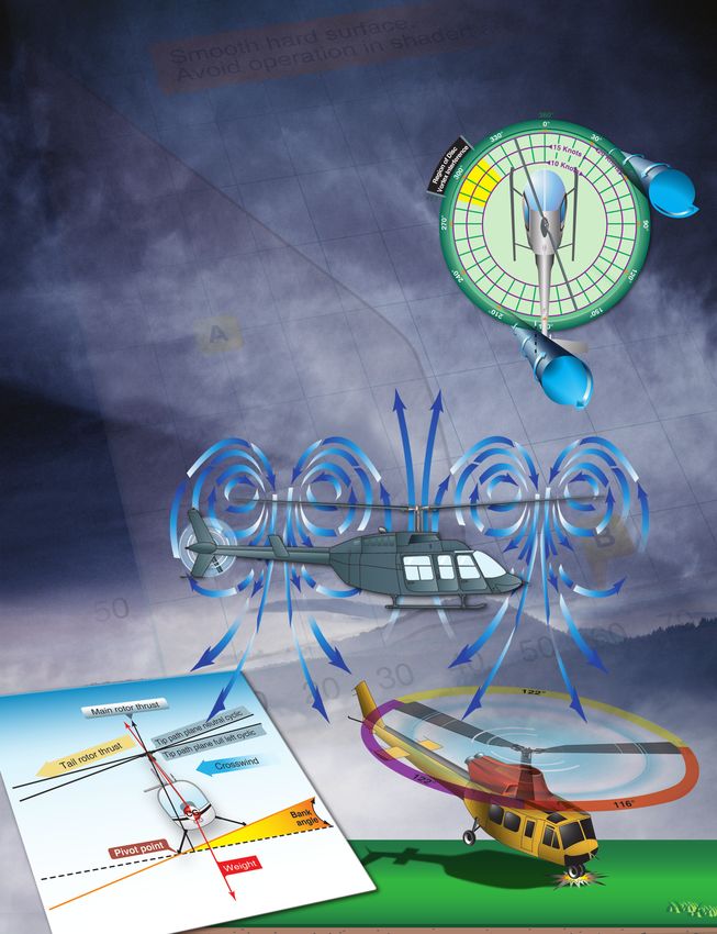
the retreating side is lower. This dissymmetry of lift increases Hard contact with the ground on one corner (and usually
as forward speed increases. with wheel-type landing gear) can send a shockwave to the
main rotor head, resulting in the blades of a three-blade rotor
To generate the same amount of lift across the rotor disk, system moving from their normal 120° relationship to each
the advancing blade flaps up while the retreating blade flaps other. This movement occurs along the drag hinge and could
down. This causes the AOA to decrease on the advancing result in something like 122°, 122°, and 116° between blades.
blade, which reduces lift, and increase on the retreating blade, [Figure 11-6] When one of the other landing gear strikes the
which increases lift. At some point as the forward speed surface, the unbalanced condition could be further aggravated.
increases, the low blade speed on the retreating blade, and If the rpm is low, the only corrective action to stop ground
its high AOA cause a stall and loss of lift. resonance is to close the throttle immediately and fully lower
the collective to place the blades in low pitch. If the rpm is in
Retreating blade stall is a major factor in limiting a the normal operating range, fly the helicopter off the ground,
helicopter’s never-exceed speed (VNE) and its development
can be felt by a low frequency vibration, pitching up of the
nose, and a roll in the direction of the retreating blade. High
weight, low rotor rpm, high density altitude, turbulence and/
or steep, abrupt turns are all conducive to retreating blade 122°
stall at high forward airspeeds. As altitude is increased, higher
blade angles are required to maintain lift at a given airspeed.
Thus, retreating blade stall is encountered at a lower forward
airspeed at altitude. Most manufacturers publish charts and 12
2°
graphs showing a VNE decrease with altitude.
116°
When recovering from a retreating blade stall condition,
moving the cyclic aft only worsens the stall as aft cyclic
produces a flare effect, thus increasing the AOA. Pushing
forward on the cyclic also deepens the stall as the AOA on the
retreating blade is increased. Correct recovery from retreating
blade stall requires the collective to be lowered first, which
reduces blade angles and thus AOA. Aft cyclic can then be
used to slow the helicopter.
Figure 11-6. Ground resonance.
11-11and allow the blades to rephase themselves automatically. force that rolls the helicopter over. When limited rotor blade
Then, make a normal touchdown. If a pilot lifts off and allows movement is coupled with the fact that most of a helicopter’s
the helicopter to firmly re-contact the surface before the weight is high in the airframe, another element of risk is added
blades are realigned, a second shock could move the blades to an already slightly unstable center of gravity. Pilots must
again and aggravate the already unbalanced condition. This remember that in order to remove thrust, the collective must
could lead to a violent, uncontrollable oscillation. be lowered as this is the only recovery technique available.
This situation does not occur in rigid or semi-rigid rotor Critical Conditions
systems because there is no drag hinge. In addition, skid-type Certain conditions reduce the critical rollover angle, thus
landing gear is not as prone to ground resonance as wheel- increasing the possibility for dynamic rollover and reducing
type landing gear since the rubber tires are not present and the chance for recovery. The rate of rolling motion is also
change the rebound characteristics. a consideration because, as the roll rate increases, there is
a reduction of the critical rollover angle at which recovery
Dynamic Rollover is still possible. Other critical conditions include operating
A helicopter is susceptible to a lateral rolling tendency, called at high gross weights with thrust (lift) approximately equal
dynamic rollover, when the helicopter is in contact with the to the weight.
surface during takeoffs or landings. For dynamic rollover to
occur, some factor must first cause the helicopter to roll or Refer to Figure 11-7. The following conditions are most
pivot around a skid or landing gear wheel, until its critical critical for helicopters with counterclockwise rotor rotation:
rollover angle is reached. (5–8° depending on helicopter, 1. Right side skid or landing wheel down, since
winds, and loading) Then, beyond this point, main rotor translating tendency adds to the rollover force.
thrust continues the roll and recovery is impossible. After this
2. Right lateral center of gravity (CG).
angle is achieved, the cyclic does not have sufficient range
of control to eliminate the thrust component and convert it to 3. Crosswinds from the left.
lift. If the critical rollover angle is exceeded, the helicopter 4. Left yaw inputs.
rolls on its side regardless of the cyclic corrections made.
Dynamic rollover begins when the helicopter starts to pivot
laterally around its skid or wheel. This can occur for a variety Main rotor thrust
of reasons, including the failure to remove a tie down or
skid-securing device, or if the skid or wheel contacts a fixed utral c
yclic
pla ne ne
object while hovering sideward, or if the gear is stuck in ip-path
hrust T
otor t ft cyclic
ice, soft asphalt, or mud. Dynamic rollover may also occur Tail r Tip-path pl
ane full le
if you use an improper landing or takeoff technique or while
performing slope operations. Whatever the cause, if the gear Crosswind
or skid becomes a pivot point, dynamic rollover is possible
if not using the proper corrective technique.
CG
Once started, dynamic rollover cannot be stopped by Bank
Pivot point angle
application of opposite cyclic control alone. For example,
the right skid contacts an object and becomes the pivot Weight
point while the helicopter starts rolling to the right. Even
with full left cyclic applied, the main rotor thrust vector and
its moment follows the aircraft as it continues rolling to the
right. Quickly reducing collective pitch is the most effective Figure 11-7. Forces acting on a helicopter with right skid on the
way to stop dynamic rollover from developing. Dynamic ground.
rollover can occur with any type of landing gear and all types
of rotor systems. For helicopters with clockwise rotor rotation, the opposite
conditions would be true.
It is important to remember rotor blades have a limited range
of movement. If the tilt or roll of the helicopter exceeds that
range (5–8°), the controls (cyclic) can no longer command a
vertical lift component and the thrust or lift becomes a lateral
11-12Cyclic Trim
When maneuvering with one skid or wheel on the ground, Full opposite cyclic limit
to prevent rolling motion
care must be taken to keep the helicopter cyclic control
carefully adjusted. For example, if a slow takeoff is attempted
and the cyclic is not positioned and adjusted to account for
t
r thrus
translating tendency, the critical recovery angle may be Tail roto
exceeded in less than two seconds. Control can be maintained
if the pilot maintains proper cyclic position, and does not
allow the helicopter’s roll and pitch rates to become too
great. Fly the helicopter into the air smoothly while keeping Area
of crit
movements of pitch, roll, and yaw small; do not allow any ical ro
llover Slope
abrupt cyclic pressures.
Horizontal
Normal Takeoffs and Landings
Dynamic rollover is possible even during normal takeoffs
and landings on relatively level ground, if one wheel or Figure 11-8. Upslope rolling motion.
skid is on the ground and thrust (lift) is approximately equal
to the weight of the helicopter. If the takeoff or landing is seconds, may be adequate to stop the rolling motion. Take
not performed properly, a roll rate could develop around care, however, not to dump collective at an excessively
the wheel or skid that is on the ground. When taking off or high rate, as this may cause a main rotor blade to strike the
landing, perform the maneuver smoothly and carefully adjust fuselage. Additionally, if the helicopter is on a slope and the
the cyclic so that no pitch or roll movement rates build up, roll starts toward the upslope side, reducing collective too fast
especially the roll rate. If the bank angle starts to increase to may create a high roll rate in the opposite direction. When
an angle of approximately 5–8°, and full corrective cyclic the upslope skid or wheel hits the ground, the dynamics of
does not reduce the angle, the collective should be reduced the motion can cause the helicopter to bounce off the upslope
to diminish the unstable rolling condition. Excessive bank skid or wheel, and the inertia can cause the helicopter to roll
angles can also be caused by landing gear caught in a tie about the downslope ground contact point and over on its
down strap, or a tie down strap still attached to one side of side. [Figure 11-9]
the helicopter. Lateral loading imbalance (usually outside
published limits) is another contributing factor. Full opposite cyclic limit
to prevent rolling motion
Slope Takeoffs and Landings
During slope operations, excessive application of cyclic
t
control into the slope, together with excessive collective pitch r thrus
Tail roto
control, can result in the downslope skid or landing wheel
rising sufficiently to exceed lateral cyclic control limits, and
an upslope rolling motion can occur. [Figure 11-8]
er
llov
tical ro
When performing slope takeoff and landing maneuvers, ao f cri
Are Slope
follow the published procedures and keep the roll rates
small. Slowly raise the downslope skid or wheel to bring the
Horizontal
helicopter level, and then lift off. During landing, first touch
down on the upslope skid or wheel, then slowly lower the
downslope skid or wheel using combined movements of cyclic
and collective. If the helicopter rolls approximately 5–8° to the Figure 11-9. Downslope rolling motion.
upslope side, decrease collective to correct the bank angle and
return to level attitude, then start the landing procedure again.
Under normal conditions, the collective should not be pulled
Use of Collective suddenly to get airborne because a large and abrupt rolling
The collective is more effective in controlling the rolling moment in the opposite direction could occur. Excessive
motion than lateral cyclic, because it reduces the main rotor application of collective can result in the upslope skid or
thrust (lift). A smooth, moderate collective reduction, at a wheel rising sufficiently to exceed lateral cyclic control
rate of less than approximately full up to full down in two limits. This movement may be uncontrollable. If the
11-13helicopter develops a roll rate with one skid or wheel on the skid or wheel starts to leave the ground before the
ground, the helicopter can roll over on its side. downslope skid or wheel, smoothly and gently lower
the collective and check to see if the downslope skid or
Precautions wheel is caught on something. Under these conditions,
To help avoid dynamic rollover: vertical ascent is the only acceptable method of lift-off.
1. Always practice hovering autorotations into the wind, 12. Be aware that dynamic rollover can be experienced
and be wary when the wind is gusty or greater than 10 during flight operations on a floating platform if the
knots. platform is pitching/rolling while attempting to land
or takeoff. Generally, the pilot operating on floating
2. Use extreme caution when hovering close to fences,
platforms (barges, ships, etc.) observes a cycle of
sprinklers, bushes, runway/taxi lights, tiedown cables,
seven during which the waves increase and then
deck nets, or other obstacles that could catch a skid
decrease to a minimum. It is that time of minimum
or wheel. Aircraft parked on hot asphalt over night
wave motion that the pilot needs to use for the moment
might find the landing gear sunk in and stuck as the
of landing or takeoff on floating platforms. Pilots
ramp cooled during the evening.
operating from floating platforms should also exercise
3. Always use a two-step lift-off. Pull in just enough great caution concerning cranes, masts, nearby boats
collective pitch control to be light on the skids or (tugs) and nets.
landing wheels and feel for equilibrium, then gently
lift the helicopter into the air. Low-G Conditions and Mast Bumping
4. Hover high enough to have adequate skid or landing Low acceleration of gravity (low-G or weightless) maneuvers
wheel clearance with any obstacles when practicing create specific hazards for helicopters, especially those with
hovering maneuvers close to the ground, especially semirigid main rotor systems because helicopters are primarily
when practicing sideways or rearward flight. designed to be suspended from the main rotor in normal flight
5. Remember that when the wind is coming from with only small variations for positive G load maneuvers.
the upslope direction, less lateral cyclic control is Since a helicopter low-G maneuver departs from normal
available. flight conditions, it may allow the airframe to exceed the
manufacturer’s design criteria. A low-G condition could have
6. Avoid tailwind conditions when conducting slope
disastrous results, the best way to prevent it from happening is
operations.
to avoid the conditions in which it might occur.
7. Remember that less lateral cyclic control is available
due to the translating tendency of the tail rotor when Low-G conditions are not about the loss of thrust, rather the
the left skid or landing wheel is upslope. (This is true imbalance of forces. Helicopters are mostly designed to have
for counterclockwise rotor systems.) weight (gravity pulling down to the earth) and lift opposing
8. Keep in mind that the lateral cyclic requirement that force of gravity. Low-G maneuvers occur when this
changes when passengers or cargo are loaded or balance is disturbed. An example of this would be placing the
unloaded. helicopter into a very steep dive. At the moment of pushover,
the lift and thrust of the rotor is forward, whereas gravity
9. Be aware that if the helicopter utilizes interconnecting
is now vertical or straight down. Since the lift vector is no
fuel lines that allow fuel to automatically transfer from
longer vertical and opposing the gravity (or weight) vector,
one side of the helicopter to the other, the gravitational
the fuselage is now affected by the tail rotor thrust below the
flow of fuel to the downslope tank could change the
plane of the main rotor. This tail rotor thrust moment tends to
CG, resulting in a different amount of cyclic control
make the helicopter fuselage tilt to the left. Pilots then apply
application to obtain the same lateral result.
right cyclic inputs to try to correct for the left. Since the main
10. Do not allow the cyclic limits to be reached. If the rotor system does not fully support the fuselage at this point,
cyclic control limit is reached, further lowering of the the fuselage continues to roll and the pilot applies more right
collective may cause mast bumping. If this occurs, cyclic until the rotor system strikes the mast (mast bumping),
return to a hover and select a landing point with a often ending with unnecessary fatal results. In mast bumping,
lesser degree of slope. the rotor blade exceeds its flapping limits, causing the main
11. During a takeoff from a slope, begin by leveling the rotor hub to “bump” into the rotor shaft. [Figure 11-10] The
main rotor disk with the horizon or very slightly into main rotor hub’s contact with the mast usually becomes more
the slope to ensure vertical lift and only enough lateral violent with each successive flapping motion. This creates a
thrust to prevent sliding on the slope. If the upslope greater flapping displacement and leads to structural failure of
11-14You can also read