HGCN: HARMONIC GATED COMPENSATION NETWORK FOR SPEECH ENHANCEMENT
←
→
Page content transcription
If your browser does not render page correctly, please read the page content below
HGCN: HARMONIC GATED COMPENSATION NETWORK FOR SPEECH ENHANCEMENT

                                                                Tianrui Wang?† , Weibin Zhu? , Yingying Gao† , Junlan Feng† , Shilei Zhang†
                                                            ?
                                                                Institute of Information Science, Beijing Jiaotong University, Beijing, China
                                                                              †
                                                                                China Mobile Research Institute, Beijing, China

                                                                    ABSTRACT                                  by noise, the pitch predicted by spectral integral is reliable.
arXiv:2201.12755v1 [eess.AS] 30 Jan 2022

                                                                                                              However, i) the frequency resolution after STFT in the deep
                                           Mask processing in the time-frequency (T-F) domain through
                                                                                                              learning model is fixed and low, which causes the prediction
                                           the neural network has been one of the mainstreams for
                                                                                                              of the pitch by the former spectral integral to be less accurate.
                                           single-channel speech enhancement. However, it is hard for
                                                                                                              And ii) the magnitude values that need to be compensated in
                                           most models to handle the situation when harmonics are par-
                                                                                                              the harmonic locations are difficult to be obtained [10, 11].
                                           tially masked by noise. To tackle this challenge, we propose
                                                                                                                   In this paper, a harmonic gated compensation network
                                           a harmonic gated compensation network (HGCN). We de-
                                                                                                              (HGCN) is proposed. To tackle challenge i), we increase
                                           sign a high-resolution harmonic integral spectrum to improve
                                                                                                              the resolution of the pitch candidates and propose a high-
                                           the accuracy of harmonic locations prediction. Then we add
                                                                                                              resolution harmonic integral spectrum. To tackle challenge
                                           voice activity detection (VAD) and voiced region detection
                                                                                                              ii), we design a gated [12] compensation module to adjust the
                                           (VRD) to the convolutional recurrent network (CRN) to filter
                                                                                                              magnitude of harmonic. In addition, we design a speech en-
                                           harmonic locations. Finally, the harmonic gating mechanism
                                                                                                              ergy detector (SED) to do VAD and VRD, which are used to
                                           is used to guide the compensation model to adjust the coarse
                                                                                                              filter harmonic locations. The experimental results show that
                                           results from CRN to obtain the refinedly enhanced results.
                                                                                                              each sub-module brings a performance improvement, and the
                                           Our experiments show HGCN achieves substantial gain over
                                                                                                              proposed method performs better than referenced ones.
                                           a number of advanced approaches in the community.
                                              Index Terms— Speech Enhancement, Harmonic, Deep
                                                                                                                                 2. PROPOSED HGCN
                                           Learning, Pitch
                                                                                                              The overall diagram of the proposed system is shown in
                                                                1. INTRODUCTION                               Fig. 1. It is mainly comprised of three parts, namely the
                                                                                                              coarse enhancement module (CEM), harmonic locations pre-
                                           Speech enhancement aims to improve speech quality by us-           diction module (HM), and gated harmonic compensation
                                           ing various algorithms. In recent years, deep learning meth-       module (GHCM). CEM performs a coarse enhancement pro-
                                           ods have been applied and achieved promising results in this       cess on noisy speech. Then HM predicts harmonic locations
                                           area. These models could be divided into two main cate-            based on the coarse result of the CEM. GHCM compensates
                                           gories, time-domain (T) models and time-frequency domain           for the coarse result based on the harmonic locations to get
                                           (T-F) models. T models process the waveform directly to ob-        the refined result. Each module is described as follows.
                                           tain the target speech [1]. T-F models precess the spectrum
                                           after the short-time fast Fourier transform (STFT) [2–4]. Gen-     2.1. Coarse enhancement module
                                           erally speaking, for speech enhancement, it’s the T-F structure
                                           of speech that is enhanced. In some sense, the processing of       A CRN [2] model is used to do the coarse enhancement pro-
                                           the comb harmonic structure of speech constitutes the basis        cess, which is an encoder-decoder architecture. Specifically,
                                           of T-F models [5, 6]. However, in the case of low SNR, the         both the encoder and decoder are comprised of Batchnorm-
                                           harmonic structure may be masked severely by noise. [7] con-       lization (BN) [13], causal 2D convolution blocks (Causal-
                                           structs a frequency domain transformation structure to cap-        Conv) [14], and PReLU [15]. Between the encoder and the
                                           ture harmonic correlations. [8] borrows harmonic enhance-          decoder, long short-term memory (LSTM) [16] is inserted to
                                           ment to reconstruct phase. But neither of them explicitly con-     model the temporal dependencies. Additionally, skip connec-
                                           siders the reconstruction of harmonics.                            tions are utilized to concatenate the output of each encoder
                                               In principle, the harmonics can be obtained directly from      layer to the input of the corresponding decoder layer (red line
                                           the pitch, while the pitch can be obtained via spectral integral   in Fig. 1). Time-domain waveform and T-F spectrum can be
                                           [9]. Since the harmonic structure will seldom be completely        interconverted by STFT and inverse transform (iSTFT). In our
                                           masked on the spectra even if speech is seriously corrupted        model, both STFT and iSTFT are implemented by convolu-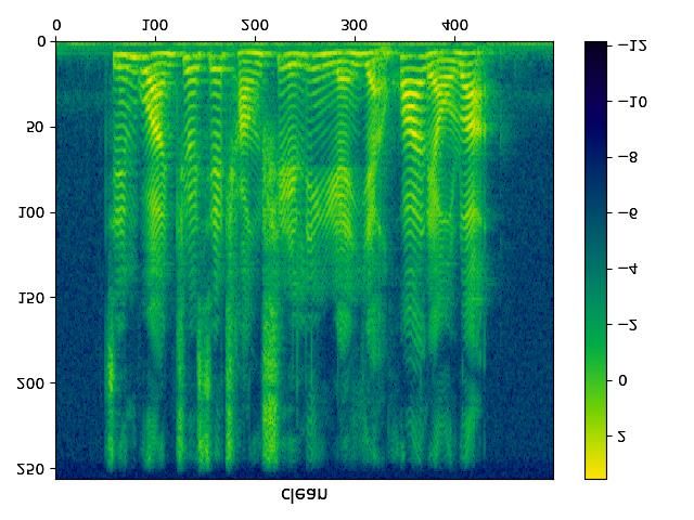
Harmonic locations prediction Gated Harmonic Compensation Skip concatenate
Add
Noisy signal CausalConv
GCB
Coarse enhancement module
VAD
FCB RB VRD BatchNorm
Conv-stft Input
RVAD + RVRD Gate Cat Sigmoid PReLU
Encoder
Elemental Mul
FCA RA Gate
LSTM Mask Apply E
RH
FC Harmonic GCB GCB … GCB Mask Apply M
integral Mag/Phase
Decoder M/P
2 CA CB |S'| conversion
M/P Mag Mask
Mask S'phase S''
S' Conv-istft Result
Fig. 1. Architecture of the proposed HGCN.
tion [17]. So, the input to the encoder is the noisy complex of 3600 pitches in 60~420 Hz (normal pitch range of human)
spectrum, denoted as S = Cat(Sr , Si ) ∈ RT ×2F , where Sr are taken as candidates. Then the Eq. (2) is improved to
0
and Si represent the real and imaginary parts of the spectrum Qt = log |St | · U > (3)
respectively. And, we compress the input of the encoder with 1×4200
where Qt ∈ R denotes the pitch candidate signifi-
power exponent 0.23 as in [18]. The decoder predicts a com-
cances of the t-th frame and the first 600 dimensions are 0.
plex ratio mask M = Cat(Mr , Mi ) ∈ RT ×2F , where Mr
The candidate corresponding to the maximum value in Qt is
and Mi represent the real and imaginary parts of mask. We
selected as the pitch, and the corresponding harmonic loca-
use the mask applying scheme of DCCRN-E [3], which is
tions are used as the result RH ∈ RT ×F , where the harmonic
called Mask Apply E in Fig. 1,
0
locations are 1 and the non-harmonic locations are 0.
S = |S| Mm ej(Sphase +Mphase ) Pitch candidates
= (Sr2 + Si2 )0.5 ej[arctan(Si ,Sr )+arctan(Mi ,Mr )]
Mm
(1)
where denotes the element-wise multiplication operator.
| · | and
(·)phase represent the magnitude and phase. Mm =
tanh (Mr2 + Mi2 )0.5 is the magnitude mask. tanh {·} is
the activation function proposed in [19]. CA and CB in Fig. 1
are introduced in the next section. FFT bins
Fig. 2. High-resolution harmonic integral matrix U .
The pitch and then harmonic locations for each frame can
2.2. Harmonic locations prediction module
be predicted by Eq. (3), but in fact, there are no harmonics in
0 0 0
The enhanced result S is first decoupled into |S | and Sphase . non-speech and unvoiced frames, so we apply VAD and VRD
HM will predict the harmonic locations based on the |S |.
0 to filter RH (green and pinkish boxes in Fig. 4). In addition,
There are peaks at integer multiples of the pitch and val- the energy corresponding to the locations is low even if it’s
leys at half-integer multiples, which are the characteristics of harmonic (blue box in Fig. 4), which need to be filtered out.
harmonics in the magnitude spectrum. Therefore, the pitch Therefore, the final harmonic gate is calculated as follows,
candidates can be set first, and the numerical integral of the Gate = RVAD RVRD RA RH (4)
multiple positions can be taken as the significance of each where RVAD ∈ RT ×1 and RVRD ∈ RT ×1 denote the speech
candidate. The candidate with the highest significance is the activity frames and voiced frames respectively. RA ∈ RT ×F
pitch [9, 20]. So, the significance Q is calculated as, denotes the non-low energy locations of speech. RT ×1 will
sr/f be copied and expanded into RT ×F .
X 1 0 1 0
Qt,f = ( √ · log |St,kf | − √ log |St,(k− 1 )f |) (2) Both VAD and VRD can be judged based on energy, so
k=1
k k 2
we design a speech energy detector to predict two non-low
where sr is half of the audio sample rate. f is the pitch candi- speech energy locations spectra RA and RB with different en-
date. And k denotes the multiple of the pitch. ergy thresholds, where RA is designed to filter out the lower
For T-F models, 512 Fourier points are often used for au- energy locations of speech with a smaller threshold, and RB
dio with 16k sample rate. Since the frequency bandwidth is is used for VAD and VRD with a larger threshold, which pays
31.25 Hz, few pitch candidates can be selected. To solve this more attention to the locations with higher energy. Since the
problem, a high-resolution integral matrix U is designed as detector needs to be able to resist noise, we change the output
Algorithm 1 and Fig. 2, where [·] is a rounding operation. We channel number of the last CEM decoder to (2 + CA + CB ),
set the pitch candidates with a resolution of 0.1 Hz, and con- where 2 is the channel number of complex ratio mask for
vert the multiple frequencies to the fixed spectral bins. A total speech enhancement. CA and CB are the channels number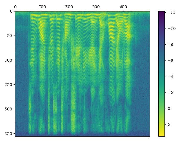
0
of the input X ∈ RT ×F ×CA/B for fully connected A (FCA )              Algorithm 1 Integral matrix
and B (FCB ) respectively. FCA and FCB output 2-D (low-                 1: U ← 0 ∈ R4200×F
high) classification probabilities Pt,f = [p0 , p1 ] for every T-F      2: for f ← 600 → 4200 do
point P ∈ RT ×F ×2 . And the category can be obtained by                3:     last_index ← 0
Rt,f = argmax(Pt,f ), then we can obtain the results of the             4:     for k ← 1 → [sr/(0.1 · f )] do
SED RA ∈ RT ×F and RB ∈ RT ×F .                                         5:         index ← [0.1 · f · k · F/sr] √
    The labels for the SED are shown in Fig. 3. We count the            6:         Uf,index ← Uf,index + (1/ k)
mean µ ∈ RF ×1 of each bin in the logarithmic magnitude                 7:         if index − last_index > 1 then
on the clean datas |S|˙ = [|Ṡ|1 , · · · , |Ṡ|d ] ∈ RD×T ×F , and      8:              i ← [(index − last_index)/2]
standard deviation σ ∈ RQ×1 of means,                                   9:              if (index − last_index) √   mod 2 6= 0 then
                                                                                             Uf,i ← Uf,i − 1/(2 k) √
                    D
                       " T                  ! #
                   X      X                                            10:
              µ=               log |Ṡ|i,t /T /D                (5)    11:                   Uf,i+1 ← Uf,i+1 − 1/(2 k)
                  t=1
            v i=1                                                      12:              else                     √
                                      #2
                                                                                             Uf,i ← Uf,i − 1/ k
            uD " T             !
            uX    X                                                    13:
         σ= t       log |Ṡ|i,t /T − µ /D                        (6)   14:         else
                       i=1   t=1
                                                                                                                      √
                                                                       15:              Uf,index ← Uf,index − 1/(2 k) √
where D represents the clip number of audio. |Ṡ| represents           16:              Uf,last_index ← Uf,last_index − 1/(2 k)
the magnitude spectra. The energy thresholds κ = (µ + ε ·
σ) ∈ RF ×1 of bins are controlled according to different offset
values ε (εA = 0 and εB = 34 ), and the label for RA/B is 1 if the     where CB1×1 is comprised of BN, CausalConv, and PReLU.
logarithmic magnitude of clean is larger than κ, 0 otherwise.          Secondly, GCL applies the α to the magnitude as X̃ = Xin
    Then we can compute RVAD and RVRD based on RB ,                    α, then fed X̃ into a convolutional layer. Finally, an RC fol-
                     (           PF
                            1 , f =1 (RB )t,f >                       lows the GCL and does a compensation process.
          (RVAD )t =             PF                            (7)         In GCBs, PReLU is used as the activation function, except
                            0 , f =1 (RB )t,f ≤
                                                                      for the last block which uses sigmoid to predict the compen-
                                  0 ,H > L                             sation magnitude mask MGHCM ∈ RT ×F . The magnitude
               (RVRD )t =                                      (8)
                                  1 ,H ≤ L                             mask applying is used and call it Mask Apply M,
              PF                            PF/2                                   00       0                  0         0
where H =        f =F/2 (RB )t,f and L =        f =1 (RB )t,f de-                S = (|S | + MGHCM           |S |)   ejSphase         (10)
note the number of selected speech points in high and low                                        00
                                                                          Finally, we convert S into waveform by iSTFT.
frequency respectively.  is the threshold for VAD.

                                                                                           3. EXPERIMENTS

                                                                       3.1. Dataset
                                                                       We evaluate the HGCN on the DNS Challenge (INTER-
           Clean               Label for RA       Label for RB
                                                                       SPEECH 2020) dataset [21]. This dataset includes 500 hours
Fig. 3. Labels for speech energy detection. RA is to filter out        of clean speech from 2150 speakers. The noise dataset in-
the lower energy locations with a smaller threshold, RB focus          cludes over 180 hours from 150 classes. For training, we
on the higher energy locations with a larger threshold.                generate 150 hours of noisy speech. The SNR is between
2.3. Gated harmonic compensation module                                0 dB and 40 dB. And data is divided into training and vali-
                                                                       dation set at 4 : 1. For testing, the SNR is between 0 dB and
A gated mechanism [12] is used to guide the model to com-              20 dB. And the speech data in the testing doesn’t participate
                               0
pensate for the coarse result S of CEM. The GHCM is com-               in the training or validation set, the noises are from [22]. A
posed of multiple gated compensation blocks (GCB) in series            total of 2 hours of test audio are generated.
to predict the magnitude compensation mask, where GCB is
composed of gated convolution layer (GCL) and residual con-
                                                    0
volution (RC). The input Xin of the first GCB is |S |, and the         3.2. Training setup and comparison methods
subsequent input is the output of the previous one.                    To ensure comparability, we train all models on our dataset
    The GCB introduce the gate mechanism during convolu-               with the same setup. The optimizer is Adam [23]. And the
tion. As shown in Fig. 1, we first obtain an attention map             initial learning rate is 0.001, which will decay 50% when
α ∈ RT ×F by concatenating gate Eq. (4) and the input fea-             the validation loss plateau for 5 epochs and the training is
ture in channel followed by CB1×1 ,                                    stopped if loss plateau for 20 epochs. The kernel size and
           α = sigmoid (CB1×1 (Cat(Gate, Xin )))                 (9)   stride are (5, 2) and (2, 1). DCRN is utilized as the baseline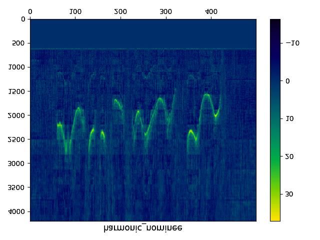
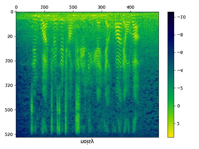
Input                 Q                  RH                                                  Gate             Clean
                                           Fig. 4. The calculation process of harmonic gate.
                          1
system. And DCCRN is an improved version of DCRN,                          GHCM is added on the top of CEM, and only RA is used
which ranked first in the Interspeech2020 DNS challenge               as the gate. Although the performance of the model is im-
real-time-track, so it’s utilized as the referenced system.           proved on all indexes, the improvement ratio of CEM+GHCM
    DCRN: The 32ms Hanning window with 25% overlap                    on PESQ is greater than that on SI-SDR, even in DNS2020
and 512-point STFT are used. The channel number of en-                test set, CEM+GHCM is higher than DCCRN on PESQ, but
coder and decoder is {16, 32, 64, 128, 128, 128}. And a 512-          it is lower on SI-SDR. This is due to that the GHCM com-
units FC layer after a 128-units LSTM is adopted.                     pensates for the magnitude and retains the phase of the coarse
    DCCRN: The 25ms Hanning window with 25% over-                     result. It further causes a slight mismatch between magni-
lap and 512-point STFT are used. The channel number is                tude and phase, while PESQ and STOI only care about the
{32, 64, 128, 256, 256, 256}, and uses two layers complex             magnitude, SI-SDR will be affected by both magnitude and
                                                                                                                                    00
LSTM with 128 units for real and imaginary parts respec-              phase. This is why we add SI-SNR to the loss function of S ,
tively. And a dense with 1280 units is after the LSTM. And            otherwise, the effect will be worse.
DCCRN looks ahead one frame in each decoder layer.                         HGCN (CEM+GHCM+HM) achieves the best results.
    HGCN(CEM+GHCM+HM): The parameter setting of                       We   visualize the calculation process of the harmonic gate as
CEM is the same as DCRN, except that the channel number               shown    in Fig. 4. We can observe that the HM can predict the
of last decoder is changed to 22 (CA = CB = 10). Three                exact   harmonic   locations, which can better guide the model
GCBs are adopted, and their channel numbers and stride are            to compensate     for the magnitude spectrum.
{8, 16, 8} and (1, 1). The  in Eq. (7) is set to 24. We designed          Real  Time  Factor   (RTF) is also tested on a machine with
                          0                          00
the loss functions for S and RA/B of CEM, S of GHCM,                  an  Intel(R)   Core(TM)    i5-6200U CPU@2.30 GHz in a sin-
                   0                                    00
separately. For S , we use APC-SNR [18]. For S , we use               gle  thread  (implemented    by ONNX). We can observe that the
scale-invariant SNR (SI-SNR) [24] and APC-SNR. For RA/B ,             proposed    model   brings better performance while maintaining
we use Focal loss [25].                                               good   speed.
         Table 1. System comparison on the test set.                  Table 2. System comparison on DNS-2020 synthetic test set.
    Model        RTF        PESQ STOI(%) SI-SDR(dB)                            Model         PESQ STOI(%) SI-SDR(dB)

   Noisy           -       1.796      93.2        10.321                    Noisy         1.582       91.5         9.071
   DCRN          0.061     2.798      96.3        18.096                    DCRN          2.615       95.7         17.275
   DCCRN         0.263     2.887      96.7        18.845                    DCCRN         2.711       96.0         17.967

   CEM           0.065     2.953      96.8        18.706                    CEM           2.753       96.1         17.539
   +GHCM         0.099     3.018      97.0        18.897                    +GHCM         2.812       96.3         17.841
     +HM         0.109     3.096      97.2        19.255                      +HM         2.883       96.5         18.144

                                                                                          4. CONCLUSION
3.3. Experimental results and discussion
We compare the performance of HGCN with comparison                   In this paper, to tackle the challenge of speech harmonics be-
methods on the test set, and three objective metrics are uti-        ing partially masked by noise, a harmonic gated compensa-
lized in the experiments, namely wide band PESQ (PESQ),              tion network for monaural speech enhancement is proposed.
STOI, and SI-SDR, as shown in Table 1. To ensure the gener-          First, we propose a high-resolution harmonic integral spec-
ality of the test set. We also did a test on DNS2020 synthetic       trum, which improves the accuracy of harmonic prediction
test set, shown in Table 2. Compared with DCRN, the per-             by increasing the resolution of the predicted pitch. In addi-
formance of the model has been gradually improved with the           tion, we design VAD and VRD to filter harmonic locations.
gradual addition of the CEM, GHCM, and HM modules.                   Finally, the harmonic gating mechanism is used to guide the
    The performance of CEM is improved compared to                   model to compensate for the coarse results from CRN to ob-
DCRN, which demonstrates the effectiveness of multi-task             tain the refinedly enhanced result. The experimental results
training [26], power compression, and loss function [18].            show that the high-resolution harmonic integral spectrum can
                                                                     predict the harmonic locations accurately, and the HGCN per-
  1 https://github.com/huyanxin/DeepComplexCRN                       forms better than referenced methods.
5. REFERENCES ate shift,” in Proc. of The 32nd International Conference
on Machine Learning, 2015, vol. 1, pp. 448–456.
[1] Y. Luo and N. Mesgarani, “Conv-tasnet: Surpass- [14] Wei J., Hu H., He Y., and Lu W., “Dilated causal convo-
ing ideal time–frequency magnitude masking for speech lution generative adversarial network end-to-end bone
separation,” IEEE/ACM Trans. Audio Speech Lang. conduction speech blind enhancement method,” 2019.
Proc., vol. 27, no. 8, pp. 1256–1266, 2019.
[15] K. He, X. Zhang, S. Ren, and J. Sun, “Delving deep
[2] K. Tan and D. Wang, “Complex spectral mapping with into rectifiers: Surpassing human-level performance on
a convolutional recurrent network for monaural speech imagenet classification,” in Proc. of ICCV, 2015, pp.
enhancement,” in Proc. of ICASSP. IEEE, 2019, pp. 1026–1034.
6865–6869.
[16] S. Hochreiter and J. Schmidhuber, “Long short-term
[3] Y. Hu, Y. Liu, S. Lv, M. Xing, S. Zhang, Y. Fu, J. Wu, memory,” Neural computation, vol. 9, no. 8, pp. 1735–
B. Zhang, and L. Xie, “Dccrn: Deep complex convolu- 1780, 1997.
tion recurrent network for phase-aware speech enhance-
[17] R. Gu, J. Wu, S. Zhang, L. Chen, Y. Xu, M. Yu, D. Su,
ment,” arXiv preprint arXiv:2008.00264, 2020.
Y. Zou, and D. Yu, “End-to-end multi-channel speech
[4] A. Li, C. Zheng, L. Zhang, and X. Li, “Glance separation,” arXiv preprint arXiv:1905.06286, 2019.
and gaze: A collaborative learning framework for [18] T. Wang and W. Zhu, “A deep learning loss function
single-channel speech enhancement,” arXiv preprint based on auditory power compression for speech en-
arXiv:2106.11789, 2021. hancement,” arXiv preprint arXiv:2108.11877, 2021.
[5] W. Jin, X. Liu, M. S Scordilis, and L. Han, “Speech en- [19] W. Malfliet and W. Hereman, “The tanh method: I. exact
hancement using harmonic emphasis and adaptive comb solutions of nonlinear evolution and wave equations,”
filtering,” IEEE transactions on audio, speech, and lan- Physica Scripta, vol. 54, no. 6, pp. 563, 1996.
guage processing, vol. 18, no. 2, pp. 356–368, 2009.
[20] M. R Schroeder, “Period histogram and product spec-
[6] D. Wang and J. Hansen, “Speech enhancement based on trum: New methods for fundamental-frequency mea-
harmonic estimation combined with mmse to improve surement,” The Journal of the Acoustical Society of
speech intelligibility for cochlear implant recipients.,” America, vol. 43, no. 4, pp. 829–834, 1968.
in INTERSPEECH, 2017, vol. 1, pp. 186–190.
[21] C. K. A. Reddy, E. Beyrami, H. Dubey, V. Gopal,
[7] D. Yin, C. Luo, Z. Xiong, and W. Zeng, “Phasen: R. Cheng, R. Cutler, S. Matusevych, R. Aichner,
A phase-and-harmonics-aware speech enhancement net- A. Aazami, S. Braun, P. Rana, S. Srinivasan, and
work,” in Proc. of the AAAI Conference on Artificial J. Gehrke, “The interspeech 2020 deep noise suppres-
Intelligence, 2020, vol. 34, pp. 9458–9465. sion challenge: Datasets, subjective speech quality and
[8] Y. Wakabayashi, T. Fukumori, M. Nakayama, testing framework,” arXiv preprint arXiv:2001.08662,
T. Nishiura, and Y. Yamashita, “Phase reconstruc- 2020.
tion method based on time-frequency domain harmonic [22] H. Hirsch and D. Pearce, “The aurora experimental
structure for speech enhancement,” in Proc. of ICASSP. framework for the performance evaluation of speech
IEEE, 2017, pp. 5560–5564. recognition systems under noisy conditions,” in
[9] A. Camacho, SWIPE: A sawtooth waveform inspired ASR2000-Automatic speech recognition: challenges for
pitch estimator for speech and music, University of the new Millenium ISCA tutorial and research workshop
Florida Gainesville, 2007. (ITRW), 2000.
[10] M. Une and R. Miyazaki, “Musical-noise-free speech [23] D. P. Kingma and J. L. Ba, “Adam: A method for
enhancement with low speech distortion by biased har- stochastic optimization,” in ICLR 2015 : International
monic regeneration technique,” in Proc. of IWAENC. Conference on Learning Representations 2015, 2015.
IEEE, 2018, pp. 31–35. [24] J. L. Roux, S. Wisdom, H. Erdogan, and J. R Hershey,
[11] Z. Ouyang, H. Yu, W. Zhu, and B. Champagne, “A “Sdr–half-baked or well done?,” in Proc. of ICASSP.
deep neural network based harmonic noise model for IEEE, 2019, pp. 626–630.
speech enhancement.,” in INTERSPEECH, 2018, pp. [25] T. Lin, P. Goyal, R. Girshick, K. He, and P. Dollár, “Fo-
3224–3228. cal loss for dense object detection,” in Proc. of the IEEE
international conference on computer vision, 2017, pp.
[12] J. Yu, Z. Lin, J. Yang, X. Shen, X. Lu, and T. Huang,
2980–2988.
“Free-form image inpainting with gated convolution,” in
Proc. of ICCV, 2019, pp. 4470–4479. [26] S. Lv, Y. Hu, S. Zhang, and L. Xie, “Dccrn+: Channel-
wise subband dccrn with snr estimation for speech en-
[13] S. Ioffe and C. Szegedy, “Batch normalization: Acceler-
hancement,” arXiv preprint arXiv:2106.08672, 2021.
ating deep network training by reducing internal covari-You can also read