HGW 1033-32 Wireless Handheld Operating Panel - Technical Manual - Sigmatek
←
→
Page content transcription
If your browser does not render page correctly, please read the page content below

HGW 1033-32
   Wireless Handheld Operating
              Panel

                               Technical Manual

Date of creation: 16.01.2019     Version date: 05.03.2020   Article number: 12-246-1033-32E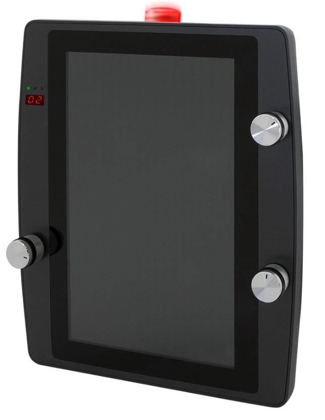
Publisher: SIGMATEK GmbH & Co KG
                                   A-5112 Lamprechtshausen
                                      Tel.: +43/6274/4321
                                    Fax: +43/6274/4321-18
                                   Email: office@sigmatek.at
                               WWW.SIGMATEK-AUTOMATION.COM

                                               Copyright © 2019
                                            SIGMATEK GmbH & Co KG

                                      Translation from German

All rights reserved. No part of this work may be reproduced, edited using an electronic system, duplicated or dis-
tributed in any form (print, photocopy, microfilm or in any other process) without the express permission.

We reserve the right to make changes in the content without notice. SIGMATEK GmbH & Co KG is not responsible for
technical or printing errors in the handbook and assumes no responsibility for damages that occur through use of
this handbook.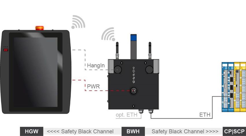
10.1” WIRELESS HANDHELD OPERATING PANEL                HGW 1033-32

10.1” Wireless Handheld Operating Panel HGW 1033-32
In combination with a BWH 001 base station and a safety-related PLC, the HGW 1033-32 is
a wireless, intelligent manual operating unit with emergency stop function that enables the
programming, visualization and diagnosis of processes and systems control.

Process data, procedures and parameters are comfortably presented on the 10.1” display
and can be entered or changed via the touch screen.

The HGW 1033-32 can be coupled with machines via base stations, which allows the flexible
application of the operating unit.

The interfaces can be used to configure the terminal. The integrated battery pack enables 2
hours of operation at full capacity.

Additionally, three rotary encoders are integrated into the front of the HGW 1033-32.

05.03.2020                                                                              Page 1
HGW 1033-32      10.1” WIRELESS HANDHELD OPERATING PANEL

Contents
1    Introduction ............................................................................. 7
     1.1         Target Group/Purpose of this Manual ........................................ 7

     1.2         Important Reference Documentation ......................................... 7

     1.3         Contents of Delivery ..................................................................... 7

2    Basic Safety Guidelines ......................................................... 8
     2.1         Symbols Used ............................................................................... 8

     2.2         Disclaimer ...................................................................................... 9

     2.3         General Safety Guidelines ......................................................... 10

     2.4         Designated Use ........................................................................... 11

     2.5         Software/Training ....................................................................... 14

3    Residual Risks .......................................................................15
     3.1         Safety of the Machine or Equipment ........................................ 15

     3.2         Regular Technical Inspection of the Emergency Stop ........... 16

     3.3         Guidelines.................................................................................... 17
         3.3.1        Functional Safety Standards.............................................................. 17

         3.3.2        EU Conformity Declaration ................................................................ 17

     3.4         Safety-Relevant Parameters ...................................................... 18

     3.5         Wireless System Operation ....................................................... 18

4    Technical Data .......................................................................19
     4.1         Performance Data ....................................................................... 19

     4.2         Electrical Requirements ............................................................. 20

Page 2                                                                                               05.03.2020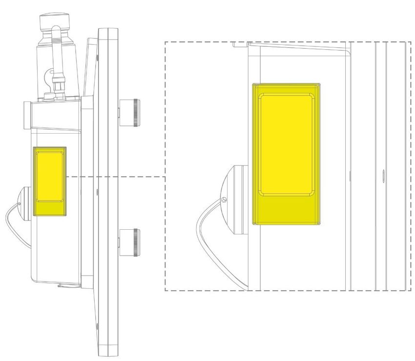
10.1” WIRELESS HANDHELD OPERATING PANEL                                           HGW 1033-32

      4.3        Display ......................................................................................... 21

      4.4        Input ............................................................................................. 21

      4.5        Environmental Conditions ......................................................... 22

      4.6        Wireless ....................................................................................... 23
        4.6.1         WLAN 2.4 GHz ................................................................................. 23

        4.6.2         WLAN 5 GHz .................................................................................... 23

        4.6.3         Antennae........................................................................................... 23

      4.7        Miscellaneous ............................................................................. 24

5    Mechanical Dimensions ........................................................ 25
      5.1        HGW ............................................................................................. 25

      5.2        HGW with BWH ........................................................................... 26

6    Interfaces ............................................................................... 27
      6.1        Connections Bottom................................................................... 27
        6.1.1         X1: USB 2.0 (Type A) ....................................................................... 27

        6.1.2         X2: USB 2.0 DualRole (Type C)........................................................ 28

      6.2        Rear Connectors ......................................................................... 29
        6.2.1         X15: Power/Data ............................................................................... 29

      6.3        Display ......................................................................................... 31
        6.3.1         Underside.......................................................................................... 31

        6.3.2         Front ................................................................................................. 32

      6.4        WLAN ........................................................................................... 34

      6.5        Acoustics ..................................................................................... 36

      6.6        On/Off Button (illuminated) ........................................................ 37

      6.7        Key Switch ................................................................................... 38
05.03.2020                                                                                                           Page 3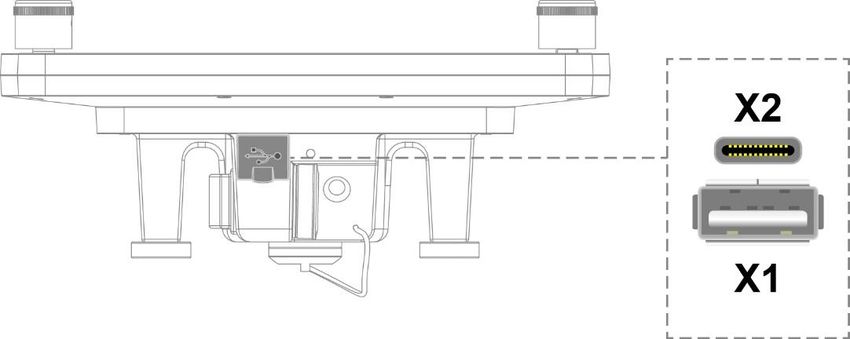
HGW 1033-32       10.1” WIRELESS HANDHELD OPERATING PANEL

     6.8          Confirmation Switch ................................................................... 39

     6.9          Emergency Stop (illuminated) ................................................... 40

     6.10         Rotary Encoder ........................................................................... 41

7    Status and Error Messages...................................................42

8    Transport & Storage ..............................................................50

9    Assembly & Installation ........................................................51
     9.1          Check List .................................................................................... 51
         9.1.1         Check Contents of Delivery ............................................................... 51

     9.2          Preparing the Hardware ............................................................. 51

10   Operation & Start-up..............................................................52
     10.1         Battery & Power Supply ............................................................. 53

     10.2         Configuration .............................................................................. 54

     10.3         Testing the Operating Area........................................................ 55

     10.4         Operation ..................................................................................... 56
         10.4.1        General .............................................................................................. 56

         10.4.2        Turning On......................................................................................... 58

         10.4.3        Coupling ............................................................................................ 58

         10.4.4        Non-Safety Mode............................................................................... 60

         10.4.5        Decoupling......................................................................................... 61

         10.4.6        Safety Functions ................................................................................ 62

         10.4.7        Turning Off......................................................................................... 63

         10.4.8        Evaluating Operating Elements ......................................................... 63

Page 4                                                                                                         05.03.2020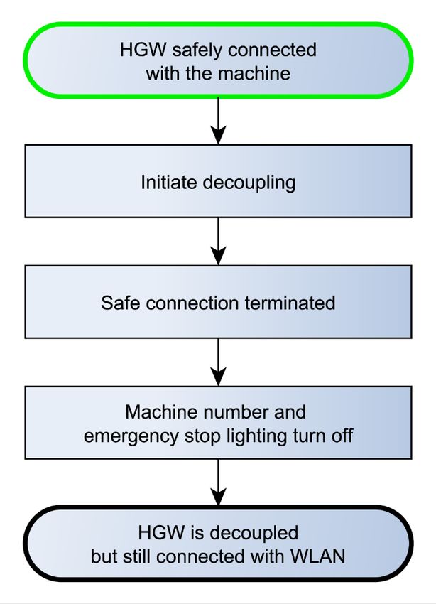
10.1” WIRELESS HANDHELD OPERATING PANEL                                        HGW 1033-32

11   Storage ................................................................................... 64

12   Help with Disruptions/Troubleshooting .............................. 65

13   Maintenance........................................................................... 66
      13.1       Cleaning the Touch Screen ....................................................... 66

      13.2       Maintenance ................................................................................ 67
        13.2.1        Calibrating the Touch Screen............................................................ 67

      13.3       Repair ........................................................................................... 67

14   Disposal ................................................................................. 68

15   Accessories ........................................................................... 69
      15.1       Antennae ...................................................................................... 69

      15.2       Touch Pen .................................................................................... 69

      15.3       Edge Protection .......................................................................... 69

16   Application Information ........................................................ 70
      16.1       Application Example .................................................................. 70
        16.1.1        Visualization Example ....................................................................... 71

      16.2       Configuring Safety Components............................................... 72
        16.2.1        Minimum System Requirements ....................................................... 72

        16.2.2        Adding the HGW 1033-32 to a Safety Designer Project ................... 73

        16.2.3        “SF_HGW_Login” Function Block ..................................................... 73

        16.2.4        Key Switch ........................................................................................ 73

        16.2.5        Confirmation Switch .......................................................................... 73

        16.2.6        Emergency Stop ............................................................................... 74

05.03.2020                                                                                                       Page 5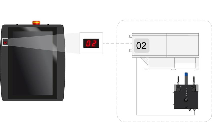
HGW 1033-32   10.1” WIRELESS HANDHELD OPERATING PANEL

     16.3     HW Facts...................................................................................... 75

     16.4     Updates ........................................................................................ 75

Page 6                                                                                            05.03.2020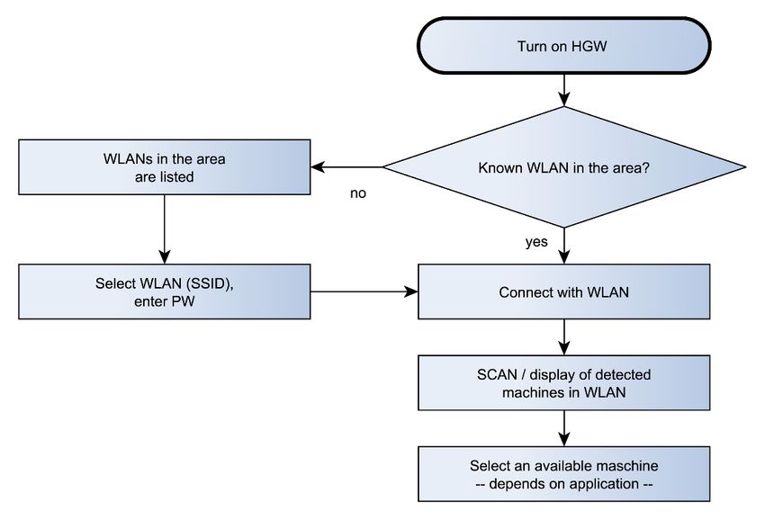
10.1” WIRELESS HANDHELD OPERATING PANEL               HGW 1033-32

1     Introduction
1.1       Target Group/Purpose of this Manual
This manual contains all information required for the safety-related operation of the
HGW 1033-32.

This manual is intended for:

      •    Project planners
      •    Technicians
      •    Commissioning engineers
      •    Machine operators
      •    Maintenance/test technicians

General knowledge of automation technology in safety-related systems is required.

Further help and information on training and the appropriate accessories can be found on our
website www.sigmatek-automation.com

Our support team is happily available to answer your questions.
Please see our website for our hotline number and business hours.

1.2       Important Reference Documentation

      •    Safety System Handbook
      •    HGW 1033-X_Maintanance Manual
      •    HGW_BWH_Configuration Manual
      •    WLAN Configuration

These documents can be downloaded from our website or obtained through Support.

1.3       Contents of Delivery
1x HGW 1033-32
2x keys

This document can be downloaded from our website.
Additional documents may be included with delivery.

05.03.2020                                                                          Page 7
HGW 1033-32 10.1” WIRELESS HANDHELD OPERATING PANEL
2 Basic Safety Guidelines
2.1 Symbols Used
The following symbols are used in the user documentation for warning and danger messages,
as well as informational notes:
DANGER Identifies an immediate danger with high risk, which will lead to immediate
death or serious injury if not avoided.
Identifie un danger immédiat avec un risque élevé, entraînant le décès im-
médiat ou des blessures graves s’il n’est pas évité.
WARNING Identifies a possible danger with a mid-level risk, which can lead to death or
(serious) injury if not avoided.
Indique un danger possible d’un risque moyen de décès ou de (graves)
blessures si les consignes de sécurité ne sont pas respectées
CAUTION Identifies a low risk danger, which can lead to injury or property damage if
not avoided.
Indique un danger avec un niveau de risque faible des blessures légères ou
des dommages matériels si les consignes de sécurité ne sont pas re-
spectées.
Warning, dangerous electrical voltage.
Attention, tension électrique dangereuse.
Provides user tips, informs of special features and identifies especially im-
portant information in the text.
Fournit des conseils d’utilisation, informe sur les fonctions particulaires et
souligne les informations particulièrement importantes dans le texte.
Danger for ESD-sensitive components.
Les signes de danger pour les composants sensibles aux décharges élec-
trostatiques.
Page 8 05.03.202010.1” WIRELESS HANDHELD OPERATING PANEL HGW 1033-32
2.2 Disclaimer
The contents of this document were prepared with the greatest care. How-
ever, deviations cannot be ruled out. This document is regularly checked and
required corrections are included in the subsequent versions. The machine
manufacturer is responsible for the proper assembly, as well as device con-
figuration. The machine operator is responsible for safe handling, as well as
proper operation.
The current document can be found on our website. If necessary, contact our
support.
Subject to technical changes, which improve the performance of the devices.
The following documentation represents a series of product descriptions. It
does not guarantee properties under the warranty.
Please thoroughly read the corresponding data sheets, operating instructions
and this system handbook before handling a product.
SIGMATEK GmbH & Co KG is not liable for damages caused through
non-compliance with these instructions or applicable regulations.
The general and special safety instructions described in the following sec-
tions, as well as technical regulations, must therefore be observed.
05.03.2020 Page 9HGW 1033-32 10.1” WIRELESS HANDHELD OPERATING PANEL
2.3 General Safety Guidelines
According to EU Guidelines, the operating instructions are a component of a
product.
This manual must therefore be accessible in the vicinity of the machine since
it contains important instructions.
This technical documentation should be included in the sale, rental or transfer
of the product, or its online availability indicated.
Maintain this manual in readable condition and keep it accessible for refer-
ence.
This device contains a Li-Ion battery. For this reason, we refer you to the
manufacturer’s specification (battery safety data sheet). This can be found
on our website.
Regarding the requirements for Safety and health connected to the use of
machines, the manufacturer must perform a risk assessment in accordance
with machine guidelines 2006/42/EG before introducing a machine to the
market.
Before commissioning this product, check that conformance with the provi-
sions of the 2006/42/EG guidelines is correct. As long as the machine, with
which the with the HGW or BWH should be used does not comply with the
guideline, operating this product is prohibited.
Operate the unit with devices and accessories approved by SIGMATEK only.
CAUTION Handle the device with care and do not drop or let fall.
Prevent foreign bodies and fluids from entering the device.
The device must not be opened, otherwise it could be damaged!
Manipulez l’appareil avec précaution et ne le laissez pas tomber.
Empêchez les corps étrangers et les liquides de pénétrer dans l’appareil.
L’appareil ne doit pas être ouvert, sinon il risque d’être endommagé!
Regularly check the housing for mechanical damage.
Vérifier régulièrement l’absence de dommages mécaniques sur le boîtier.
Page 10 05.03.202010.1” WIRELESS HANDHELD OPERATING PANEL HGW 1033-32
2.4 Designated Use
The Safety functions implemented in the Safety modules are designed for use with safety-
related applications in a PLC control and meet the required conditions for safe operation in
SIL 3 or SIL CL 3 according to EN 62061 and in compliance with PL e. Cat. 4 in accordance
with EN ISO 13849-1.
CAUTION The instructions contained in this document must be followed.
For error-free operation, proper transport and storage are essential. See
chapter 8 for more information.
Installation, mounting, programming, initial start-up, operation, maintenance
and decommissioning can only be performed by qualified personnel.
Qualified personnel in this context are people who have completed training
or have trained under supervision of qualified personnel and have been au-
thorized to operate and maintain safety-related equipment, systems and fa-
cilities in compliance with the strict guidelines and standards of safety tech-
nology. The applicable environmental conditions must be maintained.
Les instructions contenues dans ce document doivent être suivies.
Pour un fonctionnement sans erreur, le transport et le stockage appropriés
sont essentiels. Voir le chapitre 8 pour plus d’informations.
L’installation, le montage, la programmation, la mise en service initiale, l’ex-
ploitation, la maintenance et la mise hors service ne peuvent être effectués
que par une personne qualifiée.
Dans ce contexte, on entend par personnel qualifié les personnes qui ont
suivi une formation ou qui ont été formées sous la supervision d’un personnel
qualifié et qui ont été autorisées à utiliser et à entretenir l’équipement, les
systèmes et les installations de sécurité conformément aux directives et aux
normes strictes de la technique de sécurité. Les conditions environnemen-
tales applicables doivent être respectées.
For your own safety and that of others, the safety modules should be used
for their designated purpose only.
Correct EMC installation is also included in the designated use.
Pour votre propre sécurité et celle des autres, les modules de sécurité ne
doivent être utilisés qu’à des fins prévues.
Une installation CEM correcte est également incluse dans l’utilisation prévue.
05.03.2020 Page 11HGW 1033-32 10.1” WIRELESS HANDHELD OPERATING PANEL
Non-designated use consists of:
• any changes made to the module or the use of damaged modules.
• use of the module inconsistent with the technical margins de-
scribed in this manual or the speciation's defined in the technical
data (see chapter 4).
L'utilisation non désignée consiste en:
• toute modification apportée au module ou l'utilisation des modules
endommagés.
• utilisation du module non conforme aux marges techniques dé-
crites dans ce manuel ou aux spécifications définies dans les don-
nées techniques (voir chapitre 4).
Page 12 05.03.202010.1” WIRELESS HANDHELD OPERATING PANEL HGW 1033-32
CAUTION In addition, the Safety Guidelines in the other sections of these instructions
must be observed. These instructions are visually emphasized by symbols.
The module complies with EN 61131-2.
In combination with a machine, the machine builder must comply with EN
60204-1 standards.
For your own safety and that of others, compliance with the environmental
conditions is essential.
The control cabinet must be connected to ground correctly.
To perform maintenance or repairs, disconnect the system from the power
supply.
As required by EN ISO 13850, section 4.1 and EN 60204-1, section 10.7.1,
confusion between a functioning and non-functioning handheld control panel
is possible must be prevented.
Before delivering the module, the machine manufacturer must ensure that it
is in “delivery condition”. See chapter 8 for more information.
If an operating panel is not coupled and not in use, keep it in a location with
restricted access.
En outre, les consignes de sécurité mentionnées dans d’autres sections de
ce manuel doivent être respectées. Ces directives sont indiquées avec les
symboles graphiques.
Le module est conforme à la norme EN 61131-2.
En combinaison avec une machine, le constructeur de la machine doit re-
specter la norme EN 60204-1.
L’armoire de commande doit être raccordée correctement à la terre.
Pour l'entretien et les réparations, débranchez le système de l'alimentation.
Conformément à la norme EN ISO 13850, section 4.1 et EN 60204-1, section
10.7.1, la confusion entre un panneau de commande portatif fonctionnel et
non fonctionnel doit être évitée.
Avant de livrer le module, le constructeur de la machine doit s'assurer qu'il
est en "état de livraison". Voir le chapitre 8 pour plus d'informations.
Si un panneau de commande n'est pas couplé et n'est pas utilisé, conservez-
le dans un endroit à accès restreint.
05.03.2020 Page 13HGW 1033-32 10.1” WIRELESS HANDHELD OPERATING PANEL
Hardware and software features (application-specific data) can be found in
chapter 16
Application Information.
2.5 Software/Training
The application is created with the software LASAL Class 2 and LASAL Screen Editor; the
Safety application is created using the Safety Designer. Basic information on safety can be
found in the Safety System Handbook.
Training for the LASAL development environment, with which the HGW can be configured, is
provided. Information on our training schedule is available on our website.
Page 14 05.03.202010.1” WIRELESS HANDHELD OPERATING PANEL HGW 1033-32
3 Residual Risks
CAUTION According to the EU guideline 2006/42/EG (machine guideline), the machine
manufacturer must perform a risk assessment, which includes the possible
residual risks posed by the product. These include:
• unwanted movements of driven machine components
• unwanted temperatures, emissions of gas, particles, smell and light.
• dangerous contact voltages
• the effects of electrical, magnetic and electromagnetic fields pro-
duced during operation (for example, on pacemakers and implants)
• possible effects of information technology devices (cell/smart
phones etc.)
• release of non-environmentally compatible substances and emis-
sions
Conformément à la directive européenne 2006/42/CE (directive machines),
le fabricant de la machine doit procéder à une évaluation des risques, y com-
pris les risques résiduels éventuels présentés par le produit. Il s'agit notam-
ment de:
• Mouvements involontaires des pièces entraînées de la machine.
• Températures non désirées, les émissions de gaz, les particules,
l'odeur et la lumière.
• Tensions de contact dangereuses
• Les effets des champs électriques, magnétiques et électro-
magnétiques produites pendant le fonctionnement (par exemple,
sur les stimulateurs cardiaques et les implants).
• Les effets possibles sur les dispositifs de technologie de l'infor-
mation (téléphones cellulaires / téléphones intelligents, etc.)
• Dégagement de substances et d'émissions non respectueuses de
l'environnement.
3.1 Safety of the Machine or Equipment
Strict compliance with the safety guidelines is required, otherwise all warranties and claims
are invalid:
Observe all on-site rules and regulations for accident prevention and occu-
pational safety.
05.03.2020 Page 15HGW 1033-32 10.1” WIRELESS HANDHELD OPERATING PANEL
3.2 Regular Technical Inspection of the Emergency Stop
CAUTION The emergency stop illumination must be regularly checked for clear recog-
nition. The lighting must also be clearly recognizable under adverse condi-
tions (e.g. effects of sunlight or clouding of the plastic).If this is no longer
ensured, the emergency stop must be exchanged. To exchange the emer-
gency stop, the device must be sent to SIGMATEK.
L'éclairage d'arrêt d'urgence doit être vérifié régulièrement pour une recon-
naissance claire. L'éclairage doit également être clairement reconnaissable
dans des conditions défavorables (p. ex. effets de la lumière du soleil ou de
l'obscurcissement du plastique).Si l'éclairage n'est plus fonctionnel, l'arrêt
d'urgence doit être remplacé. L'appareil doit être envoyé à SIGMATEK pour
un échange de l'arrêt d'urgence.
The emergency stop should be regularly checked for manipulation and dam-
age.
L'arrêt d'urgence doit être vérifié régulièrement pour vérifier qu'il n’a pas subi
de manipulations ou de dommages.
The HGW 1033-32 has a defined internal testing interval of 30 days for the mechanical input
and optical elements (emergency stop incl. illumination, confirmation switch and 7-segment
display). The user is prompted by the system to perform a test before coupling to a machine,
operation can only continue after the test was run successfully. The test interval can be man-
ually shortened or initialized via the application. If this does not happen, the internal check
interval is triggered every 30 days at the latest.
Page 16 05.03.202010.1” WIRELESS HANDHELD OPERATING PANEL HGW 1033-32
3.3 Guidelines
The device was constructed in compliance with the following European Union guidelines.
3.3.1 Functional Safety Standards
EN 62061 SIL 3 or SIL CL 3
EN ISO 13849-1/-2 PL e / CAT 4
EN ISO 13850
3.3.2 EU Conformity Declaration
CE Declaration of Conformity
The HGW 1033-32 conforms to the following European guidelines:
• 2006/42/EG “Directive of the European Parliament and of the Coun-
cil of 17 May 2006 on Machinery and Change to the Directive
95/16/EC” (machine guideline)
• 2014/30/EU “Electromagnetic Compatibility” (EMC guideline)
• 2014/53/EU “Directive of the European Parliament and of the Coun-
cil of 16 April 2014 on the harmonization of the laws of the Member
States relating to the provision of wireless equipment on the market
and repealing Directive 1999/5/EC” (wireless device guideline)
• 2011/65/EU Restricted use of certain hazardous substances in
electrical and electronic equipment (RoHS Guideline)
The EU Conformity Declarations are provided on the SIGMATEK website.
See Products/Downloads or use the search function and keywork EU Decla-
ration of Conformity.
05.03.2020 Page 17HGW 1033-32 10.1” WIRELESS HANDHELD OPERATING PANEL
3.4 Safety-Relevant Parameters
The use of the specified parameters requires a risk analysis of the end application.
Input Module Safety Parameters(*)
HGW 1033-32 PFHD = 2.64E-09 (1/h)
MTTFd = 766 years
DC = 99.24 %
SFF = 99,81 %
Confirmation switch B10D = 100,000
Emergency stop switch B10D = 250,000
Key switch B10D = 10,000
Transmission route (WLAN) PFHD 1.71E-10
between the HGW 1033-32 and
Safe CPU. Worst-Case Calcu-
lation
(*) Depending on the application, the probability of failure must be determined for the elec-
tromechanical components included based on the B 10D values listed here and integrated into
the calculation for the entire system. The Safe CPU SCP 111 must also be calculated in.
3.5 Wireless System Operation
CAUTION Technical changes to the device (such as different antennae), as well as im-
proper use can lead to the loss of the FCC license and generate interference,
which can affect the function of nearby devices.
Please note the national standardization when operating the wireless device!
Les changements techniques apportés à l'appareil (comme les différentes
antennes), ainsi qu'une utilisation incorrecte peuvent entraîner la perte de la
licence FCC et générer des interférences, ce qui peut affecter le fonctionne-
ment des appareils voisins.
Lors de l'utilisation de l'appareil sans fil, veuillez respecter les normes natio-
nales en vigueur!
Page 18 05.03.202010.1” WIRELESS HANDHELD OPERATING PANEL HGW 1033-32
4 Technical Data
4.1 Performance Data
Processor EDGE2 Technology
Processor cores 2
Internal cache 32-kbyte L1 Instruction Cache
32-kbyte L1 Data Cache
512-Kbyte L2 Cache
Internal program and 2048-Mbyte
data memory (DDR3 RAM)
Internal remnant 512-kbyte MRAM
data memory
Internal storage device 512-Mbyte microSD card, expandable*
Internal I/O no
Battery 3780 mAh (minimum) Lithium-Ion
Runtime: > 2 h continuous operation with new battery
Charge/status display via the on/off button
Charging time 3 h via USB-C as well as base station at 25 °C
with a rising temperature and active use of the device, the charge time may
increase
Interfaces 1x USB 2.0 Type-A (Host)
1x USB 2.0 Type-C (Dual Role Port
charge: USB-PD Profile 4: 20 V, 3 A, 60 W)
1x WLAN dual-band (2.4 GHz, 5 GHz simultaneously)
Internal interface connections and 1x TFT color display
devices
1x USB (touch connection)
Control Elements Touch screen (multi-touch, projective capacitive)
1x confirmation switch (2 normally open, 3-stage)
1x key switch (2 normally open)
1x illuminated emergency stop switch (2 normally closed)
1x illuminated on/off button (with application interface)
3x rotary encoder (analyzable via the application)
Display 10.1” TFT color display, 16:10, portrait mode
Resolution WXGA 800 x 1280 pixels
05.03.2020 Page 19HGW 1033-32 10.1” WIRELESS HANDHELD OPERATING PANEL
Status LEDs 3x front (controllable via application)
1x rear (boot status/controllable via the application)
1x normally open gate (shows power and charge status)
Signal generator yes (at least 83 dB at 30 cm)
Real-time clock yes (buffered circa 3 days via internal battery)
Temperature sensors 4 (2x LP, 1x CPU, 1x battery)
Cooling passive (fanless)
Coupling display 7-segment LED, two-digit
Input voltage measurement yes
(*) For safety reasons, the device may only be expanded by trained personnel.
4.2 Electrical Requirements
Charging voltage typically +19 V DC
magnetic connector
minimum +15 V DC maximum +24 V
Charging current via base station: up to 2.5 A at 15.5 V
USB Host current load maximum 0.5 A
The specified charging time relates to the charging process when the panel
is not simultaneously in. If the device is in use while charging, the charging
time may be extended.
To protect the battery, the intelligent charging circuit monitors the ambient
temperature. For this reason, the charging time can increase at high ambient
temperatures.
The specified current consumption relates to the status without connected
peripherals (USB stick ...)
Page 20 05.03.202010.1” WIRELESS HANDHELD OPERATING PANEL HGW 1033-32 4.3 Display Type 10.1” TFT LCD color display Active range 135.6 (V) x 216.96 (H) mm Resolution WXGA 800 x 1280 pixels Color depth 18-bit RGB (16.7 million colors) LCD mode normal black LCD Polarizer transmissive Pixel size 0.1695 x 0.1695 mm Backlighting LED, adjustable Contrast typically 800 : 1 Brightness typically 300 cd/m² Angle CR ≥ 10 85° from all sides 4.4 Input Input Multi-touch screen (PCAP) Emergency stop switch 1 Confirmation switch 1 (3 switch positions with panic function) Key switch 1 (2 switch positions) On/off button 1 Rotary encoder 3 05.03.2020 Page 21
HGW 1033-32              10.1” WIRELESS HANDHELD OPERATING PANEL

4.5     Environmental Conditions

  Storage temperature                                   -5 … +60 °C (in transport mode)

  Environmental temperature dis-                                   0 ... +50 °C
  charging

  Environmental temperature charg-                                 0 ... +40 °C
  ing

  Humidity                                                 10-95 %, non-condensing

  Installation altitude above sea                          0-2000 m without derating
  level
                                     > 2000 m up to a maximum of 5000 m with derating of the maximum envi-
                                                   ronmental temperature by 0.5 °C per 100 m

  Operating conditions                                          pollution degree 2

  EMC resistance                            EN 61000-6-2:2007 (industrial area); EN 61000-6-7:2015
                                                     (immunity industrial functional safety)
                                             (increased requirements according to IEC/EN 62061)

  EMC noise generation                                           EN 61000-6-4

  Shock resistance                            EN 60068-2-27                             150 m/s²

  Vibration resistance                                               10 m/s²

  Protection type                               EN 60529                                  IP54
                                                                                  (with USB cover only)

  Free fall                                 DIN EN 60068-2-31                          1000 mm
  (rough handling)

  Free fall                                  IEC 60068-2-32                            1000 mm
  (with packaging)

                     The HGW has an intelligent charging circuit, which ensures optimal charging
                     of the integrated battery pack. For this reason, the HGW can remain docked
                     to the base station.
                     The HGW is delivered with a partially charged battery and should be com-
                     pletely charged by the customer before use.
                     With a 30 % charge, the device can be stored in transport mode for 6 months
                     at 25 °C.
                     After 6 months, the battery must be recharged to avoid damage to the bat-
                     tery.

Page 22                                                                                            05.03.2020
10.1” WIRELESS HANDHELD OPERATING PANEL HGW 1033-32
4.6 Wireless
4.6.1 WLAN 2.4 GHz
Frequency range 2399.5-2484.5 MHz
Transmission power max. 20 dBm (100 mW) EIRP
Channels 1-14 (2412-2483.5 MHz)
4.6.2 WLAN 5 GHz
Frequency range 5150-5350 MHz
5470-5725 MHz
Transmission power max. 23 dBm (200 mW) EIRP
Channels 36-64 (5180-5320 MHz)
100-140 (5500-5700 MHz)
4.6.3 Antennae
Number 2
Frequency range 2.4/5 GHz (Dual-Band)
Transmission power max. 25 W
Antenna gain 2.4 GHz-4 dBi Peak Gain
5 GHz-5.2 dBi Peak Gain
Impedance 50 Ω
Transmission angle/characteristic Transmission characteristic: omnidirectional
Polarization: linear
The panels can only be used in the country designated or configured for this
purpose, as the maximum permitted transmission power, as well as approved
channels can greatly differ.
Non-compliance with these specifications can result in legal consequences,
for which SIGMATEK accepts no liability!
Already during the planning stage, caution must be taken to ensure that the
radio channels are configured so that interference with other products is pre-
vented.
05.03.2020 Page 23HGW 1033-32 10.1” WIRELESS HANDHELD OPERATING PANEL
CAUTION Only antennae approved by SIGMATEK can be used. See chapter 15.1.
Seules les antennes recommandées par SIGMATEK peuvent être utilisées.
Voir chapitre 15.1.
Regularly check the screw fitting for the antennae. If necessary, manually
tighten them or use a torque wrench (1 Nm) for SMA connectors.
Vérifiez régulièrement le vissage des antennes. Si nécessaire, serrez-les ma-
nuellement ou utilisez une clé dynamométrique (1 Nm) pour les connecteurs
SMA.
4.7 Miscellaneous
Article number 12-246-1033-32
Hardware version 1.x
Operating System Salamander
Approvals CE, TÜV-Austria EG-type-examined
Page 24 05.03.202010.1” WIRELESS HANDHELD OPERATING PANEL HGW 1033-32
5 Mechanical Dimensions
5.1 HGW
Dimensions 226 x 276 x 96 mm (W x H x D)
Material housing: PC/ASA
color: RAL7024
Weight 1.39 kg
05.03.2020 Page 25HGW 1033-32 10.1” WIRELESS HANDHELD OPERATING PANEL 5.2 HGW with BWH Dimensions 226 x 313 x 125 mm (W x H x D) Weight 2,89 kg Page 26 05.03.2020
10.1” WIRELESS HANDHELD OPERATING PANEL               HGW 1033-32

6       Interfaces
6.1      Connections Bottom

6.1.1     X1: USB 2.0 (Type A)

                                                  Pin                      Function
                                                   1                +5 V, Iout,max = 500 mA
                                                   2                            D-
                                                   3                           D+
                                                   4                          GND

The Type-A interface can be used to connect various USB devices (keyboard, mouse, stor-
age media, hubs, etc.).

This interface can be used with a boot stick.

               Connected external devices (USB sticks or similar devices) can reduce the
               battery life.

    CAUTION    Do not use the HGW to charge mobile phones or other devices. The close
               proximity of these devices to the HGW can disrupt the wireless connection,
               as well as the function of the handheld operating panel.
               N'utilisez pas la HGW pour charger des téléphones portables ou d'autres
               appareils. La proximité de ces appareils par rapport au HGW peut perturber
               la connexion sans fil ainsi que le fonctionnement du panneau de commande
               portatif.

05.03.2020                                                                           Page 27
HGW 1033-32 10.1” WIRELESS HANDHELD OPERATING PANEL
6.1.2 X2: USB 2.0 DualRole (Type C)
Pin Function
A1, B1 GND
A2, B2 n.c.
A3, B3 n.c.
A4, B4 VBUS
A5, B5 CC1, CC2
A6, B6 USB2.0 D+
A7, B7 USB2.0 D-
A8, B8 SBU1, SBU2
A9, B9 VBUS
A10, B10 n.c.
A11, B11 n.c.
A12, B12 GND
The USB Type C interface can be used to charge or configure (via LASAL) the panel. Thus,
interface can also be used for USB memory.
This interface can be used with a boot stick.
CAUTION Charging via this interface is not permitted if the operating panel has a Safety
connection with the SCP 111.
Le chargement via cette interface n'est pas autorisé si le panneau de com-
mande dispose d'une connexion de sécurité avec le SCP 111.
It should be noted that many of the USB devices on the market do not comply
with USB specifications; this can lead to device malfunctions. This can lead
to malfunction of the device. It is also possible that these devices will not be
detected at the USB port or function correctly. It is therefore recommended
that every USB stick or USB supply be tested before actual use.
Page 28 05.03.202010.1” WIRELESS HANDHELD OPERATING PANEL HGW 1033-32
6.2 Rear Connectors
6.2.1 X15: Power/Data
Pin Function
1 Plug-in detection
2 n.c.
3 HGW COM H
4 HGW COM L
5 VIN
6 GND
CAUTION The X15 plug can only be connected to the base station via docking!
La fiche du X15 ne peut être connectée à la station de base que par l'inter-
médiaire d'une station d'accueil !
05.03.2020 Page 29HGW 1033-32 10.1” WIRELESS HANDHELD OPERATING PANEL
CAUTION Ensure that the X15 plug and its pins are always clean, since contamination
(e.g. in environments with iron dust) can lead to leakage current while charg-
ing. This would result in short circuits and unexpected heating of the con-
nector.
Veillez à ce que le X15 et ses broches soient toujours propres, car la con-
tamination (par ex. dans des environnements avec de la poussière de fer)
peut entraîner une fuite de courant pendant la charge. Cela provoquerait des
courts-circuits et un échauffement inattendu du connecteur.
To avoid damaging the device, use the cover provided during wireless oper-
ation!
Pour éviter d'endommager l'appareil, utilisez le capot fourni lors du fonction-
nement sans fil !
Page 30 05.03.202010.1” WIRELESS HANDHELD OPERATING PANEL HGW 1033-32
6.3 Display
6.3.1 Underside
LED Status Definition
LED off Panel is off or LED was disabled
via the application
LED lights green Device in RUN mode
freely configurable via application.
05.03.2020 Page 31HGW 1033-32 10.1” WIRELESS HANDHELD OPERATING PANEL
6.3.2 Front
6.3.2.1 Status LEDs
LED Position Color Definition
User LED left green configurable, for example:
red battery warning
User LED center blue configurable, for example:
WLAN connection
User LED right red configurable, for example:
safety status
Page 32 05.03.202010.1” WIRELESS HANDHELD OPERATING PANEL HGW 1033-32
6.3.2.2 7-Segment (Safety)
The 7-segment display is used to uniquely assign the HGW 1033-32 to the machine it should
operate.
CAUTION The machine number must be visibly located on the machine installation and
clearly readable (2-digit number placed on the machine).
Le numéro de la machine doit se trouver visiblement sur l'installation de la
machine et être clairement lisible (numéro à 2 chiffres placé sur la machine).
When coupling the HGW with a machine, the “operator” must confirm that
the machine number located on the respective machine matches that in the
7-segment display on the HGW. This is achieved via blink codes on the base
station.
Lors de l'attelage de l'HGW à une machine, l'"opérateur" doit confirmer que
le numéro de la machine se trouvant sur la machine correspondante corre-
spond à celui de l'affichage 7 segments sur l'HGW. Ceci est réalisé par des
codes clignotants sur la base de la station de base.
Each time the HGW 1033-32 is started, whether the number on the 7-Seg-
ment display of the HGW matches the machine number must be checked.
Chaque fois que le HGW 1033-32 est démarré, il faut vérifier si le numéro
sur l'afficheur à 7 segments du HGW correspond au numéro de la machine.
05.03.2020 Page 33HGW 1033-32 10.1” WIRELESS HANDHELD OPERATING PANEL
6.4 WLAN
CAUTION This device has sensitive antennae. These must be handled carefully and
kept free from sources of interference (metal, hand). Otherwise, the error free
function of the WLAN connection cannot be guaranteed.
Cet appareil est équipé des antennes sensibles. Elles doivent être manip-
ulées avec précaution et maintenues à l'abri de toute source d'interférence
(métal, main). Dans le cas contraire, la fonction sans erreur de la connexion
WLAN ne peut pas être garantie.
DANGER This device contains wireless technologies, which can pose a
danger to people with implants such as pacemakers! These
individuals must comply with their implant’s specifications.
Cet appareil est doté de technologies sans fil, ce qui peut pré-
senter le danger pour les personnes portant un stimulateur
cardiaque! Ces personnes doivent se conformer aux spécifi-
cations du stimulateur cardiaque.
Page 34 05.03.202010.1” WIRELESS HANDHELD OPERATING PANEL HGW 1033-32
CAUTION Only antennae approved by SIGMATEK GmbH & Co KG can be used. Other
antennae can damage the device, as well as invalidate the radio permits.
Seules des antennes recommandées par SIGMATEK GmbH & Co KG peu-
vent être utilisées. D'autres antennes peuvent endommager l'appareil et in-
valider les permis radio.
05.03.2020 Page 35HGW 1033-32 10.1” WIRELESS HANDHELD OPERATING PANEL 6.5 Acoustics The operating panel is equipped with an alarm signal (Piezzo). To avoid minimizing the spec- ified volume, the sound outlet must be kept free of obstacles (finger...). Page 36 05.03.2020
10.1” WIRELESS HANDHELD OPERATING PANEL                   HGW 1033-32

6.6    On/Off Button (illuminated)
In addition to switching the device on and off, the on/off button is also used for user-defined
functions. These can be individually configured with LASAL Class 2.

Pressing the on/off button for longer than 3 seconds while on shuts the device down imme-
diately (hard reset).

                                                On/Off Button                 Definition
                                                Continuous light             Device active
                                                                         Supply/battery error
                                                  Fast blinking
                                                                       e.g. battery level too low
                                             Long ON with short OFF   Charging mode and device
                                                    phases                         off
                                             Long OFF with short ON
                                                                          Device in standby
                                                    phases

05.03.2020                                                                               Page 37
HGW 1033-32 10.1” WIRELESS HANDHELD OPERATING PANEL 6.7 Key Switch The keyswitch is two-stage and evaluated via the SCP 111 connected with the HGW1033- 32 For application info, see 16.2.4 Key Switch. Page 38 05.03.2020
10.1” WIRELESS HANDHELD OPERATING PANEL                    HGW 1033-32

6.8    Confirmation Switch
The confirmation switch is three-stage. If the switch is not pressed or pressed only partially,
it is inactive. The switch is active with a single press (middle stage). For application info, see
16.2.5 Confirmation Switch.

  CAUTION       Activating the confirmation switch is a deliberate action. Do not press the
                confirmation switch for longer than required to confirm the affected operation.
                L'activation du bouton de confirmation est une action délibérée. N'appuyez
                pas plus longtemps que nécessaire sur le bouton de confirmation pour con-
                firmer l'opération concernée.
                The confirmation switch is part of the safety-related feature. Only the person
                activating the confirmation switch may work in the danger zone.

05.03.2020                                                                               Page 39
HGW 1033-32 10.1” WIRELESS HANDHELD OPERATING PANEL
The confirmation switch is then only effective when the HGW is coupled with
a machine and the user is logged in.
The confirmation switch can be operated with the hand used to hold the operating panel.
The confirmation switch can be used as dead-man switch with a panic function.
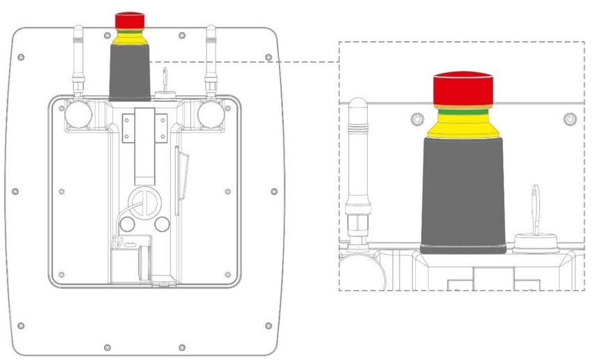
6.9 Emergency Stop (illuminated)
The emergency stop has 2-channel construction. The top of the emergency stop is illuminated
when it is active. For application info, see 16.2.6 Emergency Stop.
CAUTION Please note that the HGW 1033-32 emergency stop switch is simple an ad-
ditional emergency stop switch. It cannot be installed as the only emergency
stop on a machine.
Veuillez noter que l'interrupteur d'arrêt d'urgence HGW 1033-32 est un sim-
ple interrupteur d'arrêt d'urgence supplémentaire. Il ne peut pas être installé
comme seul arrêt d'urgence sur une machine.
Page 40 05.03.202010.1” WIRELESS HANDHELD OPERATING PANEL HGW 1033-32 6.10 Rotary Encoder The device is equipped with 3 rotary encoders, which can be analyzed via the application. Rotary encoders 1 + 2 are configured with 18 detents per turn, rotary encoder 3 has 36 de- tents per turn. The rotary encoders are evaluated with a separate hardware class in LASAL Class 2. 05.03.2020 Page 41
HGW 1033-32           10.1” WIRELESS HANDHELD OPERATING PANEL

7      Status and Error Messages

Status and error messages are shown in the status test of the LASAL CLASS software.
POINTER or CHKSUM messages can also be shown on the terminal screen.

    Number   Message            Definition                                 Cause/solution

      00     RUN RAM            The user program is currently running in   Info
                                RAM.
                                The display is not affected.
      01     RUN ROM            The user program stored in the program     Info
                                memory module was loaded into the
                                RAM and is currently running.
                                The display is not affected.
      02     RUNTIME            The total time for all cyclic objects      Solution:
                                exceed the maximum time; the time can
                                be configured using 2 system variables:    - Optimize the application's cyclic
                                                                             task.
                                - Runtime: Remaining time
                                                                           - Use higher capacity CPU.
                                - SWRuntime: Preset value for runtime
                                  counter                                  - Configure preset value
      03     POINTER            Incorrect program pointers were de-        Possible Causes:
                                tected before running the user program
                                                                           - The program memory module is
                                                                             missing, not programmed or de-
                                                                             fective.
                                                                           - The program in the user program
                                                                             memory (RAM) is not executa-
                                                                             ble.
                                                                           - The buffering battery has failed.
                                                                           - The user program has overwrit-
                                                                             ten a software error.

                                                                           Solution:
                                                                           - Reprogram the memory module,
                                                                             if the error reoccurs exchange
                                                                             the module.
                                                                           - Exchange the buffering battery.
                                                                           - Correct programming error
      04     CHKSUM             An invalid checksum was detected before    Cause/solution: s. POINTER
                                running the user program.

Page 42                                                                                         05.03.2020
10.1” WIRELESS HANDHELD OPERATING PANEL HGW 1033-32
05 WATCHDOG The program was interrupted via the Possible Causes:
watchdog logic.
- User program interrupts blocked
over a longer period of time (STI
command forgotten).
- Programming error in a hardware
interrupt.
- INB, OUTB, INW, OUTW instruc-
tions used incorrectly.
- The processor is defective.
Solution:
- Correct programming error.
- Exchange CPU
06 GENERAL ERROR General error This error occurs only during the de-
velopment of the operating system.
An error has occurred while stopping the
application over the online interface.
07 PROM DEFECT An error has occurred while programming Causes:
the memory module.
- The program memory module is
defective.
- The user program is too large.
- The program memory module is
missing.
Solution:
- Exchange the program memory
module
08 RESET The CPU has received the reset signal Info
and is waiting for further instructions.
The user program is not processed.
09 WD DEFECT The hardware monitoring circuit (watch- Solution:
dog logic) is defective.
- Exchange CPU
After power-up, the CPU checks the
watchdog logic function. If an error occurs
during this test, the CPU deliberately en-
ters an infinite loop from which no further
instructions are accepted.
10 STOP The program was stopped by the pro-
gramming system.
11 PROG BUSY reserved
12 PROGRAM LENGTH reserved
13 PROG END A memory module was successfully pro- Info
grammed.
14 PROG MEMO The CPU is currently programming the Info
memory module.
05.03.2020 Page 43HGW 1033-32 10.1” WIRELESS HANDHELD OPERATING PANEL
15 STOP BRKPT The CPU was stopped by a breakpoint in Info
the program.
16 CPU STOP The CPU was stopped by the program- Info
ming software.
17 INT ERROR The CPU has triggered a false interrupt Causes:
and stopped the user program or has en-
countered an unknown instruction while - A nonexistent operating system
running the program. was used.
- Stack error (uneven number of
PUSH and POP instructions).
- The user program was inter-
rupted by a software error.
Solution:
- Correct programming error.
18 SINGLE STEP The CPU is in single step mode and is Info
waiting for further instructions.
19 READY A module or project has been sent to the Info
CPU and it is ready to run the program.
20 LOAD The program is stopped and the CPU is Info
currently receiving a new module or pro-
ject.
21 UNZUL. MODULE The CPU has received a module that Solution:
does not belong to the project.
- Recompile and download the en-
tire project
22 MEMORY FULL The operating system memory /heap) is Causes:
too small. No memory could be reserved
while calling an internal function or an in- - Memory is only allocated but not
terface function is called from the applica- released.
tion.
Solution
- Clear memory
23 NOT LINKED When starting the CPU, a missing mod- Solution:
ule or a module that does not belong to
the project was detected. - Recompile and download the en-
tire project
24 DIV BY 0 A division error has occurred. Possible Causes:
- Division by 0.
- The result of a division does not
fit in the result register.
Solution:
- Correct programming error.
25 DIAS ERROR While accessing a DIAS module, an error Hardware problem
has occurred.
26 WAIT The CPU is busy. Info
Page 44 05.03.202010.1” WIRELESS HANDHELD OPERATING PANEL HGW 1033-32
27 OP PROG The operating system is currently being Info
reprogrammed.
28 OP INSTALLED The operating system has been rein- Info
stalled.
29 OS TOO LONG The operating system cannot be loaded; Restart, report error to SIGMATEK.
too little memory.
30 NO OPERATING Bootloader message. Restart, report error to SIGMATEK.
SYSTEM
No operating system found in RAM.
31 SEARCH FOR OS The bootloader is searching for the oper- Restart, report error to SIGMATEK.
ating system in RAM.
32 NO DEVICE reserved
33 UNUSED CODE reserved
34 MEM ERROR The operating system loaded does not Solution:
match the hardware configuration.
- Use the correct operating system
version
35 MAX IO reserved
36 MODULE LOAD ER- The LASAL Module or project cannot be Solution:
ROR loaded.
- Recompile and download the en-
tire project
37 BOOTIMAGE FAIL- A general error has occurred while load- Contact SIGMATEK
URE ing the operating system.
38 APPLMEM ERROR An error has occurred in the application Solution:
memory (user heap).
- Correct allocated memory access
error
39 OFFLINE This error does not occur in the control. This error code is used in the pro-
gramming system to show that there
is no connection to the control.
40 APPL LOAD reserved
41 APPL SAVE reserved
44 VARAN MANAGER An error number was entered in the Solution:
ERROR VARAN manager and stopped the pro-
gram. - Read LogFile
45 VARAN ERROR A required VARAN client was discon- Solution:
nected or communication error has oc-
curred. - Read LogFile
- Error Tree
05.03.2020 Page 45HGW 1033-32 10.1” WIRELESS HANDHELD OPERATING PANEL
46 APPL-LOAD-ERROR An error has occurred while loading the Cause:
application.
- Application was deleted.
Solution:
- Reload the application into the
control.
47 APPL-SAVE-ERROR An error has occurred while attempting to
save the application.
50 ACCESS-EXCEP- Read or write access to a restricted Solution:
TION-ERROR memory area. (I.e. writing to the NULL
pointer). - Correct application errors
51 BOUND EXCEEDED An exception error has occurred while ac- Solution:
cessing arrays. The memory area was
overwritten by accessing an invalid ele- - Correct application errors
ment.
52 PRIVILEDGED IN- An unauthorized instruction for the cur- Cause:
STRUCTION rent CPU level was given. For example,
setting the segment register. - The application has overwritten
the application program code.
Solution:
- Correct application errors
53 FLOATING POINT An error has occurred during a floating-
ERROR point operation.
60 DIAS-RISC-ERROR Error from the Intelligent DIAS Master. Restart, report error to SIGMATEK.
64 INTERNAL ERROR An internal error has occurred, all appli- Restart, report error to SIGMATEK.
cations are stopped.
65 FILE ERROR An error has occurred during a file opera-
tion.
66 DEBUG ASSERTION Internal error Restart, report error to SIGMATEK.
FAILED
67 REALTIME RUNTIME The total duration of all real-time objects Solution:
exceeds the maximum time; the time can-
not be configured. - Real-time Optimize the applica-
tion's real-time task (RtWork).
2 ms for 386 CPUs
- Real-time Reduce the clock time
1 ms for all other CPUs for the real-time task of all ob-
jects.
- Correct application errors
- CPU is overloaded in real-time
=> use a higher capacity CPU.
68 BACKGROUND The total time for all background objects Solution:
RUNTIME exceeds the maximum time; the time
can be configured using 2 system varia- - Optimize the application's back-
bles: ground task (background)
-BTRuntime: Remaining time - Use higher capacity CPU
-SWBTRuntime: Preset value for runtime - Set SWBTRuntime correctly
counter
Page 46 05.03.202010.1” WIRELESS HANDHELD OPERATING PANEL HGW 1033-32
70 C-DIAS ERROR A connection error with a C-DIAS mod- Cause:
ule has occurred.
- The cause of the error is docu-
mented in the log file
Solution:
- This depends on the cause
72 S-DIAS ERROR A connection error with an S-DIAS mod- Possible Causes:
ule has occurred.
- Real network does not match the
project
- S-DIAS client is defective
Solution:
- Analyze log file
75 SRAM ERROR An error occurred while initializing, read- Possible Causes:
ing or writing SRAM data.
- SRAM configured incorrectly
- Battery for powering the internal
program memory is empty
Solution:
- Analyze log file (Event00.log,
Event19.log)
- Check configuration
- Exchange battery for powering
the internal program memory
97 USER DEFINED 2 User-definable code.
98 USER DEFINED 3 User-definable code.
99 USER DEFINED 4 User-definable code.
100 C_INIT Initialization start; the configuration is run.
101 C_RUNRAM The LASAL project was successfully
started from RAM.
102 C_RUNROM The LASAL project was successfully
started from ROM.
103 C_RUNTIME
104 C_READY The CPU is ready for operation.
105 C_OK The CPU is ready for operation.
106 C_UNKNOWN_CID An unknown class from a stand-alone or
embedded object, or an unknown base
class was detected.
05.03.2020 Page 47You can also read