HOT TUB OWNER'S MANUAL - MODEL
←
→
Page content transcription
If your browser does not render page correctly, please read the page content below
HOT TUB OWNER’S MANUAL
                  MODEL:

PINNACLE PLUS –             PN 631, PN 740, PN 741,
                            PN 743, PN 850, PN 855

LUXURY –                    LX 4000, DX 5000,
                            LX 5000, LX 8000,
                            LX 9000, LX 11000

Ultra –                     U631, U743 (See note Page 8)

                  6101 45th St. N.
             St. Petersburg, FL 33714
                   800.304.9684
             www.PinnacleSpas.com
Part Number 7636
                                  SKUs: (1001-1011)
                                     Revised 6/14

                                 Owner’s Information

Dealer:
          Date Purchased:          __________________________
                Company:           __________________________
                 Address:          __________________________
               Telephone:          __________________________

Installer:
                Date Installed:    __________________________
                    Company:       __________________________
                     Address:      __________________________
                  Telephone:       __________________________

Hot Tub:
        Date Delivered:            __________________________
                 Model:            __________________________
                  Color:           __________________________
         Serial Number:            __________________________

Your unique hot tub serial number is located on a data plate outside the
cabinet at ground level directly below the topside control panel. When
calling for service, have your serial number in hand.

      MODEL 1005–LP–P–MA–NO–23
             (GCS)

      SERIAL #: ###########
              12345678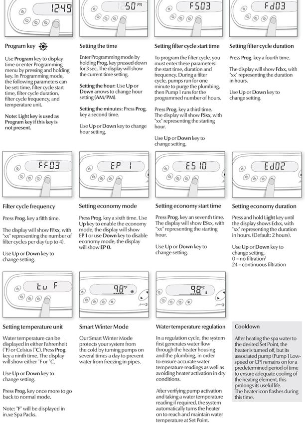
nn
   Piin
   P     ac
        na    eS
           clle  pa
                Sp  ass HHo  ott TTuubbO  Ow wn  ne        Ma
                                                   err’’ss M  nu
                                                             an  all
                                                                ua
                                   Coonntteennttss
                   TTaabbllee ooff C

      Introduction .................................................................................. 2
      Important Safety Information ....................................................... 3
      Location and Installation .............................................................. 7
      Electrical Specifications ............................................................... 9
      Startup ....................................................................................... 21
      Topside Control ......................................................................... 29
      Cover ......................................................................................... 42
      Water Management ................................................................... 43
      Frequently Asked Questions ..................................................... 44
      Troubleshooting ......................................................................... 47
      Maintenance and Care .............................................................. 48
      Shutdown / Winterizing .............................................................. 55
      Glossary ..................................................................................... 56
      Specifications ............................................................................. 57
      Certificate of Verification ............................................................ 65

Important: Pinnacle Spas is dedicated to offering you the best in customer
satisfaction and service. Be sure to read, complete, sign, and send in the
limited warranty card within 30 days of purchase to ensure you understand
what you are entitled to in terms of service. If you have any questions, you can
call our customer care center, at 800.304.9684.

                                               Printed in the U.S.A.

                     Version 3.5                Revised 6/2014             Part Number 7636

Copyright © 2011, Pinnacle Spas. All rights reserved. No portion of this manual may be reproduced in any manner without
express written permission of Pinnacle Spas. Pinnacle Spas™and Thermazone™ are trademarks of Pinnacle Spas. All
other brands, product names, company names, trade names, trademarks, and service marks used are the property of
their respective owners. Pinnacle Spas may make product modifications and enhancements. Specifications may change
without notice. International products may be configured differently to meet local electrical requirements. Dimensions are
approximate. Pinnacle Spas hot tubs are covered by U.S. Patent No. D573,261. Other patents pending.

                                                   Page 1
                                         For HELP, call 800.304.9684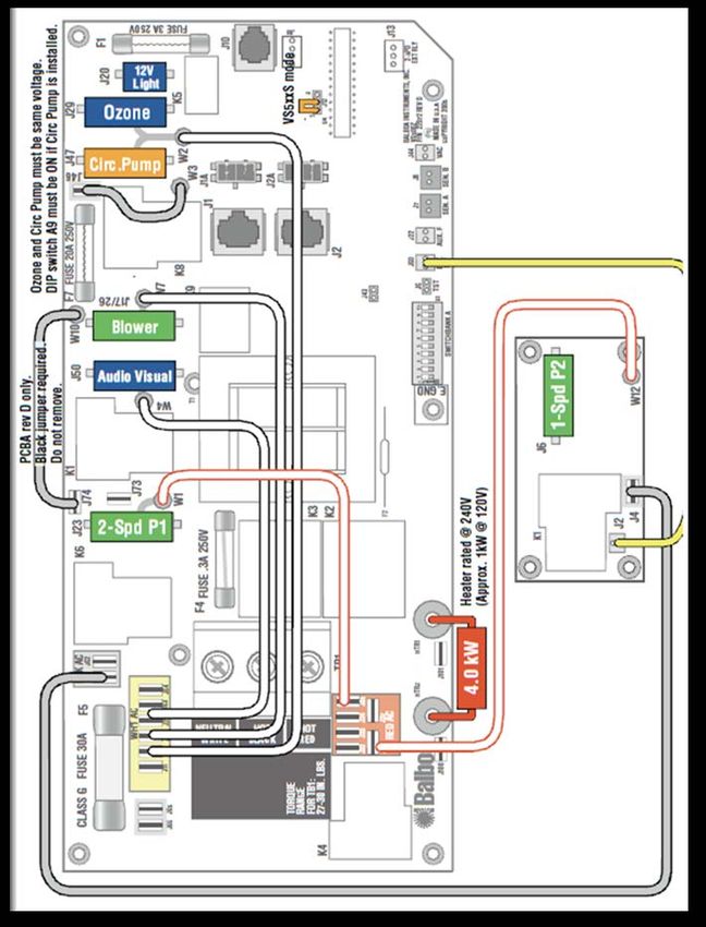
Introduction

Your choice of a Pinnacle Spas™ hot tub indicates that you are devoted
to excellence. The management and staff appreciate your patronage and
takes pride in the tradition of quality hot tubs that our company
represents.

To properly acquaint yourself with your hot tub, we suggest that you take
time to read through this manual before hook up and operation. Doing so
will familiarize you with important operating and safety procedures,
thereby ensuring an enjoyable experience right from the start.

If you need any more information than this manual provides, feel free to
visit our Web site at www.PinnacleSpas.com or call our customer care
center, at 800.304.9684.

   WARNING: This manual was written to ensure the proper use and
            installation of your hot tub. Any modifications to the
            procedures outlined in this manual may result in voiding
            your warranty.

This manual and its contents are subject to change without notice.
Although we have prepared this manual as accurate as possible, we are
not liable for errors or omissions; loss, injury, or damages caused by
improper installation; or use of hot tub (improper or otherwise).

You new hot tub is made with quality synthetic cabinet materials.
Synthetic materials won’t fade and are nearly invulnerable to mold and
mildew. Where wood splits, cracks, and stains, synthetic materials stand
in timeless perfection.

                                   Page 2
                         For HELP, call 800.304.9684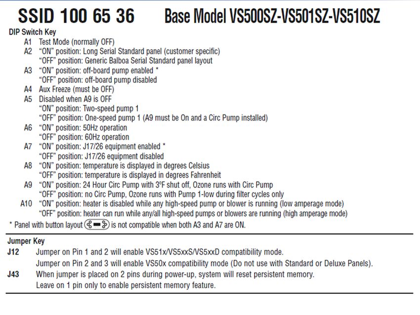
Important Safety Information
                    IMPORTANT SAFETY INSTRUCTIONS
                       SAVE THESE INSTRUCTIONS
Your physiological response to hot water depends on subjective factors such as
age, health, pregnant women, temperature sensitivities, chemical sensitivities,
and medical history. Always consult a physician before using a hot tub to
understand your particular tolerance and limitations.
                  READ AND FOLLOW ALL INSTRUCTIONS
WARNING – To reduce the risk of injury, do not permit children to use this
product unless they are closely supervised at all times.
A wire connector is provided on this unit to connect a minimum 8 American Wire
Gauge (AWG) (8.4mm2) solid copper conductor between this unit and any metal
equipment, metal enclosures of electrical equipment, metal water pipe, or conduit
within 5 feet (1.5 m) of the unit.
* For cord connected / convertible units:  Danger – Risk of injury.
Replace damaged cord, immediately. Do not bury cord. Connect to a grounded,
grounding type receptacle only.
** For units with GFCI:         Warning – This product is provided with a ground-
fault circuit interrupter located in the main panel. The GFCI must be tested
before each spa use.
DANGERS
            RISK OF ACCIDENTAL DROWNING: Extreme caution must be
            exercised to prevent unauthorized access by children. To avoid
            accidents, ensure that children cannot use this spa unless they are
            supervised at all times. Always cover the hot tub and use safety
            locks when it is not in use.
            RISK OF INJURY: The suction fittings in this spa are sized to match
            the specific water flow created by the pump. Should the need arise
            to replace the suction fittings or the pump, be sure that the flow rates
            are compatible. Never operate the spa if the suction fittings are
            broken or missing. Never replace a suction fitting with one rated less
            than the flow rate marked on the original suction fitting.
            RISK OF ELECTRIC SHOCK: Install at least 5 feet (1.5 m) from all
            metal surfaces. As an alternative, a spa may be installed within 5
            feet of metal surfaces if each metal surface is permanently
            connected by a minimum 8 AWG (8.4 mm2) solid copper conductor
            to the wire connector on the terminal box that is provided for this
            purpose.
            RISK OF ELECTRIC SHOCK: Do not permit any electric appliance,
            such as a light, telephone, radio or television, within 5 feet (1.5 m) of
            a spa. Do not operate such an appliance from either inside the hot
            tub or when you are wet, unless such appliances are built-in by the
            manufacturer.

                                      Page 3
                            For HELP, call 800.304.9684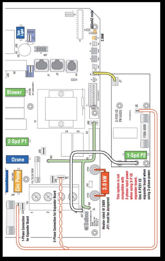
WARNINGS
       TO REDUCE THE RISK OF INJURY:
            •    The water in a spa should never exceed 40˚C (104˚F).
                 Water temperatures between 38˚C (100˚F) and 40˚C
                 (104˚F) are considered safe for a healthy adult. Lower
                 water temperatures are recommended for young children
                 and when spa use exceeds 10 minutes.
            •    Since excessive water temperatures have a high potential
                 for causing fetal damage during the early months of
                 pregnancy, pregnant or possible pregnant women should
                 limit spa water temperatures to 38˚C (100˚F).
            •    Before entering a spa/hot tub, the user should measure the
                 water temperature since the tolerance of water temperature
                 regulating devices varies.
            •    The use of alcohol, drugs or medication before or during
                 spa/hot tub use may lead to unconsciousness with the
                 possibility of drowning.
            •    Obese persons and persons with a history of heart disease,
                 low or high blood pressure, circulatory system problems, or
                 diabetes should consult a physician before using a spa.
            •    Persons using medication should consult a physician before
                 using a spa/hot tub since some medication may include
                 drowsiness while other medication may affect heart rate,
                 blood pressure and circulation.
       Do not connect auxiliary components (such as headphones, cables,
       and additional speakers) to the stereo (if equipped).
       Do not use a hot tub immediately following strenuous exercise.
       Do not use your hot tub alone.
       Lock the cover on your hot tub when not in use.
       Persons with infectious diseases should not use a hot tub.
       Replace audio components only with identical components.
       Do not leave the CD access door open on the stereo (if equipped).
       Some types of hair dye can react with the sanitizers in your hot tub
       water causing your hair to change color. Use at your own risk.
       Water normally splashes out of a hot tub during typical use. Install
       an adequate perimeter that provides sound footing.
       Do not turn your hot tub on/off from a wall switch, ground fault circuit
       interrupter, circuit breaker, fuse, or by plugging/unplugging it.
       Remove all jewelry, metal, and watches from your person before
       entering your hot tub.
       Keep all breakables away from the hot tub area.
       Maintain water balance in accordance with instructions.

                                 Page 4
                       For HELP, call 800.304.9684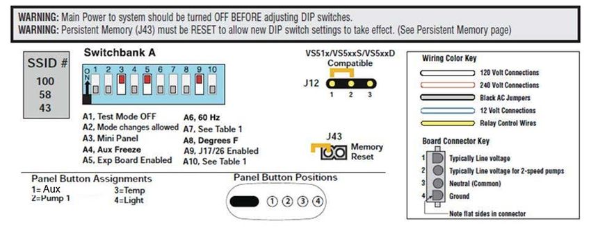
WARNING SIGN
                                 Warning Sign Must Be Posted – The red
                                 WARNING sign like the one shown is packed
                                 with your new hot tub. This sign must be posted
                                 in a prominent place in close proximity to the hot
                                 tub installation site immediately upon completion
                                 of hot tub installation.

Important: It is extremely important that this sign be permanently placed in clear
view of persons using the hot tub. Occasional hot tub users may not be aware of
some of the dangers hot water poses to pregnant women, small children,
seniors, and people under the influence of alcohol. If you did not receive a
warning sign or your sign has become damaged, please call your local dealer for
a replacement.
HYPERTHERMIA
To reduce the risk of injury, the water temperature in a hot tub should never
exceed 104˚F (40˚C). Water temperatures between 100˚F (38˚C) and 104˚F
(40˚C) are considered safe for a healthy adult. Lower water temperatures are
recommended for young children, senior citizens, persons with sensitivities, and
when hot tub use exceeds 10 minutes.
WATER TEMPERATURE IN EXCESS OF 100˚F (38˚C) MAY BE INJURIOUS
TO YOUR HEALTH.
Hyperthermia occurs when the internal temperature of the body reaches a level
several degrees above the normal body temperature of 98.6˚F (37˚C). The
symptoms of hyperthermia include drowsiness, lethargy, and an increase in the
internal temperature of the body. The effects of hyperthermia include:
            Unawareness of impending hazard
            Failure to perceive heat
            Failure to recognize the need to exit hot tub
            Physical inability to exit hot tub
            Fetal damage in pregnant women
            Unconsciousness and danger of drowning
If you sense any of the symptoms of hyperthermia, safely exit the hot tub
immediately.

                SAVE THESE INSTRUCTIONS
BASIC SAFETY GUIDELINES
Your hot tub is meant to be enjoyable, healthful, and relaxing. Below are
some basic safety guidelines to follow every time you use your hot tub.
•   Always check the temperature of your hot tub before entering. High
    water temperatures can be hazardous to your health.
•   Persons suffering from heart disease, diabetes, high or low blood
    pressure, and pregnant women should consult a doctor before using
                                      Page 5
                            For HELP, call 800.304.9684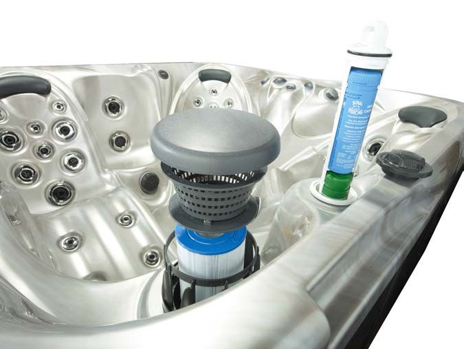
your hot tub.
•   Persons under the influence of medication, drugs, or alcohol should
    not be allowed into your hot tub.
•   Remove all jewelry, metal, and watches from your person before
    entering your hot tub.
•   Do not allow children to use your hot tub without continuous
    supervision of an adult.
•   Do not use your hot tub alone.
•   Test the ground fault circuit interrupter (GFCI) breaker prior to using
    your hot tub each time to ensure it operates properly.
•   Any electrical devices near your hot tub must be GFCI protected and
    out of reach from inside the hot tub.
•   Keep all breakables away from the hot tub area.
•   Lock the cover on your hot tub when not in use.
•   Enter and exit the hot tub slowly. Wet surfaces can be slippery.
• Prolonged immersion can be hazardous to your health.
Maintain water chemistry in accordance with manufacturer’s instructions.

•   The hot tub is not to be used by persons with reduced physical,
    sensory or mental capabilities, or lack of experience and knowledge,
    unless they have been given supervision or instruction

BASIC WATER QUALITY GUIDELINES
•   During the initial filling of the spa, add a sequestering agent to
    combat suspended minerals in the water. Allow water to circulate
    and filter for at least 12 hours before adding any other chemicals.
•   Test water for PH, total Alkalinity, and Calcium hardness. The PH
    should be 7.2-7.8 and the total Alkalinity 80-180 PPM. Calcium
    hardness levels should be maintained between 150 and 400 PPM.
    Adjust PH and total Alkalinity (TA) utilizing the directions on the
    chemical bottles. Wait 15-30 minutes, test and adjust if necessary.
•   Add 2 ounces of concentrated chlorinating granules (sodium Dichlor-
    s-triazinetreone) on initial start up to begin sanitizing the spa water. It
    is important not to add the chlorinating granules until the PH,
    alkalinity and calcium hardness have been adjusted to their proper
    levels.
•   Check spa water with test strip for proper sanitation levels and adjust
    accordingly to the proper levels. Free chlorine should be 2-4 PPM.
•   We recommend a minimum level of 2 PPM residual chlorine be

                                    Page 6
                          For HELP, call 800.304.9684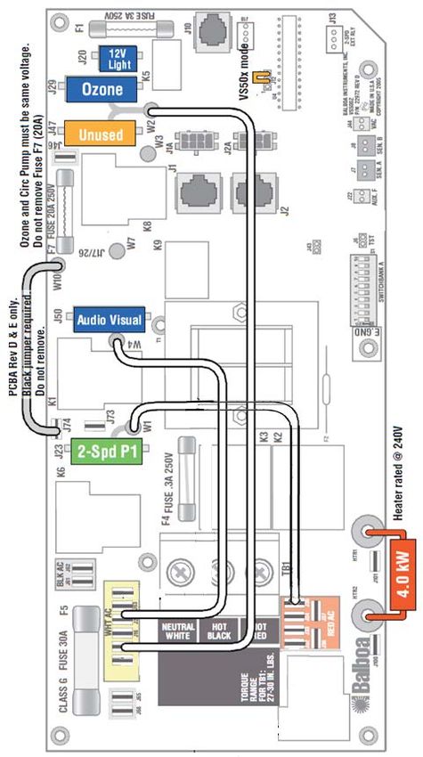
maintained in spa water. Be sure the pumps are running when
     adding chlorine or non chlorine shock/oxidizer.
•    Add 1 ounce of non-chlorine shock/oxidizer or ½ ounce of chlorine to
     the spa water after each spa use.

FOR HOT TUBS EQUIPPED WITH AUDIO COMPONENTS
Audio components are optional and not available on all models.

    WARNING: Prevent Electrocution: Do not connect any auxiliary
               components – for example, cable, additional speakers,
               headphones, etc., – to the system.

    Caution: Risk of Electric Shock: Do not leave audio compartment door
              open. Replace audio components only with identical components.

       Location and Installation

Proper planning is an important consideration when installing your new
hot tub. Site selection is a critical step and requires serious thought.
Planning ahead makes the installation process easier. The following
information is provided to assist you in site preparations.

1) Always comply with local building codes and obtain any necessary
   permits. You may also need to consult with an engineer to address
   your specific design needs.
2) Contact an electrician to assess your electrical needs, install wiring,
   and assure a safe operation.
3) Position your hot tub with proper access to water, drainage, and
   electricity.
4) Place your hot tub on a uniform solid, flat surface designed to
   properly support its weight. For external installations, a 4-inch (10
   cm) thick cement pad suffices. See page 9 for conduit entry locations
   for your model hot tub.
5) For internal installations, check the load carrying capabilities of the
   floor on which the hot tub will reside. Most homes meet the
   requirement of 80 pounds per square foot.
                                     Page 7
                           For HELP, call 800.304.9684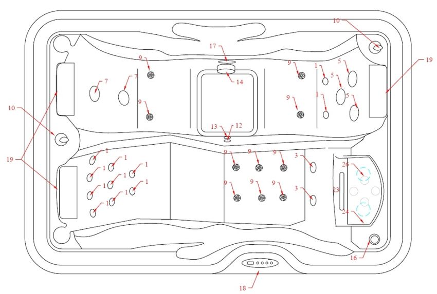
6) Assure that your hot tub will fit into the space you have chosen and
   the delivery route will accommodate its large size.
7) Provide adequate ventilation for the humidity created by your hot tub.
   In most cases, a Hot Tub Hard Cover is sufficient.
8) Protect the pump and all equipment from the weather by ensuring
   the cabinet panels are secure at all times.
9) Allow 36 inches (1 meter) of unobstructed access to all sides of your
   hot tub for normal servicing. Your hot tub is not designed to be
   recessed in the ground or in a deck.

                                                       4 inch (10 cm)
                      36 inch                          Concrete slab
                        (1 m)         Hot Tub
                     clearance

                  Figure 1 – Clearances and Support
The following dimensions can be used to determine the proper location
of submerged conduits in concrete slab installations. All dimensions are
made from the outside of the hot tub’s frame with the access panels
removed. The topside control panel is shown at bottom of diagram for
reference.

        Figure 2 – Conduit Entry Location Reference Points

                                   Page 8
                         For HELP, call 800.304.9684
Model Dimension A Dimension B
LX 4000 (1006) 22” (56 cm) 22” (56 cm)
LX/DX 5000 (1004) 18” (46 cm) 11” (28 cm)
LX 8000 (1001B) 20” (51 cm) 13” (33 cm)
LX 9000 (1003) 20” (51 cm) 13” (33 cm)
LX 11000 (1002) 22” (56 cm) 12” (30 cm)
PN 631 (1011) 12” (30.5 cm) 9” (23 cm)
PN 741 (1007) 29” (73.5 cm) 15” (38 cm)
PN 743 (1009) 27” (68.5 cm) 13” (33 cm)
PN 850 (1008) 25” (63.5 cm) 13” (33 cm)
PN 855 (1010) 28” (71 cm) 14” (35.5 cm)
PN 740 (1012) 34” (85 cm) 11” (28 cm)
Table 1 – Conduit Entry Location Dimensions
Note : Model U631 is similar to DX5000, Model U743 is similar to LX8000
10) Consider positioning your hot tub out of or adequately protecting it from the
wind. Just as people can get cold on cool/windy days so can your hot tub.
Windy environments can significantly increase operating costs.
11) Consider using an insulating pad. In cold climates, the ground can rob heat
from the hot tub and increase your operating costs. Consider using a
suitable, outdoor insulating pad in such environments.
12)
Electrical Specifications
Important – Qualified and licensed electricians must perform all
electrical hookups. The following specifications must be followed in order
to ensure proper performance and safety.
All hot tubs can supplied with Balboa or Gecko control and must be wired with a
50 or 60 Amp breaker (or according to IEE wire regulations for export models).
Failure to do so will cause equipment damage and will not be covered under your
Page 9
For HELP, call 800.304.9684warranty. All hot tubs must be over current protected with a built-in GFCI (or RCD
for export models) in the service panel.
Volts Freq. Rating GFCI Wire size from GFCI Equipment
Model (V) (Hz) (A) (A) to Main Panel *† Pack
6-3 plus ground (up to 130’)
LX 4000, VS515Z or
240 60 40 50 4-3 plus ground (up to 230’)
LX/DX 5000 VS500Z
2-3 plus ground (up to 360’)
LX 8000,
LX 9000,
LX 11000,
240 60 48 60 “ VS510SZ
PN 741,740,
743, 850, 851,
855
VS500Z
PN 631 240 60 40 50 “
PN 741, 740,
743, 850, 851, 240 60 48 60 “ IN.XE
855
PN 631 240 60 40 50 “ IN.XE
Table 2 – Domestic (US/Canada) Wire Size Chart
Volts Rating RCD Wire size from RCD Equipment
Model (V) (A) (A) to Main Panel ठPack
LX 4000, LX/DX
5000, LX8000,
LX9000,
LX 11000, 220- 1x32 IEE Wire 3x4 mm2
GS510SZ
PN631, PN741, 240 2x16 Regulation 5x1.5 mm2
PN740, PN743,
PN850, PN851,
PN855
PN 631, 741,
740, 743, 850, “ “ “ “ IN.XE-CE
851, 855
Table 3 – Export Wire Size Chart
WARNING: Starting an incorrectly wired hot tub could cause severe damage
to the mechanical equipment or even bodily harm. Have your licensed electrician
verify GFCI (or RCD) wiring with the schematics on pages 10-20 prior to starting
the hot tub or call the technical support line at 800.304.9684.
Caution: Failure to abide by specifications listed may result in damage to the
equipment and will void the warranty.
* Wire size may need to be reduced at GFCI to fit into the breaker
†
Solid copper
‡ Wire size may need to be reduced at GFCI to fit into the breaker
§
Solid copper
Page 10
For HELP, call 800.304.9684WARNING: Disconnect the electrical power before servicing. Before
obtaining access to terminals, all supply circuits must be disconnected.
Caution: Test the GFCI (or RCD) before each use.
Our hot tubs are certified by Intertek Testing, SNAa Ltd.
Ontario, Canada to CSA-C22.2 No. 218.1-M89 and
ANSI/UL 1563 standards.
Parts with extra low voltage not exceeding 12v must be inaccessible to a person
in the hot tub. Earthed appliances must be permanently connected to fixed
wiring. Parts incorporating electrical components, except remote control devices,
must be located or fixed so that they cannot fall into the hot tub.
Means for disconnection must be used in fixed wiring in accordance with wiring
rules.
Important – To allow the 240V GFCI to function properly, connect the white Neutral wire
from the hot tub to the Neutral terminal on the GFCI breaker, not the Neutral bus in the
GFCI breaker box. An improperly connected Neutral causes the GFCI breaker to trip.
Figure 3 – GFCI Wiring
Page 11
For HELP, call 800.304.9684Page 12 For HELP, call 800.304.9684
Figure 4 – European 1x32A Wiring Diagram
All wiring is 3x4mm2, solid copper
See wire size chart on page 10.
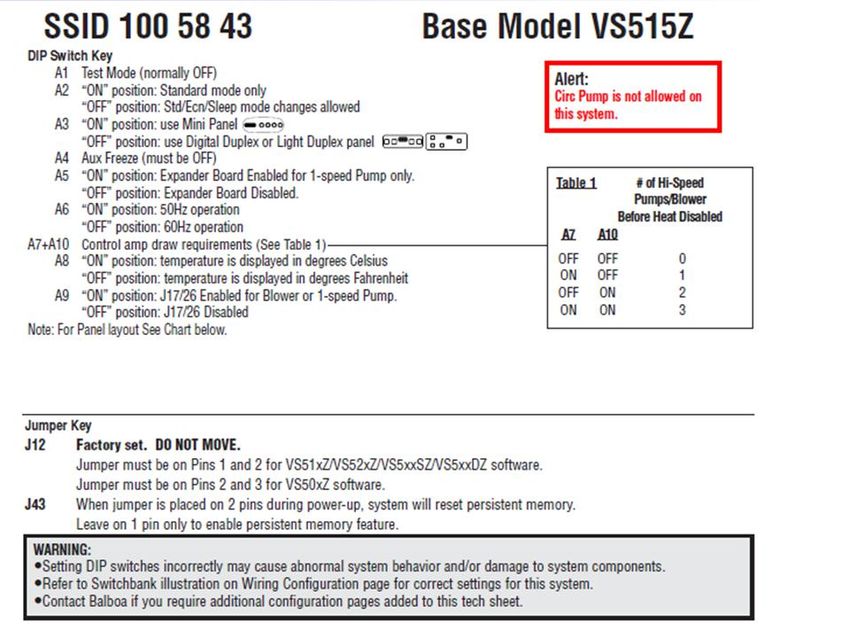
Note: Make sure that the DIP switches in the hot tub Pack are
properly set for 50Hz operation and Jumper A is in place.
Page 13
For HELP, call 800.304.9684Figure 5 – European 2x16A Wiring Diagram
All wiring is 5x1.5mm2, solid copper
See wire size chart on page 10.
Note: Make sure that the DIP switches in the hot tub Pack are
properly set for 50Hz operation and Jumper A is
removed.
Page 14
For HELP, call 800.304.9684Figure 7 – Domestic Wiring Diagram for LX 8000, LX 9000, LX 11000,
PN740, PN741, PN743, PN850, PN851, PN855 (option) Models. Single-
phase 240V with Balboa VS510SZ Control Pack.
See wire size chart on page 10.
Page 15
For HELP, call 800.304.9684Figure 8 – Board Diagram for LX 8000, LX 9000. LX 11000 with VL 700s
and PN740, PN741, PN743, PN850, PN851 With VL 600s
VL 700s VL 600s
9A 9B
A7 in Switchbank “A” set to
Single-phase 240V Domestic version off
Figure 9A – Panel Button Positions for LX 8000, LX 9000 and LX 11000
Models Single-phase 240V Domestic version
Figure 9B – Panel Button Positions for PN740, PN741, PN743, PN850,
PN851, and PN855
Page 16
For HELP, call 800.304.9684Page 17 For HELP, call 800.304.9684
Figure 10A – Domestic Wiring Diagram for LX 4000 and LX/DX 5000
       Models Single-phase 240V with VS515Z Control Pack.
                  (See wire size chart on Pg. 10.)

                              Page 18
                     For HELP, call 800.304.9684
Figure 11 – Board Diagram for LX 4000 and LX/DX 5000 Models
Single-phase 240V Domestic version
Page 19
For HELP, call 800.304.9684U.S. AND CANADA WIRING VS500Z
Figure 10B – Domestic Wiring Diagram for PN631
Model Single-phase 240V for VS500Z Control Pack.
Page 20
For HELP, call 800.304.9684Figure 11 – Board Diagram for VS500z
Single-phase 240V Domestic version
Page 21
For HELP, call 800.304.9684EXPORT WIRING ALL MODELS
Figure 12 – Export Wiring Diagram for all models for GS510SZ
Control Pack (See wire size chart on Pg. 10.)
Page 22
For HELP, call 800.304.9684Figure 13 – Board Diagram for all models.
Export version for GS510SZ Control Pack.
Figure 14
– Panel Button Positions for all models Export version.
Page 23
For HELP, call 800.304.9684Startup
Important – Read these step-by-step startup procedures before starting
your hot tub. Failure to follow any of these steps listed may result in
damage to the equipment and may void your warranty.
Note: If you are unsure of any of the above startup procedures, please
call our customer care center, at 800.304.9684. For best results, read
each step in its entirety before proceeding.
Caution: Running the hot tub pump dry (without water running
through it) can cause IMMEDIATE damage and will void the
warranty! Be sure that the hot tub is installed properly in
accordance with the instructions in this manual.
Refer to the following picture for an explanation of your hot tub’s controls,
components, and technical terms. Note that not all models have all
features and components.
Waterfall
Pillow
Water Jet
Air Control
Light Valve
Intake
Waterfall
Off/On
Topside Control
Filtration
Canister
Cabinet
Drain Valve Panel
Figure 15 – Callouts
Page 24
For HELP, call 800.304.9684Before Adding Water
Before adding water, go through these simple steps now to prevent
common issues when setting up your hot tub for the first time. Verify that
the following have all been rechecked.
1. Turn off all power to the hot tub at the main breaker panel.
2. Open the side panels to access the internal components.
3. Check that all slide valves are opened
(T-handles pulled out) to the heater and
all pumps.
4. Check that there are no obvious signs of
loose wires or broken pipes.
Figure 16 - Valve Open/Closed
5. Check that the two heater unions
are hand tight.
Caution: Do not use a wrench.
Over-tightening may
cause damage to unions
and gaskets, which will
not be covered under Figure 17 - Unions Tight
warranty.
6. Check that the unions on all pumps are tight.
7. Clean out any foreign debris from within the service access area or
inside of the hot tub itself.
8. With the drain open and filters removed, thoroughly rinse out the hot
tub with warm water until the drained water runs clear. Run water
through the filtration canister and jet lines to remove any incidental
dust, dirt, and debris that may have accumulated during shipment or
installation. Drain all water completely.
9. Make sure that the hot tub drain valve is closed and the cap is on
tight (see page 50).
10. Install the filter(s) in the filtration canister.
11. Check that all of the hot tub jets are open (turned full counter-
clockwise).
12. Now is the best time to clean and polish the surfaces of your hot tub
(see pages 44).
Page 25
For HELP, call 800.304.9684Filling Your Hot Tub
Now it's time to fill your hot tub with water. Do not
turn on the electricity yet until the hot tub is
completely filled. To properly fill your hot tub:
1. Make sure that the filters (in the filtration
canister) are gently screwed into place. Turn
them clockwise until they stop being careful
not to over-tighten them (this avoids cracking
the filter).
2. Connect a standard garden hose to a faucet
with regular cold tap water (not softened
water or hot water).
Figure 18 – Filtration Canister
Caution: The water from your hot water tank should not be used to fill
the hot tub.
3. Put the pre-filter (if equipped **) on the other end of the hose, point
the pre-filter into a suitable drain, turn on the water, and allow any
sediment to be flushed down the drain. Once the water stream runs
clear, turn off the hose.
4. Put the pre-filter (if equipped) into the filtration canister and turn on
the hose.
5. Fill slowly. If too much water pressure is used, foaming water can
force air into the pipes and cause startup problems.
Important: To assure that the pump is properly primed, fill the hot
tub through the filter area only.
6. Fill the hot tub until the water level is about 1” above all jets (or about
½” below the pillow). Do not over fill.
Note: Every person entering a hot tub displaces a given volume of
water, so adjust water level to the number of people regularly using
the hot tub.
Turn off the hose and check again for any small leaks.
**
Pre-filters are available by calling 800.304.9684
Page 26
For HELP, call 800.304.9684Operational Checks for all Models with Balboa Control
Caution: Do not turn on any pump until your hot tub is properly filled
with water. Running any pump without water in your hot tub
can cause IMMEDIATE damage, which is not covered
under warranty!
By now you have rechecked your hot tub’s mechanical connections and
filled it with water to about 1” above all jets by adding cold tap water
through the pre-filter (if equipped). Turn on power to the hot tub at the
main breaker panel and test the operation of the electrical system. If you
encounter a problem, please reference the troubleshooting guide on
page 47.
1. Turn on the breaker and test the operation of the Ground-Fault
Circuit Interrupter (GFCI) breaker by pushing the small button. This
should automatically trip the hot tub's circuit breaker.
DANGER: If this breaker does not trip, immediately call your
electrician. Do not use your hot tub!
Only if pushing this button successfully trips this circuit breaker
should you reset this breaker and proceed to the next step.
2. Go to the topside control panel. The hot tub first goes into a 5-minute
Priming mode, indicated by “Pr” message. Water heating is disabled
during priming. To exit Priming mode and begin normal hot tub
operation, press “Up” or “Down” button.
3. Press the Jets (Jets 1) button. You should hear the pump turn on,
see water circulating, and see the Jets light illuminate on the panel.
4. Press the Jets (Jets 1) button again. You should hear the pump turn
on a higher speed.
Caution: If water is not flowing from the jets after 2 minutes, turn
the power off at the main panel and bleed air from the
system (see page 46). Turn the power on again.
Sometimes momentarily turning the pump off/on will
help to prime. Only do this four times.
Page 27
For HELP, call 800.304.96845. If the water is running smoothly through the lines, open the air
control valve to the jets and you should see an increase in jet
pressure. Check and adjust the water and airflow of every jet if
necessary.
Each jet in your hot tub can be adjusted for massage intensity and
directional flow. Turn the outer jet dial counterclockwise to increase
the water volume and clockwise to turn it off. Pivot the angle of a jet
to achieve an optimal massage.
An air mixture intensifies the level of your massage. Turn the air
control valve counterclockwise to increase the air mixture and
clockwise to turn it off.
To minimize heat loss, close the air control valve when your hot tub
is not in use.
6. Press the Jets (Jets 1) button a third time to turn off the pump.
Note: The pump remains on if filtration or heat is needed.
7. Press the Light button to turn on the light. Verify that the light is on.
8. Press the Light button a second time to turn off the light.
9. If equipped, press the Jets 2 button. You should hear the pump turn
on, see water circulating, and see the Jets2 light illuminate on the
panel.
10. Press the Jets 2 button again to turn off the pump.
11. If equipped, press the Blower button. You should hear the blower
turn on, see water bubbling, and see the blower light illuminate on
the panel.
12. Press the Blower button again to turn off the blower.
Water Balancing
Note: Perform water balancing weekly and whenever your water is
changed (or when your hot tub is first filled). Once your hot tub
reaches 95ºF, add the necessary chemicals to stabilize your water
chemistry (pH, hardness, and total alkalinity, etc.). Then add the
start-up chemicals* the water. Turn Pump 1 on high speed
immediately to distribute it evenly.
Test Range
Note: Test strips and Total Alkalinity 80-180 ppm
water balancing chemicals
are available by calling pH 7.2-7.8
800.749.8003 or visiting Calcium 150-400
www.hottubparts.com Hardness ppm
Bromine 1.0-2.0 ppm
Table 4 - Recommended Ranges
for Balanced Water
Page 28
For HELP, call 800.304.9684Topside Control
There are various styles of topside control panels used domestically and
internationally in the Pinnacle Spas series of hot tubs. Basic operations common
to all control panels are provided next.
Setting the Water Temperature
Use Warm/Cool [or Temp for the 4-button panel] to set the water temperature
you desire. The temperature setting displays for five seconds to confirm your new
selection. The set point icon indicates that the display shows the desired
temperature (not the actual water temperature). The default temperature setting
is 100ºF.
Setting the Filtration Cycles
To set the filtration cycle start time, reset the controller by power cycling (power
off). After the five minute priming, the filtration cycle starts 12 hours later. You
can also skip the priming period by pressing Warm/Cool [or Temp for the 4-
button panel].
Filter duration is programmable for 2, 4, 6, 8 hours or for continuous filtration
(indicated by “FC”). The default filter time is 2 hours. To change the filter cycle
duration, press Warm/Cool [or Temp for the 4-button panel], then Mode [Jets].
Press Warm/Cool [Temp] to adjust. Press Mode [Jets] to exit.
When Jets 1 [or Jets for the 4-button panel] LED is ON and the Heat LED is OFF,
the hot tub is in filtration mode.
Other operations are slightly different between each of the three control panels.
Step-by-step programming and a quick reference summary are provided next.
LX 8000, LX 9000 AND LX 11000 – (VL700S)
The topside control panel operates and programs your hot tub. Basic button
functions are described next.
Figure 19 – Topside Callouts for VL700S Controls
LX 4000, LX/DX 5000, and pn631 Domestic – (MVP 260)
Page 29
For HELP, call 800.304.9684Figure 20 – Topside Callouts for MVP 260 Controls.
LX 4000 and lx 5000 (Export Only) – (VL600S)
Figure 21 – Topside Callouts for VL600S Controls.
PN740, PN741, PN743, PN850, PN851, and pn855
Initial Start Up
When your hot tub is first actuated, it will go into Priming mode, indicated by “Pr.”
The priming mode will last for less than five minutes. Press “WARM” or “COOL”
to skip Priming Mode and then the hot tub will begin to heat and maintain the
temperature in “Standard Mode.”
Page 30
For HELP, call 800.304.9684Warm/Cool Buttons (LX 8000, LX 9000 and LX 11000) (Set
Temperatures between 80°F - 104°F / 26°C - 40°C)
The startup temperature is set at 100°F/37°C. The last measured temperature is
constantly displayed on the LCD and is current only when the pump has been
running for at least two minutes. To display the set temperature, press the
“WARM” or “COOL” button once. To change the set temperature, press the
“WARM” or “COOL” button a second time before the LCD stops flashing. Each
press of the “WARM” or “COOL” button will continue to raise/lower the set
temperature. After three seconds, the LCD will stop flashing and display the
current hot tub temperature.
Temp Button (LX 4000 and LX/DX 5000) (Set Temperatures between
80°F - 104°F / 26°C - 40°C)
To display the set temperature, press the “TEMP” button once. To change the set
temperature, press the “TEMP” button a second time. Before the LCD stops
flashing, continue to press the “TEMP” button to raise/lower the set temperature.
If the opposite direction is desired, release the “TEMP” button and let the screen
revert to the current water temperature. Press the “TEMP” button to display the
set temperature and again to make the temperature change in the desired
direction.
Jets 1 and Jets 2 Buttons
Press the “JETS 1” button once to activate the low speed of Pump 1. Press it a
second time to activate the high speed of Pump 1. Press it a third time to turn off
Pump 1. If left running, the high speed of Pump 1 automatically will turn off after
15 minutes and the low speed of Pump 1 automatically will turn off after 4 hours.
The low speed of Pump 1 runs when the “JETS 2” Pump 2 is on. It may also
active for at least two minutes every half hour to detect the hot tub temperature
and then to heat to the set temperature if needed (depending on mode). When
the low speed turns on automatically, it cannot be deactivated from the panel,
however the high speed may be activated.
Press JETS 2 once to activate Pump 2. Press it again to turn off Pump 2.
Aux Button
Press the “AUX” button once to turn on the Air Jet Bubbler (blower). Press it a
second time to turn off the Air Jet Bubbler. If left running, the Air Jet Bubbler
automatically will turn off after 15 minutes.
Light
Press the “LIGHT” button once to turn on your hot tub lights. Press the LIGHT
button multiple times to cycle through the many available color patterns. Press
the LIGHT button again to turn off the LED light system. If left on, the lights
automatically turn off after 4 hours.
Page 31
For HELP, call 800.304.9684Mode
Your hot tub operating mode is changed by first pressing the “WARM” or “COLD”
button, then pressing the “MODE” button (in the LX 8000, LX 9000 and LX 11000
– and LX 4000 and LX 5000 export) or the “LIGHT” button (in the LX 4000 and
LX/DX 5000).
• Standard Mode is programmed to constantly maintain the desired
temperature. “Std” (or “St” in the LX 4000 and LX/DX 5000) will be
displayed momentarily when you switch into standard mode.
• Economy Mode heats the spa to the set temperature only during filter
cycles. “Ecn” (or “Ec”) will display solid when temperature is not current
and will alternate with temperature when temperature is current.
• Sleep Mode heats the hot tub to within 20°F/10°C of the set
temperature only during filter cycles. “SLP” (or “SL”) will display solid
when temperature is not current and will alternate with temperature
when temperature is current.
Preset Filter Cycles
The first filter cycle begins six minutes after the hot tub is energized. The second
filter cycle begins 12 hours later. Filter duration is programmable for 2, 4, 6 or 8
hours – or for continuous filtration indicated by “FI LC” (or “FC”). The default filter
time is two hours.
To program filter cycles, press “WARM” or “COOL” and then “JETS.” Press
“WARM” or “COOL” again to adjust to your desired setting. Press “JETS” again
to exit filter cycle programming.
The low speed of the 2-speed pump runs during filtration and the ozonator will be
enabled.
Smart Winter Mode
If the system (sensor located inside heater) detects ambient conditions
below 44ºF/6.7ºC, it automatically enters the Smart Winter Mode for
period of four minutes after it detects the hot tub temperature has risen
to 45ºF/7.2ºC.
Page 32
For HELP, call 800.304.9684Startup Procedure for all PN Model with Gecko Control
Figure 22 (K450 Topside Control)
1. Go to the topside control panel and look at the display. The spa first
goes through a startup sequence after which pump 1 high, pump 2 (if
equipped) will run for a one minute purge cycle. Pump 1 (low) will then
start in filtration cycle.
2. Press the Jets 1 button. You should hear the two-speed pump turn on at
high speed, see water circulating, and see the Jets icon illuminated on
the panel.
Caution: If water is not flowing from the hydrotherapy jets after 2
minutes, turn the power off at the main panel and bleed the air from the
system (see page 43). Turn the power on again. Sometimes
momentarily turning the pump off/on will help prime the pump. Do this
no more than three times.
3. If the water is running smoothly through the lines, open the seat(s)
manifold air control valves and you should see an increase in jet
pressure. Check and adjust the water and airflow of every jet if
necessary.
Each direction hydrotherapy jet in your spa can be adjusted for
massage intensity and directional flow. Pivot the angle of a jet to
achieve an optimal massage.
Adding air mixture intensifies the level of your massage. Turn the
seat(s) manifold air control valves counterclockwise to increase the air
mixture and clockwise to turn it off.
To minimize heat losses, close all seat(s) manifold air control valves
when your spa is not in use.
Page 33
For HELP, call 800.304.96844. Press the Jets1 button a third time to turn off the two speed pump.
Note: This pump remains on if filtration or heat is needed.
5. Press the Light button to turn on the LED light. Verify that this light is on.
6. Press the Light button a second time to turn off this light.
7. If equipped, press the Jets 2 button. You should hear the second pump
turn on, see water circulating, and see the Jets 2 icon illuminated on
the panel.
Note: If the water does not move through second pump jets repeat
same procedure as for first pump.
8. Press the Jets 2 button again to turn off this pump.
Water Balancing for PN Models
Note: Your Pinnacle Plus (PN model) hot tub comes with a built-in SPA
FROG sanitizing system. Depending on the area you live in and the
local regulatory rules, your SPA FROG consists of some
combination of a mineral cartridge and a bromine cartridge
manufactured directly in the plumbing line of your hot tub. Here’s
how it works:
The SPA FROG In-Line System is made up of (A) a FROG cap that is
easily distinguishable among the fittings on the top of the spa, (B) a
cartridge holder that pulls out of the system, (C) a mineral cartridge
that controls bacteria in the water and (D) a bromine cartridge that
helps support the minerals while oxidizing contaminants like body
oils. The cartridges are adjustable to meet your specific spa water
care needs.
NOTE: See page 66 for a photo of what the Spa Frog In-Line
Sanitation System looks like installed in a PN spa.
Page 34
For HELP, call 800.304.9684SPA FROG START UP: After you have filled and balanced the water in your hot
tub according to the chart in Table 4, proceed with the SPA FROG as follows:
*NOTE: Bromine levels are lower only when used with FROG minerals. Use a
metal out or sequestering agent if fill water is high in metals. Wait 24 hours
before continuing start up. Shock hot tub to establish a 1.0-2.0 ppm bromine or
chlorine residual. Add directly to hot tub water. Do NOT add through the SPA
FROG In-Line System. When spa reaches 95 degrees, set the mineral and
bromine cartridges according to the directions below and insert them into the
System.
Test Range
Note: Test strips and Total Alkalinity 80-180 ppm
water balancing chemicals
are available by calling pH 7.2-7.8
800.749.8003 or visiting Calcium 150-400
www.hottubparts.com Hardness ppm
Bromine 1.0-2.0 ppm
Table 5 - Recommended Ranges
for Balanced Water Using Spa Frog
Page 35
For HELP, call 800.304.9684ADJUSTING AND REPLACING SPA FROG BROMINE CARTRIDGE:
As every hot tub is different, finding the right setting for the bromine
cartridge will require monitoring your usage for the first week or two.
Begin with an initial setting of 3 (if you set your filtration cycle to 1 hour a
day) or 2 (if you set your filtration cycle to 2 or more hours a day) and
monitor bromine levels before each use. Adjust the cartridge by one
setting per use until a 1.0-2.0ppm level has been achieved. To adjust
cartridge, remove from system and turn to the next higher setting if the
bromine level is low, or the next lower setting if the bromine level is high.
The bromine cartridge needs to be replaced when empty. Drain water to
ensure empty then discard in trash. On most hot tubs, it will last between
2 – 4 weeks. Always maintain at least 1.0 ppm bromine level.
ADJUSTING AND WHEN TO REPLACE SPA FROG MINERAL
CARTRIDGE: Set SPA FROG Mineral Cartridge wide open on #6 by
holding the bottom and turning the top until the number 6 appears in the
setting window. The SPA FROG Mineral Cartridge must be replaced
every 4 months. After four months of use, or when draining and refilling
the hot tub with fresh water, discard SPA FROG Mineral Cartridge in
trash even if, upon shaking, it appears there is spent media left inside.
Once wetted, the time-released minerals in the cartridge are effective up
to four months. Do not attempt to reuse the product once removed from
the hot tub. For ease in remembering, mark your calendar.
NOTE: The more you use your Leisure’s Edge hot
tub, for instance when you first get it, the greater the
setting to achieve at least 1.0 ppm will need to be. If
usage decreases or the bromine level is greater
than2.0 ppm, the setting should be lowered.
REPLACING SPA FROG CARTRIDGES: WITH JETS TURNED OFF,
open cap of the SPA FROG and set aside. Remove holder by pushing
down and turning counterclockwise before pulling out. Remove spent
cartridges by pushing bottom out through openings in back of holder.
Then grab cartridge and pull out.
Page 36
For HELP, call 800.304.9684Page 37 For HELP, call 800.304.9684
Electronic Controls for PN Models

  Your spa is equipped with a full-function in.K450 keypad. Basic
  operation of this control is provided next.

Spa Functions for Models with Gecko Controls

                                 Page 38
                        For HELP, call 800.304.9684
Programming Steps for Models with Gecko Controls
Page 39
For HELP, call 800.304.9684Low-Level Settings for Models with Gecko Controls
Your spa came from manufacture preprogrammed with the correct low level
setting (07, 09).
Once configured and if needed, low level setting can be modified, at any
moment by pressing and holding the Jets 1 key on the keypad for 30
seconds. Keypad display will show Lxx where xx is the setting number that
was chosen previously.
Use Up/Down key to select a new setting number. Then press Light key to
confirm new setting.
If the Light key is not pressed, the 25-second automatic timeout will exit Low
level configuration mode without changing any setting.
See below reference table between spa model #, spa equipment and LL
configurable options.
Low Level Setting by Model
Model LL First filtration step Cleaning step (Programmable Filter
# Configuration (Purge + P1 low) cycle setting default)
PN 740
(1012),
PN 741
(1007),
PN 743 Duration-2hr, Frequency - twice per
07 Purge for 60sec only
(1009), day
PN 855
(1010),
PN 850
(1008)
PN 631 Duration-2hr, Frequency - twice per
09 Purge for 60sec only
(1011) day
*Note: Items with bold text represent settings that are pre-programmed
at the factory.
Page 40
For HELP, call 800.304.9684Input Current, Phase Setting for Models with Gecko Controls
These options are accessible by keeping the Light key pressed for 20
seconds. At this point the Input current will displayed. Press Up or Down key
to select 10 to 48A current set. (Default setting for US/Canada is 40A). Press
Light key again to validate a setting.
*For European spas only. After Light key pressed for 20 seconds Number
phases parameter will displayed. Press Up or Down key to select 1 or 2
phase application. (Default setting is 1 phase). Press Light key again to
validate a setting.
Press Light key again. At this point Input current will be displayed.
Press Up or Down key to select 16-20 A for dual phases or 10-40A for single
phase. (Default setting is 16A for dual phases and 32A for single phase).
Press Light key again to validate setting.
Ozone generator (if equipped) will oxidize contaminants present in the water
and run with P1 (low) in Filter cycle only. Ozone generator will turn off if there
is any user demand for pumps, blower or light and remains off 40 minutes
after last user demand.
Filtration, Sanitation for PN Models
The spa water filtration is provided by the low speed of the 2-speed pump.
This pump moves the water through the filter cartridge allowing surface dirt to
be skimmed. The low speed pump 1 Filter cycle default setting is 2 hours,
twice per day. (See programming procedure for details).
Each filter cycle occurs in two steps:
1. Purging Step.
a. In Purge step (clean all plumbing lines) all pumps are turned
on at high speed for short time (60 seconds).
2. Cleaning Step.
a. Pump 1, low speed runs by filter cycle setting.
Ozone generator runs with low speed pump 1.
Setting the Water Temp for PN Models
Use the up / down keys to set the water temperature you desire. The
temperature setting displays for five seconds to confirm your new selection. The
set point icon indicates that the display shows the desired temperature (not the
actual water temperature). The default temperature setting is 95ºF.
Page 41
For HELP, call 800.304.9684Error Codes for PN Models with Gecko Control
Cover
Place the insulated cover on your hot tub. Keeping the cover in place
anytime the hot tub is not in use reduces the heating time and minimizes
operating costs. The time required for initial heat-up varies depending on
the starting water temperature, ambient temperature, and the capacity of
your hot tub.
Figure 23 - Cover Callouts
Page 42
For HELP, call 800.304.96841. Lock-down tab 8. Chemical-resistant vapor
2. Double-stitched seams barrier
3. Marine-grade cover material 9. Polystyrene seam stoppers
4. Edge overlap material 10. Reinforced edges
5. Grip handle 11. Breathable underside
6. Aluminum channel material
7. Heat-sealed insulation
Use the lock-down tabs to prevent access to
the hot tub by children and to prevent the wind
from lifting the cover off.
Figure 24 -
Lockdown Tabs
Sitting, standing, and snow buildup on the cover will break the cover.
Dragging it over rough surfaces will scuff or tear the fabric. Always lift by
the handles or use the optional cover lift device.
Water Management
Our chemical water purification system is a perfect match for your hot
tub.
If your water quality seems improper, increasing the time your hot tub
filters the water (see page 26, 29 or 36 depending on your controls) may
clear up your problem.
Below are some answers to common water chemistry questions.
pH It is common to have pH fluctuations after adding chemicals to your
hot tub or after a party. Let your jets run and give your water time to
stabilize. 9 times out of 10, your pH will come back into the 7.4-8.2
range on its own.
Mildew Mildew usually grows in the folds and seams of your cover and then
on cover drips into your hot tub water causing cloudiness and/or odor. Clean
with our special non-foaming All Purpose Cleaner and then rinse
the inside of your cover with clean warm water.
Page 43
For HELP, call 800.304.9684Foamy Foam typically results from soap residue on your skin and hair, or
water laundry detergent residue on clothing. Take a soapless shower and
rinse all clothing in warm water prior to bathing.
CLEAR Your “source water” most likely has dissolved heavy metals. When
green or this is the case, use a respected brand of demineralizer found at
brown any local pool/ hot tub store. Using a pre-filter can remove these
water contaminants before they get into your hot tub (see page 26).
CLOUDY Algae can be resolved by adding a respected brand of algaecide.
green
water
CLOUDY Although a normal condition immediately after filling that dissipates
white after time, with stabilized water this is a visual indication that the
water total alkalinity or pH or both are at improper levels. Test your water
weekly and maintain proper water chemistry (see page 28).
Odor If your water develops an odor and/or cloudiness, clean your cover
and/or and filters and try increasing the amount of time your hot tub filters
cloudy per day by turning your filtration cycle time or duration up.
water
Heavy After a period of heavy use, your hot tub may cloud. Shock
Use your hot tub with 2 ounces of non chlorine shock and wait 36
hours.
Frequently Asked Questions
Who do I call for warranty information or service?
Call our customer care center, at 800.304.9684. Please note, you must
register your hot tub within 30 days of purchasing or your warranty will be
voided. Our representatives can assist with this process or you can get
help online at www.PinnacleSpas.com.
Who are the service companies in my area?
Pinnacle Spas contracts with several service companies in your area to
ensure the best possible response time. Our customers are guaranteed
to receive service response priority. If you encounter a matter that can’t
be easily resolved over the phone, a local technician can be dispatched
to your home. The service technician may assess reasonable travel
charges during on-site repairs. Call our customer care center, at
800.304.9684.
What happens when my warranty expires?
Pinnacle Spas will continue to provide service for your hot tub after your
warranty has expired via our customer care center at 800.304.9684.
Page 44
For HELP, call 800.304.9684Are the jets removable? Interchangeable? Replaceable?
Most jets are made removable and adjustable for customized
hydrotherapy.
How often should I drain my hot tub?
You should drain and refill your hot tub every 1-3 months depending on
usage. Every other time you drain and refill, you should also replace the
filters and wipe down the hot tub (see page 44).
How do I adjust my jet?
Simply turn the jets counterclockwise to open and clockwise to close. Be
careful not to overturn the jets, as damage can occur.
Caution: Do not turn off too many jets at the same time. This will
create backflow and possible damage to your hot tub!
How do I bleed air from my system?
When draining and refilling your hot tub, the pump may become air
locked. Air-locked pumps stop water from flowing in your hot tub and is
easily resolved by bleeding off the trapped air. To do this:
• Turn off the GFCI breaker
• Open the access panel below the topside control panel
• Loosen a heater union until you hear the trapped air escape
• Once water drips out in a continuous stream, hand tighten the union
until the water stops leaking
• Loosen the discharge union on Pump 2 (if equipped) as above
• Turn on all pumps to make sure that there are no leaks
• Put the access panels back on
• Turn on the GFCI breaker
Page 45
For HELP, call 800.304.9684Figure 25 - Bleeding Air
How do I use aromatherapy (if equipped)?
• Remove scented bead cartridge from plastic
cover.
• Twist off aromatherapy injector valve cap located
on top of hot tub.
• With the scented bead cartridge in your hand,
splash water into it from your other hand.
• Insert cartridge into the injector.
• Replace cap and tighten.
Turning on the pump activates the aromatherapy via
the jets.
What is the insulation made of?
We use a Thermazone™ process to
fully insulate all of our hot tubs. First,
the bottom of each shell is blanketed
with a thick layer of solid-cell, high-
density insulating foam. Second, a
blanket layer of insulation is added
and wrapped around the entire
interior of the cabinet.
Third, an air-tight base prevents heat loss. Fourth, a 5-inch thick
insulating cover is included.
Page 46
For HELP, call 800.304.9684How should I clean my hot tub?
Use non-sudsing cleaners and non-oily polishes (see page 54). Our All
Purpose Cleaner quickly removes scum lines and helps restore your
shell’s original beauty. Rinse all filters, covers, pillows, and surfaces
thoroughly with warm tap water. Our Filter Cleanser is a safe, effective
way to clean and re-use your filters and our Plumbing Cleanser cleans
the inside of all plumbing in your hot tub. Call 800.304.9684 to order
these easy-to-use cleaning products.
Where can I get more Chemicals or other accessories?
Visit www.hottubparts.com or call 800.304.9684.
Troubleshooting
If a problem arises, you can check this list for a quick solution. If this
does not resolve your problem, please call our customer care center, at
800.304.9684. Additional information is also available at
www.PinnacleSpas.com. You will need your serial number to access this
site.
Important – Most problems can be quickly resolved by resetting
the GFCI breaker. Try this first before proceeding.
PROBLEM CAUSE SOLUTION
Breaker trips Wiring error Load Neutral wire not connected to
GFCI (connected to Neutral bus)
Wrong GFCI GFCI breaker is wrong size
Ozonator (or Remove tube from ozonator (or blower)
blower) wet and allow 2 days to dry out
Foamy water Soaps, skin Close the air control valves and allow
oils, or filtration cycle to run
undissolved Add defoamer
sanitizer Drain and clean your hot tub
particles Clean or change filters
Rinse all bathing suits before bathing
Leak Loose Check and hand-tighten unions at
connection heater & pumps, or clamps on jets
Drain open Close drain valve or replace cap
Light LED burnt out Replace bulb
doesn’t
Page 47
For HELP, call 800.304.9684PROBLEM CAUSE SOLUTION
work Loose wire Check wiring harness to LED
Loose plug Reseat J20 plug on hot tub pack
Low/no jet Air lock Bleed air from the system (page Error!
Bookmark not defined.)
pressure Dirty filter Check and clean or replace filter
Closed jets Open all jets by turning CCW
Closed valves Open all T-handle shutoff valves on
heater and pumps
ACV open Close air control valves
Low water Fill hot tub 1” above all jets
Moved my Wiring error Check Neutral wiring of GFCI (see
hot tub and at GFCI diagrams on pages 11-20)
now it No power to Reset circuit breakers on GFCI panel
doesn’t work hot tub and main circuit breaker panel
Nothing Breaker has Check and reset breaker. If problem
works tripped persists, check for loose electrical
connections. Check for Neutral wiring
error at GFCI.
Fuse blown Check for blown Fuse 4 (F4) inside of
spa pack.
Pump not No power to Reset circuit breakers on GFCI panel
running hot tub and main circuit breaker panel
Water does Air lock Bleed air from the system (page Error!
Bookmark not defined.)
not flow Closed jets Open all jets by turning
counterclockwise
ACV open Close air control valves
Water too High set Turn down set temperature on topside
hot temperature control panel
High ambient Remove the cover
temperature
Water will Thermostat is Check and reset to desired temperature
not heat set too low
Air open Close air control valve
Dirty filter Check and clean filter
Blown fuse Check and replace fuse
Slide valve Check and open all valves
closed
Cover off Put the cover back on
Hot tub in Press the Standby button and take out
Economy of Economy (see Economy Mode on
mode pages 28)
Page 48
For HELP, call 800.304.9684You can also read