Hybrid laser pointer detection algorithm based on template matching and fuzzy rule-based systems for domotic control in real home environments
←
→
Page content transcription
If your browser does not render page correctly, please read the page content below
Appl Intell
DOI 10.1007/s10489-010-0268-6

Hybrid laser pointer detection algorithm based on template
matching and fuzzy rule-based systems for domotic control
in real home environments
F. Chávez · F. Fernández · R. Alcalá · J. Alcalá-Fdez ·
G. Olague · F. Herrera

© Springer Science+Business Media, LLC 2010

Abstract A fundamental problem for disabled or elderly            Based System for detecting a laser spot in real home envi-
people is to manage their homes while carrying out an al-         ronments. The idea is to use this new approach to improve
most normal life, which implies using and interacting with        the success rate of the previous algorithms used for detect-
a number of home devices. Recent studies in smart homes           ing the laser spot, decreasing as much as possible the false
have proposed methods to use a laser pointer for interacting      offs of the system, because, the detection of a false laser spot
with home devices, which represents a more user-friendly          could lead to dangerous situations.
and less expensive home device control environment. How-             Using this new hybrid technique a better success rate
ever, detecting the laser spot on the original non-filtered im-   has been obtained, eliminating almost completely the pos-
ages, using standard and non-expensive cameras, and con-          sibility of dangerous situations that may occur due to in-
sidering real home environments with varying conditions, is       correct detection of the laser spot in real home environ-
currently an open problem.                                        ments.
   This paper proposes a hybrid technique, where a clas-
sic technique used in image detection processes, such as          Keywords Fuzzy rule based systems · Template
Template Matching, has been combined with a Fuzzy Rule            matching · Laser pointer detection · Disabled people ·
                                                                  Domotic control systems

F. Chávez () · F. Fernández
Department of Computer Science, University of Extremadura,
06800 Mérida, Spain                                               1 Introduction
e-mail: fchavez@unex.es
F. Fernández                                                      Around 500 million people, which represents about 10% of
e-mail: fcofdez@unex.es                                           the world’s population, suffer some kind of disability. Two
                                                                  thirds of this group live in under-developed countries. More-
R. Alcalá · J. Alcalá-Fdez · F. Herrera                           over, due to the increase in life expectancy, a steady growth
Department of Computer Science and Artificial Intelligence,
Research Center on Information and Communications                 of the elderly population is expected, and developed coun-
Technology, University of Granada, 18071 Granada, Spain           tries are also facing the problem: 20% of their citizens to-
R. Alcalá                                                         day suffer from some kind of physical handicap [23]. Ac-
e-mail: alcala@decsai.ugr.es                                      cording to the World Health Organization, there are around
J. Alcalá-Fdez                                                    600 million people aged 60 years and over, and this total
e-mail: jalcala@decsai.ugr.es                                     will double in 2025 and will reach virtually two thousand
F. Herrera                                                        million in 2050—the vast majority of them in the develop-
e-mail: herrera@decsai.ugr.es                                     ing world [24]. Important challenges are thus arising for the
                                                                  coming decades: to meet the higher demand for healthcare
G. Olague
                                                                  while improving life conditions.
Department of Computer Science, CICESE Research Center,
P.O. Box 434944, San Diego, CA 92143-4944, USA                        A fundamental problem for disabled or elderly people
e-mail: olague@cicese.mx                                          is to manage their homes while carrying out a normal life,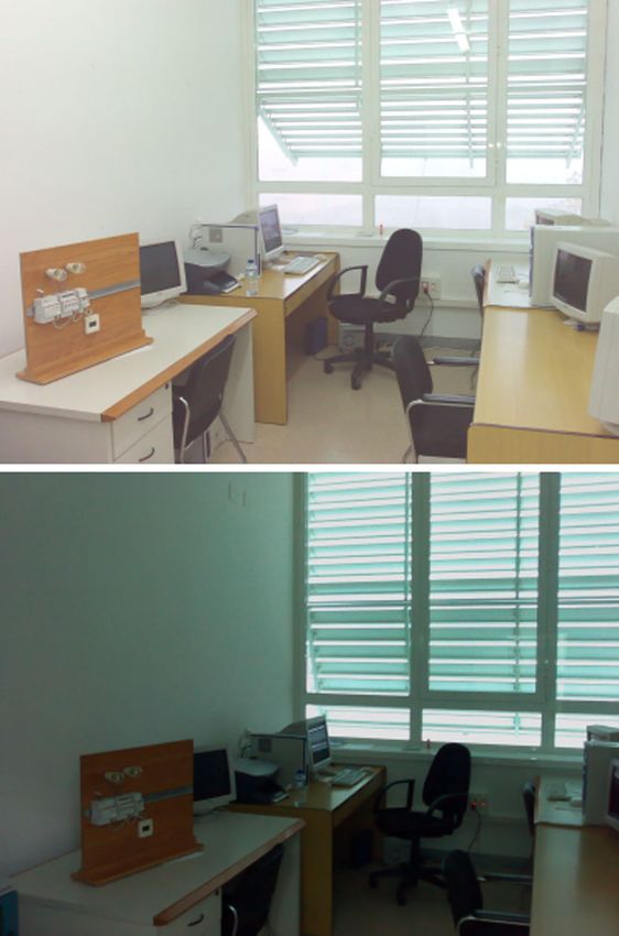
F. Chávez et al.

which implies using and interacting with a number of home          with Fuzzy Rule Based Systems (FRBSs) [19, 33, 34, 51,
devices. Developing accessible homes is thus of paramount          52] for trying to improve the success rate of images with
importance for this group. Recent research on smart homes          a laser spot, while also trying to completely avoid the false
[7, 14–16, 26, 28, 35, 40–42, 45] show the convenience of          offs of the previous systems. This kind of system allows easy
developing systems that integrate domotic systems for help-        adaptability to the problem at hand. With classic techniques
ing disabled and elderly people at home. Disabled people           the system only works with exact values, but this kind of sys-
can thus control their home appliances and other home de-          tems works with labels which allow the use of values similar
vices. Furthermore, they can be monitored by their family          to human language. With FRBS it is possible to quantify val-
when using this kind of system: information about their be-        ues as low, medium, high, similar, etc., this being the main
havior or dangerous situations that might arise can be sent        advantage of this kind of systems. This main characteristic
to family members.                                                 allows the derivation of a system from human experience,
    A complete review of Smart Homes is presented in [7,           representing an alternative when a good set of training data
26, 35] showing the great evolution of this technology in the      is not available (which is our case).
last few years. Smart homes integrate sets of sensors, cam-            With this new hybrid technique TM + FRBS, TM will
eras, computer based technologies, vision systems, IR sen-         be applied on complete images to extract a candidate image
sors and robots, which are at this moment too expensive for        section and the FRBS will determine whether the proposed
the end users. In [14], a robotic smart home is presented: a       section is a laser spot image or not.
disabled person is helped by a robot which picks up different          The FRBS presented in this paper has been designed by
objects previously indicated by the user by means of a laser       an expert, due to the particularly problematic conditions.
pointer.                                                           There is not enough information about the system to auto-
    The idea of using laser pointers for interaction pur-          matically learn the fuzzy rule set and the Membership Func-
poses is not new. They have been used for some time                tions (MFs) needed to correctly detect the laser spot. Conse-
now as an indicator element for interacting with large dis-        quently, it was developed thanks to expert knowledge of the
plays [29, 37, 39, 53]. In these works, the algorithms detect      problem. Results show the benefits of this technique, with
the laser spot in a controlled environment, with optimum           noticeable improvements in the success rate compared to the
light conditions, without reflections and inclinations with        previous systems.
the cameras focused on the large displays, but these situa-            This new system allows disabled people to have at their
tions are not applicable in a real home environment.               disposal a system with reduced cost because it will detect the
    In [14], the authors deal with this problem by using opti-     laser spot by software, without the need for special hardware
cal filters in special video cameras in charge of collecting en-   equipment or optical filters.
vironmental images, with the aim of easing detection of the            The system presented in this work can be used by dis-
laser spot. However, this is an on-going problem that can be       abled or elderly people, but we must to differentiate what
addressed by using laser spot detection algorithms based on        kind of people will adapt better to the system. Disabled peo-
the original non-filtered images, i.e. by using standard and       ple can be divided in 6 big groups, people with physical, sen-
non expensive cameras, without the necessary optical filters.      sory, cognitive or intellectual disability, people with mental
Furthermore, improving basic detection algorithms will also        or psychosocial illness and people with chronic illness. On
improve results regardless of the optical system employed.         the other hand, older people may have a degenerative dis-
This is the main contribution of this paper, to provide a new      ease, Alzheimer, sensory diseases, etc. It should be noted
laser spot detection system, which, in conjunction with a          that any person cited previously can have a limit or basic in-
standard domotic system, will enable a more friendly home          tellectual function, or intellectual function zero. Thanks to
environment.                                                       the simplicity of using the system, any disabled or elderly
    We addressed a similar problem when trying to improve          people with limited or basic intellectual function can use it.
domotic systems for disabled people. Some of our previous          On the other hand, physically disabled people could have
work [15] has analyzed a number of algorithms aimed at             some limit to use the system, but nowadays, there are a lot
detecting the laser spot effectively on the image obtained         of devices adapted to physical disabled people as mouses,
by a standard video camera. Nevertheless, the false offs de-       keyboards, screens even bikes, cars, etc. The system needs
tected are crucial problems to be fixed when interacting with      a laser pointer to indicate the device which could be eas-
home devices: when a false laser spot is detected by the al-       ily adapted for physically disabled people. Finally, although
gorithm an incorrect order is sent through the domotic sys-        this work is focused for people with disabilities, it can also
tem which could produce undesirable, dangerous or at least         be used as general purpose.
unexpected, situations.                                                This contribution is arranged as follows. In Sect. 2 the
    In this paper, we present a new approach to detect the         problem of using a laser pointer as a pointer device is de-
laser spot in the environmental device control system. It con-     scribed. The home environment control system and the pre-
sists of the combination of Template Matching (TM) [20]            vious algorithms applied to this problem are described in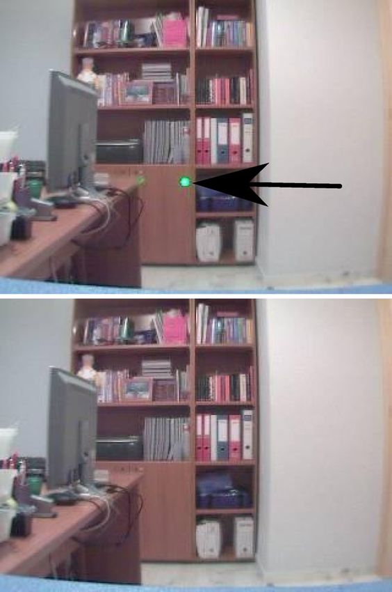
Hybrid laser pointer detection algorithm based on template matching and fuzzy rule-based systems

Sect. 3. The definition of the FRBS developed, as well as                the Homography technique, several video-cameras and sev-
its combination with TM, are presented in Sect. 4. The re-               eral computers are used in [3] to try to detect the correct
sults obtained by the proposed technique are analyzed and                laser spot position. In [29] a laser filter is used to improve
compared to the previous proposal in Sect. 5. Section 6                  the efficiency of the algorithm. Finally, in [11] and [39] a
makes some conclusions. Finally, Appendix shows the list                 set of images is analyzed and compared to try to eliminate
of acronyms used in this paper.                                          the false offs. We can observe that the laser spot is located
                                                                         not only by software, the Authors use special filter cameras,
                                                                         several computers, and other intrusive techniques for detect-
2 Laser pointer as a pointer device                                      ing the laser spot. Furthermore, in the most of the cases the
                                                                         algorithms work in controlled light environment conditions.
In this section a short review of the previous systems is pre-           In this setting, it is easier to locate the laser spot than in a
sented. Usually, these works present different uses of a laser           real home environment, where the brightness of light con-
pointer on a large display and on systems to help disabled               ditions are almost impossible to control, and the algorithms
people.                                                                  have to solve incontrollable situations.
    The papers presented in [3, 10–12, 18, 29, 30, 36, 37,                   Recent research has attempted to integrate a domotic sys-
39, 46, 50, 53] use a laser pointer as a pointing device on              tem in the home to help disabled and elderly people. These
large displays. The aim of these works is to be able to con-             are known as smart homes [7, 14–16, 26, 28, 35, 40–42].
trol the different objects presented on a large display. The             The most relevant work is found in [14], where a robot will
laser pointer was used in the same way as the mouse cursor.              pick up the object indicated by the user with a laser pointer.
Thanks to the laser pointer, users can interact directly with            This is a similar technique to the technique presented in this
objects projected on the screen.                                         paper, but the robot uses especial physical filters in the video
    Different techniques have been used for solving the prob-            camera for filtering the images and detecting the laser spot.
lem and detecting the laser spot, such as threshold value,                   Our main contribution in this paper is a new robust al-
pattern recognition, color analysis, etc. Kirstein and Müller            gorithm for effectively detecting a laser spot on an image,
used an algorithm divided into three phases for detecting the            together with a system to control the home devices selected
laser spot. The algorithm phases were, Motion Detection,                 by the user. The system presented removes the need for the
Pattern Recognition and Histograms Comparison [30]. By                   special equipments employed in the works referred to above,
means of these techniques, the laser spot is detected only on            such as camera filters, several video-cameras or other inva-
a 50% of the frames.                                                     sive techniques. Thanks to the new system presented in this
    The works presented in [3, 11, 12, 18, 32, 37, 39, 53]               paper, disabled and elderly people have at their disposal a
used an algorithm only based on threshold value. These al-               system with which they will be able to control the different
gorithms can classify the brightest pixels using a thresh-               home devices easily with a laser pointer cheaper than those
old value calculated previously. This set of classified pix-             previously presented.
els could be the laser spot pixels. But these algorithms have
similar results to the algorithm referred to above.
    A different technique for detecting the laser spot is pre-           3 Preliminaries: system description and starting point
sented in [29]. This algorithm uses different color systems,
such as Red, Green and Blue (RGB) and Hue, Saturation                    The environment device control system by a laser pointer
and Intensity (HSI) systems, for detecting the laser spot on             for disabled and elderly people is described in-depth in this
an image. A video-camera takes a color image in the RGB                  section. Furthermore, the previous techniques applied to this
system. The algorithm changes the color system to the HSI                particular system [15] are also described as the starting point
system. By means of a segmented function, the laser spot is              on which we should improve. These techniques are:
detected.
    The main problem in these previous works is that light               – Dynamic Umbralization (DU).
conditions, inclinations and textures are controlled and                 – TM.
fixed. For example, the laser spot can not be detected cor-              – TM plus DU.
rectly with high brightness light on the displays.
    On the other hand, since the previous approaches typi-               3.1 System description
cally present many false offs, special cams including optical
filters have also been used. In [18] the authors used wave-              The system is divided in three sections, Family Tool Section,
length bandpass filters together with several video-cameras              Algorithms Analyzer and Domotic Control System. Figure 1
for detecting the laser spot. In [12] and [53] a red filter is ap-       shows the different system sections. In the following subsec-
plied to the video-camera to try to solve the false off. With            tions we describe in detail each system section.
F. Chávez et al.

                                                                   the position of the laser spot. By means of the laser pointer
                                                                   the user selects the device he wants to use. The laser pointer
                                                                   makes a red or green spot on the device. The video camera
                                                                   sends the environmental image with the laser spot informa-
                                                                   tion and the computer analyzes this image and locates the
                                                                   laser spot. If the laser spot is on an active zone, the user
                                                                   wants to use the device marked in this zone, and finally, the
                                                                   computer sends the necessary orders to turn on/off this de-
                                                                   vice using the domotic system.
                                                                      The video camera used by the system is an Axis 207W
                                                                   video camera. This camera has 1.3 Megapixels with an im-
                                                                   age sensor of 1/3 Micron progressive RGB CMOS, lens
                                                                   dimensions of 3.6 mm/F1.8 and 2–10000 (Lux). The laser
                                                                   pointer used is a green laser pointer class III with maximum
Fig. 1 Environment control system
                                                                   power < 5 mW and wave length of 532 nm.
                                                                      In some of our previous works, a number of algorithms
                                                                   aiming at detecting the laser spot on the images sent by the
3.1.1 Family tool                                                  camera were employed and analyzed [15]. These algorithms
                                                                   are presented in the following section.
The first action to use the system must be carried out by
Family members or Teachers. They have to indicate where            3.1.3 Domotic control system
the devices are, which will be handled by the domotic sys-
tem. For this, there is an especial software tool for the family
                                                                   The third section of the system deals with the devices con-
members. By means of this tool, a fixed video camera in an
                                                                   trolled by the domotic system using KNX/EIB architecture
home environment takes an image and sends to the com-
                                                                   [22]. Once the laser spot is found and it is in an active zone,
puter. This image is shown in a tool and the user (family
                                                                   the system sends different orders to turn on/off the device
member or teacher) marks, by using a simple click method,
                                                                   associated with this active zone, to the domotic system. But
the devices that will be handled by the domotic system. The
                                                                   the system can be configurated to do more complex actions.
subsequent marked image is known as an “active zone”.
                                                                   Depending of the final user, the complex functions of the
Therefore, an active zone is a set of pixels which contains in-
                                                                   home devices can be encoded differently. For instance, if
formation on the positioning of the devices. Previously, the
                                                                   the final user is a person with physical disability, a panel
domotic system must be configurated by an expert, whom
                                                                   close to the device to handle will be put. This panel could
will indicate how many home devices will be handled and
the type of each device. When the active zone has been             have four sections, Volume, Channel, + and −, indicating
marked, the user must select a device of the list of devices       the user the complex action for the TV on the panel. Other
previously defined by domotic system expert. Whit this ac-         possibility could be including different active areas on a sin-
tion, the active zone will be matched with the home device         gle device, thus allowing largest set of actions. However, if
and the system has information on the positioning of this          the final user has best skill, the system could analyze ges-
device.                                                            tures users, tracking the laser pointer.
    Once the actives zones have been marked, a disabled or
elderly person can indicate what device he/she wants to use        3.2 Algorithms and methods based on dynamic
by a laser pointer. The system will analyze the actives zones          umbralization and template matching
previously indicated, and if on an active zone the laser spot
is found, the domotic system will handle the home device           The algorithm DU is the first algorithm used. This algorithm
associated.                                                        is based on umbralization [44], and tries to find high energy
    Finally, if a home device or camera is changed within a        pixels generated by a laser spot within the image. The sec-
given environment then the active zones must be recreated          ond algorithm used was TM [13]. This algorithm is used to
so that they are updated by the system.                            find a laser template—previously calculated—on the image.
                                                                   Finally, we use a new joint process algorithm which joins
3.1.2 Algorithms analyzer                                          both previous algorithms, TM and DU. Using this new algo-
                                                                   rithm we have achieved a more stable environment control
The second section of the system is the algorithm which will       system for disabled people by using a laser pointer [15]. In
analyze the images sent by the fixed video camera and locate       the following section, these techniques are presented.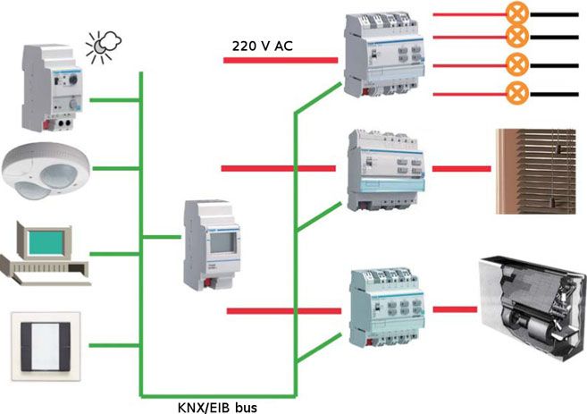
Hybrid laser pointer detection algorithm based on template matching and fuzzy rule-based systems
3.2.1 Dynamic umbralization Table 1 Sub intervals balance
Level Balance
DU algorithm is based on umbralization [44], which is a
technique frequently used to locate information on an image Low (0%–33%) 0
using a threshold value. Middle (33%–66%) 1
This technique calculates a value known as a threshold High (66%–100%) 2
value. This value is used to eliminate the image information
over or under it. With this technique, the relevant informa-
Table 2 Parameters balance
tion of an image can be separated, that is, the laser spot in-
formation. Parameter Balance
The steps we took in the procedure are the following. We
analyzed a set of images with and without laser spot pix- % largest value of the histogram 4 ∗ sub interval balancea
els, and discovered that the laser spot pixels have their own Largest value of the histogram 3 ∗ sub interval balancea
characteristic information. These pixels, as we discovered, Average 2 ∗ sub interval balancea
have lower numerical information, due to high energy. We Sum 1 ∗ sub interval balancea
used a static threshold value which could eliminate all pix-
a The sub interval balance is obtained by applying the criteria in Table 1
els without laser spot information. The results were positive;
for each parameter
the algorithm could locate the laser spot on the image. The
next step was to change the light conditions. Depending on
different light conditions the threshold value calculated was Once the interval parameters have been obtained, we
not the ideal. Therefore, we calculated a dynamic threshold must take the smallest interval (Imin ) and the largest inter-
value using four parameters extracted from the image. The val (Imax ) previously calculated. With these two numbers we
parameters taken from the histogram included the largest can obtain the rate of umbralization as we can see in Table 3.
value, a percentage of the largest value and the average and The final threshold value is calculated by applying the
the sum of the pixel numerical information, thereby giving following expression.
us a more dynamic umbralization. With these parameters we
X
could calculate a different threshold for each image sent by Vumb = ((Sv_Imax ) − (Sv_Imin )) ∗ + (Sv_Imin ) (2)
20
the video camera.
For a more precise evaluation we divided the parameter Where X is the sum of the balance parameters obtained
values from the smallest and largest values in six intervals when applying Table 2, Sv_Imin is the lowest value of Imin
represented in [15]. interval corresponding to Table 3 and Sv_Imax is the highest
The first step is to calculate the histogram. This histogram value of Imin interval corresponding to the same table.
is calculated using a color environmental image sent by the The threshold value is calculated for each image sent by
video camera. For each pixel, the algorithm takes the inte- the video camera. With this operation the threshold value
ger value of the pixel and this value is divided by 256. The changes in real time, depending on the light conditions.
histogram is represented by a vector with 256 positions. The The DU algorithm eliminates all pixels under the Vumb
vector position corresponding to the remainder calculated in calculated. The pixels which have not been eliminated are
the previous division is incremented by one, so it generates the laser spot pixels.
the histogram of the image. To measure the effectiveness of the algorithm used in
The next step is to calculate the percentage of the largest DU we performed several experiments using the algorithms
value histogram intervals [15] by using the following ex- [15]. We used two kinds of laboratory controlled environ-
pression: ments, one with optimum light conditions using normal-low
largest value ∗ 100 light, and another with non-optimum light conditions using
percentage = (1) intense light. In the second condition, there are many reflec-
weightimage ∗ heightimage
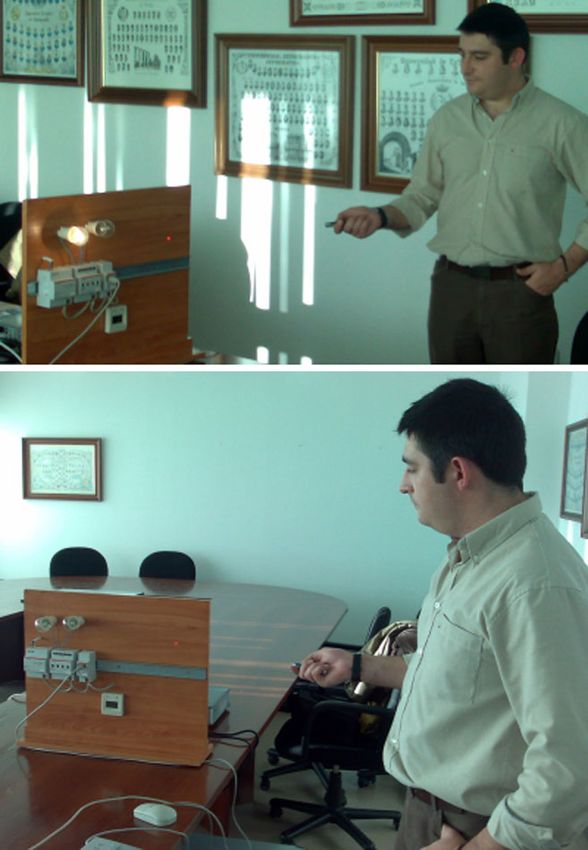
tions which the system interprets as pixels with high energy,
Once the intervals where the different parameters are as if they were laser spot references. Figure 2 shows the op-
were calculated, we divided the intervals into three different timum and non-optimum light conditions.
sub intervals and checked where each parameter value was In non-optimum light conditions and in images with re-
within these three sub intervals. In order to find where the flections, the DU algorithm had false offs. Figure 3 shows
parameter value was within the sub intervals, we established an example of a laser spot and a false off located.
Table 1. Trying to eliminate the false off we used the TM tech-
The parameter values are of varying importance within nique. Instead of analyzing the pixel information, this tech-
the dynamic umbralization calculation. The importance of nique tries to find a template laser, previously calculated, on
this is shown in Table 2. the image sent by the video camera.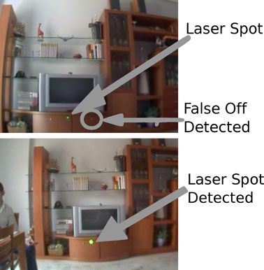
F. Chávez et al.

Table 3 Umbralization
intervals                       Interval 0       Interval 1      Interval 2           Interval 3              Interval 4        Interval 5

                                0                2 ∗ 106         4 ∗ 106              6 ∗ 106                 8 ∗ 106           10 ∗ 106
                                2 ∗ 106          4 ∗ 106         6 ∗ 106              8 ∗ 106                 10 ∗ 106          12 ∗ 106

                                                               Fig. 3 Success and false off using the DU algorithm

                                                               Fig. 4 Template laser spot

                                                               between −1 and 1 [20] and [38]. The expression is as fol-
                                                               lows:

                                                                                        i,j ∈[−w,w] AB
                                                               (Ir , Il ) =
                                                                                               2                 2
                                                                                i,j ∈[−w,w] A      i,j ∈[−w,w] B
Fig. 2 Light conditions                                                                                              (3)
                                                               A = Ir (x + i, y + j ) − Ir (x, y)

                                                               B = Il (x  + i, y  + j ) − Il (x  , y  )
3.2.2 Template matching
                                                               where the expression part known as A contains the set of
                                                               pixels which are in the principal image section, and the
This technique is based on locating a template which is on
                                                               section known as B contains the set of laser template pix-
an image. This algorithm analyzes small image sections that
                                                               els.
are compared with the template which it wants to find. In         In order to use this technique, a set of templates must be
this operation the correlation between the image section and   previously calculated. The algorithm to calculate the set of
the template is calculated. Using the pattern search tech-     templates is divided in two sections:
nique [44] the algorithm can find a template for the whole
image. Figure 4 shows a template laser used by the algo-       1. Section 1: The algorithm takes 30 images of a laser spot
                                                                  on a white surface.
rithm.
                                                               2. Section 2: The algorithm calculates an average image
    The kind of measure used to calculate the correlation
                                                                  with the images previously taken.
values between the template and the image is known as
Zero Mean Normalized Cross Correlation (ZMNCC). The              To calculate the set of templates it is necessary a video
value obtained with this kind of correlation is normalized     camera fixed in a specific location and focused on a white
Hybrid laser pointer detection algorithm based on template matching and fuzzy rule-based systems

surface. A laser spot is then drawn on this surface with a
laser pointer. A snapshot image is then taken every 0.5 sec-
onds, ending with a total of 30 images. With these 30 images
the system calculates an average image in the second step.
With the average image we eliminate the CCD noise of the
video camera. This average image is the resulting template.
This process is carried out between 2 and 5 meters from the
video camera to the surface and with different light condi-
tions. Once the process has finished, we obtain the set of
templates used by TM algorithm to search the laser spot in
the images sent by the video camera.
    The TM algorithm consists on a process to calculate the
correlation value between a section of the image sent by the             Fig. 5 Success and false off using the TM technique
video camera with a similar size to the templates used. The
system uses different templates depending on the environ-
mental conditions. There are two parameters to chose the
correct template, the distance and the light condition. The
distance between the video camera and the home devices is
known by the system, because for each zone, the user has to
indicate the distance between the camera and the home de-
vices. On the other hand, the lights conditions depend on the
system operating hours and the a luminance image analysis.
    Using the expression (3) the TM algorithm obtains the
correlation between an image section and the template used.
The expression part known as A contains the set of pixels
which are in the principal image section, and the section
known as B contains the set of laser template pixels. With
both sets of pixels the correlation value is calculated and
saved in a vector together with the coordinates which ap-
pear in the center of the main image section. Using a convo-
lution technique the algorithm can analyze the whole image
sent by the video camera. Finally, all correlation values are            Fig. 6 Description of TM + DU
saved in a vector together with the analyzed image coordi-
nates, thereafter it extracts the highest value. Generally, the
template which is searched for can be found in the coordi-               zone it searches a template and obtains a maximum corre-
nates which have the highest values.                                     lation value. A section of the active zone of 15 × 15 pixels
    With this new improvement we eliminate DU false offs,                is taken where the highest correlation value was found. This
thereafter obtaining better results than when using the pre-             section has a similar size to the template used. In this new
vious algorithm.                                                         image the laser spot could be found, being necessary that it
    TM obtains better results than DU, however the new al-               has high energy output. In the following step we use DU to
gorithm now has new false offs [15]. This is due to the fact             check these pixels. If they have high energy, we can say that
that it may interpret small component devices like buttons,              the laser spot can be found here, because this section is very
LEDs, circular reflections on devices, etc., as laser spots. An          similar to a template. The process is shown in Fig. 6.
example of a false off obtained with TM algorithm can seen                   The results of this new approximation are presented in
in Fig. 5.                                                               Sect. 5.
    To eliminate false offs in both algorithms we developed
a new algorithm to join the two techniques.
                                                                         4 Fuzzy rule based system for the domotic system
3.2.3 Combining template matching & dynamic
      umbralization techniques                                           In Sect. 3 the previous algorithms used classic techniques to
                                                                         detect the laser spot. The false offs of this system indicate
This method combines the advantages of TM and DU. This                   to us that these algorithms have to improve. If the algorithm
algorithm analyzes only the active zones. For each active                has several false offs, a dangerous and uncontrollable situa-
F. Chávez et al.

                                                                            The most interesting characteristic is that the laser spot
                                                                        pixels should present high energy in any image. The pixel
                                                                        values of a laser spot in an RGB system are approximately
                                                                        [255, 255, 255]. Moreover, we can observe that a laser spot
                                                                        is similar to a circle. These two properties have been con-
                                                                        sidered by the expert as the most important properties of a
                                                                        laser spot image. Taking these characteristics as the starting
                                                                        point, we have to obtain a number of variables which can
                                                                        describe the characteristics of the laser spot on an image for
                                                                        detecting it correctly.
                                                                            In the next section, we describe the definition of these
                                                                        variables as a part of the evolution of the FRBS developed by
                                                                        the expert, from the initial FRBS to the final FRBS proposed
                                                                        in this paper.
                                                                        1. FRBSinit : Initial FRBS which uses 6 variables to detect
                                                                           the laser spot (five inputs and one output).
                                                                        2. FRBStuned : Final FRBS which uses 6 variables to detect
                                                                           the laser spot where the MFs have been tuned to improve
                                                                           the results (five inputs and one output).
                                                                           The fuzzy rule set for each of these two systems com-
                                                                        prised of the following type of rules:

                                                                        if X1 is A1 and . . . and Xn is An THEN Y is B

                                                                        where Xi (Y ) are the input (output) linguistic variables,
                                                                        Ai (B) are the linguistic labels used in the input (output)
                                                                        variables.
                                                                           The fuzzy inference system uses the center of gravity
                                                                        weighted by the matching strategy as a defuzzification oper-
Fig. 7 Image with laser spot (top), Image without laser spot (bottom)
                                                                        ator and the minimum t-norm as implication and conjunctive
                                                                        operators [17].
tion may arise, because an incorrect order will be sent to the             More complete information on the inference process of
domotic control system.                                                 FRBSs can be found in [8, 19] and [47], where FBRSs are
   The main aim of this work is to design and develop a                 explained in detail. The FRBS presented in this paper uses
system which will try to avoid the false offs of the previous           Mamdani-type rules and as it can be seen from the previous
systems and to increase the general success rate. The prob-             description the defuzzification method is based in mode B:
lem in detecting a laser spot on an image is that we do not             Defuzzification First, Aggregation After. An example of this
have enough data to learn it automatically. For this reason,            kind of fuzzy inference system is shown in [4–6] and [21]
we have considered an FRBS [19, 33, 34, 51, 52]. The pro-               for the control of a Heating, Ventilating and Air Condition-
posed FRBS rules will be designed by an expert since in this            ing System. FRBSs are used in processes such as, industrial
case the expert knowledge will be beneficial to the system.             control [49], robotics control [2] or control in communica-
                                                                        tions [9].
4.1 Methodology based on FBRSs
                                                                        4.1.1 An initial FRBS (FRBSinit )
The first step is to obtain a set of variables, which will be ex-
tracted by analyzing a set of images, with and without laser            FRBSinit uses the following 6 variables to try to detect the
spots. Thanks to an expert experience and a complete study              correct laser spot,
of the histograms of laser spots and non laser spots images,            – X1 : bell amplitude near the 255 value in the image his-
the expert can determinate the correct set of characteristics             togram.
which can differentiate images with laser spot and images               – X2 : bell height previously calculated.
without laser spot. In Fig. 7, an example of images with and            – X3 : Long standard deviation.
without a laser spot is presented.                                      – X4 : Cross standard deviation.
Hybrid laser pointer detection algorithm based on template matching and fuzzy rule-based systems

                                                                         Fig. 9 Laser spot (top). High and long standard deviation (bottom left).
                                                                         Cross circle standard deviation (bottom right)

                                                                            The algorithm explained previously extracts 5 variables
Fig. 8 Laser spot image histogram                                        which represent the characteristics of a laser spot image.
                                                                         With these 5 variables, the FRBS will try to determinate if
                                                                         the images analyzed are laser spot images or not.
– X5 : Similarity to perfect circle value.
– Y : Laser spot probability.
                                                                         4.1.2 Final FRBS (FRBStuned )
   Figure 8 shows a typical laser spot image histogram. If
the laser spot image histogram is analyzed, we can observe               Once the FRBSinit was developed the results indicated that
that there is a set of pixels which indicates that the image             the system could be improved. In the next approximation,
has a section with high energy pixels, the pixels close to the           the algorithm to eliminate non-laser pixels was adjusted and
255 value.                                                               improved. A new variable was added, laser spot number of
   Every FRBS referred to above uses a previous algorithm                pixels. This variable stores the number of candidate laser
to extract the variable’s values. The algorithm calculates the           pixels. Finally, the bell amplitude near the 255 value in the
amplitude of the bell corresponding with the pixel near to the           image histogram and the previously calculated bell height
255 value of the histogram, and its height (variables X1 and             variables are eliminated from the system.
X2 ). With X1 variable can be determined if there are some                  A new adjustment to the algorithm to eliminate non-laser
pixels in 255 value in the histogram. With X2 variable can               pixels was made. In this new adjustment we used the per-
be determinated how many pixels there are close to the 255               centile 80 of the histogram distribution. With this value, the
value in the histogram. These variables are very important               algorithm can eliminate all pixels of the histogram distribu-
to determinate if there are pixels with high energy.                     tion with low energy, and only pixels with high energy will
   In the next step, the algorithm tries to eliminate all non-           not be eliminated, independently of whether this set of pix-
laser pixels in the image. Once the non-laser pixels have                els is close to the 255 value in the histogram. We observed
been eliminated, the image only has a set of candidate laser             that the value of percentile 80 is an important variable for
pixels. This set of pixels should be similar to a circle. In or-         the FRBS; for this reason, in the next approximation it is
der to take this fact into account, the values for the next two          added as a new variable.
input variables, long and cross standard deviation, are cal-                Finally, in the final FRBS (FRBStuned ) designed by the
culated (variables X3 and X4 ). Figure 9 shows the laser spot            expert, the MFs corresponding with the variables X3 and X5
standard deviations obtained. To obtain the standard devi-               are changed to triangular MFs and are newly adjusted by the
ation values, the diameters shown in Fig. 9 have to be ob-               expert. The results show that with the percentile 80 variable,
tained. Once, the diameters are obtained, the standard devi-
                                                                         together with this new adjustment in the triangular MFs, we
ations are calculated.
                                                                         have developed a robust FRBS to detect a laser spot on an
   Finally, the similarity to a perfect circle is calculated.
                                                                         image.
For this, an image with a perfect circle is generated. Using
                                                                            The set of variables in FRBStuned are:
the TM technique (see expression (3)), the main image and
the image generated are compared. The correlation between                 –   X1 : Long standard deviation.
these images is the similarity to a perfect circle (variable              –   X2 : Cross standard deviation.
X5 ), which also represents an input variable.                            –   X3 : Similarity to perfect circle value.
   The variables X3 , X4 and X5 indicate if the candidates                –   X4 : Laser spot number of pixels.
laser pixel are similar to a circle, the second characteristic            –   X5 : Percentile 80 value.
of a laser spot image.                                                    –   Y : Laser spot probability.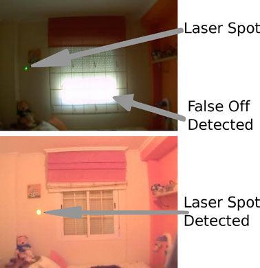
F. Chávez et al.

Fig. 10 Definition of the FRBStuned MFs

Where the variables X1 , X2 and X3 indicate us if the pix-
els no eliminated are similar to a circle. The variable X5
indicates us where pixels will be considered as pixel with
high energy, independently if these pixels are close to 255
value. We observed that depending on light conditions, the
pixels with high energy could be close to 255 or not. Finally,
the variable X4 indicates us how many pixels have not been       Fig. 11 Images with laser spot
eliminated. With this information it is possible to determi-
nate if the image analyzed is a false offs when there are few
pixels no eliminated.                                            4.3 Application of the FRBS in the domotic system

4.2 Final membership functions and rule base                     In order to apply the obtained FRBSs (init and tuned) in the
                                                                 laser spot recognition task, it is combined with TM, giving
Once the FRBStuned input variables have been determined,         way to a new hybrid technique, TM + FRBS. The first al-
the next step is to design the FRBStuned MFs. The FRBStuned      gorithm, TM, analyzes the image sent by the video camera
MFs have been designed by an expert thanks to his system         together with a template image. This obtains the image sec-
knowledge and experience. Once the MFs were designed,            tion with the highest correlation. To do this, this technique
they were tuned by hand by an expert in order to obtain use-     makes use of a precision coefficient. If the ZMNCC value
ful definitions. Figure 10 shows the associated intervals and    between the image section that is being analyzed and the
the MF definitions.                                              template image used is equal to or higher than this precision
   Once the input variables and their domains have been de-      value, this section image will be stored in the correlation
fined, the expert can define useful rules for the detection      vector. Once the main image has been completely analyzed,
task.                                                            the algorithm takes the image section with the highest corre-
   Table 4 shows the set of rules determined by the expert       lation saved in the vector. Thus, the image section with the
using the linguistic concepts defined for each variable.         highest probability of being a laser spot is obtained.
   In this work, the membership and rules have been ob-              In Figs. 11 and 12 we can see an example of images’
tained from human experience. Once the initial FRBS was          sections extracted by the TM technique.
developed, this system was improved to obtain a new FRBS,            This image section is analyzed using FRBSinit or
applying again the human experience. The membership              FRBStuned . The output FRBS value will indicate whether the
functions and rules were initially tuned by hand by the ex-      image analyzed is a laser spot image. This decision is taken
pert.                                                            by a threshold value known as umbral (U ). If the inferred
Hybrid laser pointer detection algorithm based on template matching and fuzzy rule-based systems
Table 4 Fuzzy set of rules
Rule X1 : Long standard X2 : Cross standard X3 : Similarity to X4 : Laser spot X5 : Percentile 80 Y : Laser spot
deviation deviation perfect circle number of pixels probability
1 Regular Regular No-similar Medium Low
2 Regular Regular Similar Medium High
3 Regular Regular Semi-similar Medium High
4 Irregular Irregular No-similar Medium Low
5 Irregular Irregular Semi-similar Medium Low
6 Irregular Irregular Similar Medium Medium
7 No-similar Medium Low
8 Semi-similar Medium Low
9 Irregular Regular Medium Low
10 Regular Irregular Medium Low
11 High Medium Low
12 Regular Regular Semi-similar Medium Medium Medium
13 Low Low
14 High High
that make up the database were taken trying to simulate the
final user actions different conditions:
– Light conditions: normal light, bright light and artificial
light.
– Distance: distance between the laser pointer and the area
where the device is placed. This distance is between 2 and
Fig. 12 Images without laser spot
5 meters.
Every system presented in this paper uses a TM algorithm
value is higher than this U value, the system considers that
the image analyzed is a laser spot image. By contrast, the to obtain an image section candidate which could have the
system will consider that the image analyzed is a non laser laser spot looked for. An image template previously calcu-
spot image, if the inferred value is under U . This new com- lated, using the technique shown in Sect. 3.2.2, is used to
bination of algorithms directly presents a better performance compare the image sent by the video camera with this tem-
than the algorithms described in Sect. 3.2. The correspond- plate image, and thus, to extract the image section with the
ing results will be shown in the next section. highest correlation using the TM algorithm. To extract this
section, TM uses the most appropriate template, indicated
by the expert, to look for the laser spot on an image. This
5 Framework and experimental study process is used for both training and test set of images.
TM uses a precision coefficient to select as a candidate
This section is divided into three different parts. The first the image section that is being analyzed by the main image.
part shows the framework where the different models are We have considered the following two values for our study:
used on a domotic control system. Then, the results obtained 0.3 and 0.5.
by the proposed technique are shown in two subsections On the other hand, the performance of the TM + FRBS
where TM + DU [15], TM + FRBSinit and TM + FRBStuned system has been calculated. The system can analyze 8 im-
are analyzed and compared. ages per second. It must be aware that the system is se-
To evaluate the different systems and for assessing the quential and it is in the development phase using MatLab
quality of them, we were provided with a large set of images, software tools. Once the system will be parallelized, it will
with 210 real home environment images (see an example in analyze a enough set of image for working in real-time.
Fig. 7). This set of images has been divided in a training set In the following, we describe the framework where the
of 105 images used during the learning process and a set of hybrid laser pointer detection algorithm is integrated in the
105 images used to test the quality of the system. The images domotic control system for real home environments. Then,F. Chávez et al.
Fig. 13 KNX/EIB bus
we show the experimental results and an analysis of the stud-
ied techniques.
5.1 Framework: domotic control used by the environment
control system
In this section we describe the framework of the domotic
control system where the TM + FRBS system is integrated
to detect the laser spot on an image and to control the home
device selected by the user. This system is endowed with
KNX/EIB architecture [22] by means of the laser pointer.
Our software tool has been easily combined with KNX/EIB
control software, such as ETS software [31]. Fig. 14 Domotic panel
KNX technology is an open standard for all applica-
tions in home and building control. KNX technology is a USB interface and the KNX/EIB bus. The power supply
composed of BATIBUS, EIB y EHS, the base of KNX is is used to feed the various domotic components. The power
EIB (European Installation Bus). KNX/EIB is the first Eu- supplies are essential for a specific, robust and efficient com-
ropean standard (EN50090 and EN 13321-1) [43] interna- munication bus. The switch device allows us to connect the
tional standard (ISO/IEC 14543-3) [25] and Chinese Stan- different home devices which will be turned on/off by it.
dard (GB/Z 20965). This technology is used to control secu- Finally, the USB interface enables communication between
rity systems, heating, ventilation, air conditioning, monitor- the PC and the KNX/EIB installation. The USB interface is
ing, alarming, water control, energy management, metering simply connected to the KNX/EIB bus and then connected
as well as household appliances, audio [27]. to the PC. The USB interface is automatically detected by
KNX/EIB is a multimedia protocol with which it is pos- the PC operating system and installed. Figure 14 shows the
sible to send signals by a cable (BUS). The signals can be domotic panel that we use to simulate a real home environ-
Power Line, RF, IR, Bluetooth, and this protocol accepts the ment. The system sends the information by a USB cable
Ethernet protocol. This signal can be sent by a PC, domotic which allows us to turn on/off the devices selected by the
devices or home devices such as switches. A configuration handicapped person, using the laser pointer.
of a system is presented in Fig. 13. The whole system allows the users to indicate the active
The TM + FRBS algorithm, which allows us to know the zones and the home devices to control, by means of the fam-
position of the laser spot and the device that the user wants ily tool. In the second step, by using a laser pointer, a dis-
to use, combined with a Linux based KNX/EIB domotic sys- abled or elderly person can indicate the environment device
tem developed by Werntges [48] has enabled us to obtain a which he wants to use. Thanks to the KNX/EIB domotic
whole system allowing us to send orders to devices selected system, the computer can send the necessary orders to turn
by users by means of the laser pointer. on/off the device selected by the user to the domotic panel.
We have used a KNX/EIB domotic system for experi- Finally, with the aid of this kind of system, many disabled
ments. It is composed of a power supply, a switch device, people could lead an almost normal life, in spite of theirHybrid laser pointer detection algorithm based on template matching and fuzzy rule-based systems
Table 5 TM and DU system results
System Precision of ZMNCC Success rate in Success rate in image Success rate in image
in TM algorithm general with laser spot without laser spot
Training Test Training Test Training Test
TM + UD 0.3 76.19% 77.14% 63.08% 60.38% 97.50% 94.23%
TM + UD 0.5 75.24% 77.14% 61.54% 60.38% 97.50% 94.23%
Table 6 TM + FRBSinit using images sections obtained with a ZMNCC coefficient value of 0.3
System Precision of ZMNCC U Success rate in Success rate in images Success rate in images
in TM algorithm general with laser spot without laser spot
Training Test Training Test Training Test
TM + UD 0.3 76.19% 77.14% 63.08% 60.38% 97.50% 94.23%
TM + FRBSinit 0.3 0.3 68.57% 53.33% 100.00% 94.34% 17.50% 11.54%
TM + FRBSinit 0.3 0.4 69.52% 58.10% 96.92% 94.34% 25.00% 21.15%
TM + FRBSinit 0.3 0.5 67.62% 71.43% 80.00% 86.79% 47.50% 55.77%
TM + FRBSinit 0.3 0.6 69.52% 73.33% 70.77% 75.47% 67.50% 71.15%
TM + FRBSinit 0.3 0.7 73.33% 73.33% 66.15% 58.49% 85.00% 88.46%
disability. These kinds of systems allow disabled people to that the system has been well designed because the results
integrate both socially and professionally, giving them the using the test set of images is similar. Obtaining a success
ability to enjoy a life as normal and complete as possible; rate in general of 73.33% and in images without laser spots
as the international law on the Rights of Disabled Persons of 88.46%, with a defuzzification value over the U value of
states is their right [1]. 0.7 in both test.
The TM + FRBSinit has better results using training set of
5.2 Results obtained by TM + FRBSinit images and these results are very similar if the system uses
the test set of images. But the TM + DU has better results
In this section the results of TM + FRBSinit are presented. than TM + FRBSinit . We can see that the TM + FRBSinit sys-
To compare the initial FRBS developed by the expert versus tem has worse results in images without laser spot, however,
the previous TM + DU system designed [15], this system the system has better results in images with laser spot. For
applies the DU algorithm for each image of the set of image this, FRBSinit must be tuned to obtain the best results.
sections obtained using the ZMNCC coefficient value with
0.3 and 0.5 respectively. The success rates of the TM + DU 5.3 Results obtained by TM + FRBStuned
system are shown in Table 5.
The results shown in Tables 6 and 7 use FRBSinit with In this section the results of TM + FRBStuned are presented
umbral U between 0.3 and 0.7. This results have been ob- to compare the final FRBS developed by the expert versus
tained using the training and test set of images. the previous TM + DU system designed.
We can see that the TM + FRBSinit system has a general The results are shown in Tables 8 and 9 with ZMNCC
success rate of 73.33% and a success rate in images without coefficients of 0.3 and 0.5, respectively, and using FRBSinit
laser spots of 85.00%, using the training set of image sec- with an Umbral (U ) between 0.3 and 0.7. These results have
tions obtained with a ZMNCC coefficient value of 0.3. If the been obtained using the training and test set of images.
system uses the test set of images, we can see that the system Once the FRBS is adjusted and the percentile 80 as a new
has similar results, a general success rate of 73.33% and a variable is introduced, we can observe in Tables 8 and 9 that
success rate in images without laser spots of 88.46%. These the system has a good success rate using the training and
results have been obtained with a defuzzification value over test set of images. If the FRBStuned uses ZMNCC precision
the U value of 0.7 in training and test. On the other hand, to 0.3, the system has its best success rate if the defuzzifi-
if the FRBSinit uses the image sections obtained with a ZM- cation value is over a U value of 0.6. With this FRBS ad-
NCC coefficient value of 0.5, the system has the best success justed by the expert, the general success rate of the system
rate of 73.33% and a success rate in images without laser is 80.00%, the success rate in images without laser spots is
spots of 90.00%, using the training set of images. We can see 97.50%, and the success rate in images with a laser spot isF. Chávez et al.
Table 7 TM + FRBSinit using images sections obtained with a ZMNCC coefficient value of 0.5
System Precision of ZMNCC U Success rate in Success rate in images Success rate in images
in TM algorithm general with laser spot without laser spot
Training Test Training Test Training Test
TM + UD 0.5 75.24% 77.14% 61.54% 60.38% 97.50% 94.23%
TM + FRBSinit 0.5 0.3 74.29% 58.10% 92.31% 90.57% 45.00% 25.00%
TM + FRBSinit 0.5 0.4 75.24% 62.86% 90.77% 90.57% 50.00% 34.62%
TM + FRBSinit 0.5 0.5 73.33% 73.33% 76.92% 83.02% 67.50% 63.46%
TM + FRBSinit 0.5 0.6 73.33% 73.33% 67.69% 75.47% 82.50% 71.15%
TM + FRBSinit 0.5 0.7 73.33% 73.33% 63.08% 58.49% 90.00% 88.46%
Table 8 TM + FRBStuned using images sections obtained with a ZMNCC coefficient value of 0.3
System Precision of ZMNCC U Success rate in Success rate in images Success rate in images
in TM algorithm general with laser spot without laser spot
Training Test Training Test Training Test
TM + UD 0.3 76.19% 77.14% 63.08% 60.38% 97.50% 94.23%
TM + FRBStuned 0.3 0.3 73.33% 74.29% 78.46% 90.57% 65.00% 57.69%
TM + FRBStuned 0.3 0.4 75.24% 73.33% 78.46% 88.68% 70.00% 57.69%
TM + FRBStuned 0.3 0.5 77.14% 75.24% 76.92% 77.36% 77.50% 73.08%
TM + FRBStuned 0.3 0.6 80.00% 79.05% 69.23% 64.15% 97.50% 94.23%
TM + FRBStuned 0.3 0.7 80.00% 79.05% 69.23% 64.15% 97.50% 94.23%
Table 9 TM + FRBStuned using images sections obtained with a ZMNCC coefficient value of 0.5
System Precision of ZMNCC U Success rate in Success rate in images Success rate in images
in TM algorithm general with laser spot without laser spot
Training Test Training Test Training Test
TM + UD 0.5 75.24% 77.14% 61.54% 60.38% 97.50% 94.23%
TM + FRBStuned 0.5 0.3 75.24% 76.19% 76.92% 88.68% 72.50% 63.46%
TM + FRBStuned 0.5 0.4 77.14% 75.24% 76.92% 86.79% 77.50% 63.46%
TM + FRBStuned 0.5 0.5 79.05% 77.14% 75.38% 75.47% 85.00% 78.85%
TM + FRBStuned 0.5 0.6 79.05% 80.00% 67.69% 64.15% 97.50% 96.15%
TM + FRBStuned 0.5 0.7 79.05% 80.00% 67.69% 64.15% 97.50% 96.15%
69.23%. We can observe that there is a good success rate The TM + DU system has great problems in non-
in images with laser spot and in images without laser spots. optimum light conditions. With this kind of light condition
Furthermore, both have better results than the previous TM the system is not able to detect the laser spot on an image.
+ DU and TM + FRBSinit systems, even with a ZMNCC However, the TM + FRBStuned system helps to solve this
coefficient value of 0.3, because the FRBStuned has been ad- problem, and the system is able to manage uncertainty and
justed correctly. On the other hand, if we observe the results unknown conditions, making it able to operate in different
using the test set of images, we can say that the system is conditions.
well designed, and that using a set of different images as
test, the system obtains similar results. As conclusion, we
can say that the new approach—TM + FRBStuned system— 6 Concluding remarks
improves the success rate of the TM + UD system. And the
system presented in this paper has been well designed as the In this paper a new hybrid technique between TM and Fuzzy
results show us. Logic to detect a laser spot in a home environment togetherHybrid laser pointer detection algorithm based on template matching and fuzzy rule-based systems
with a domotic KNX/EIB system is presented. As far as we 4. Alcalá R, Alcalá-Fdez J, Gacto M, Herrera F (2009) Improving
know, these kinds of hybrid techniques have not been used to fuzzy logic controllers obtained by experts: a case study in HVAC
systems. Appl Intell 31(1):15–30
detect a laser spot on an image and to control home devices 5. Alcalá R, Benítez JM, Casillas J, Cordón O, Pérez R (2003) Fuzzy
using a domotic KNX/EIB system. Thanks to the system de- control of HVAC systems optimized by genetic algorithms. Appl
veloped in conjunction with a standard domotic system, we Intell 18(2):155–177
provide a more user-friendly and less expensive home de- 6. Alcalá R, Casillas J, Cordón O, González A, Herrera F (2005) A
genetic rule weighting and selection process for fuzzy control of
vice control environment, by means of which disabled peo- heating, ventilating and air conditioning systems. Eng Appl Artif
ple will be able to control their home devices easily. Intell 18(3):279–296
This system has been tested in real home environments 7. Aldrich F (2003) Smart homes: past, present and future. In: Inside
with varying conditions, in contrast to the rest of the pre- the Smart Home, pp 17–39
8. Bardossy A, Duckstein L (1995) Fuzzy rule-based modeling with
vious systems which were tested in controlled conditions. application to geophysical, biological and engineering systems.
Furthermore, this system works without expensive video CRC Press, Boca Raton
cameras with filters and complex laser pointers. 9. Basicevic I, Kukolj D, Popovic M (2009) On the application of
We have presented an FRBS improved algorithm in com- fuzzy-based flow control approach to high altitude platform com-
munications. Appl Intell, 1–12
bination with a laser pointer as candidate for helping dis- 10. Borkowski S, Letessier J, Crowley JL (2005) Spatial control of in-
abled people to control home devices. It is particularly teractive surfaces in an augmented environment. In: Lecture notes
useful for remote acting on home devices, the user can reach in computer science, vol 3425. Springer, Berlin, pp 228–244
any device in sight. Moreover, we think the results show the 11. Brad AM, Rishi B, Jeffrey N, Hong PC, Dave K, Robert M, Chris
LA (2002) Interacting at a distance: measuring the performance
usefulness for any environment where devices are not easily of laser pointers and other devices. In: CHI ’02: Proceedings of
reachable by the user, industrial operation, for instance. the SIGCHI conference on human factors in computing systems.
ACM, Minneapolis, Minnesota, USA, pp 33–40
Acknowledgements This work has been supported by the Spanish 12. Brown MS, Wong WKH (2003) Laser pointer interaction for
Ministry of Education and Science under projects TIN2008-06681- camera-registered multiprojector displays. In: IEEE international
C06-01 and National Nohnes project TIN2007-68083-C02-01, Uni- conference on image processing, Barcelona, Spain, pp 913–916
versity of Extremadura, regional government Junta de Extremadura, 13. Brunelli R (2009) Template matching techniques in computer vi-
Consejería de Economía-Comercio e Innovación and FEDER, project sion: theory and practice. Wiley, Chichester
GRU09105. 14. Charles CK, Cressel DA, Hai N, Alexander JT, Zhe X (2008) A
point-and-click interface for the real world: laser designation of
objects for mobile manipulation. In: HRI ’08: Proceedings of the
3rd ACM/IEEE international conference on human robot interac-
Appendix: Acronyms tion. ACM, Amsterdam, The Netherlands, pp 241–248
15. Chávez F, Fernández F, Olague G, Llano J (2008) An independent
1. TM: Template Matching and non-intrusive laser pointer environment control device system.
2. FRBSs: Fuzzy Rule based Systems In: ICPS ’08: Proceedings of the 5th international conference on
pervasive services. ACM, Sorrento, Italy, pp 37–46
3. MFs: Membership Functions 16. Cincotti F, Mattia D, Aloise F, Bufalari S, Schalk G, Oriolo
4. RGB: Red Green Blue color system G, Cherubini A, Marciani MG, Babiloni F (2008) Non-invasive
5. HSI: Hue Saturation Intensity color system brain-computer interface system: towards its application as assis-
6. DU: Dynamic Umbralization tive technology. Brain Res Bull 75(6):796–803
17. Cordón O, Herrera F, Peregrín A (1997) Applicability of the fuzzy
7. ZMNCC: Zero Mean Normalized Cross Correlation operators in the design of fuzzy logic controllers. Fuzzy Sets Syst
8. FRBSinit : Fuzzy Rule Based System initial 86(1):15–41
9. FRBStuned : Fuzzy Rule Based System tuned 18. Davis J, Chen X (2002) Lumipoint: multi-user laser-based inter-
10. U: Umbral action on large tiled displays. Displays 23(5):205–211
19. Driankov D, Hellendoorn H, Reinfrank M (1996) An introduction
11. KB: Knowledge Base to fuzzy control, 2nd edn. Springer, London
12. DB: Data Base 20. Dufour RM, Miller EL, Galatsanos NP (2002) Template match-
13. RB: Rule Base ing based object recognition with unknown geometric parameters.
IEEE Trans Image Process 11(12):1385–1396
21. Gacto MJ, Alcalá R, Herrera F (2010) A multi-objective evolu-
tionary algorithm for an effective tuning of fuzzy logic controllers
References in heating, ventilating and air conditioning systems. Appl Intell,
DOI:10.1007/s10489-010-0264-x
1. Declaration on the rights of disabled persons (1975) 22. Goossens M (1998) The EIB system for home and building elec-
2. Aguirre E, González A (2003) A fuzzy perceptual model for ultra- tronics. The EIB handbook series. The EIB Association, Brussels
sound sensors applied to intelligent navigation of mobile robots. 23. United Nations and disabled people: http://tinyurl.com/yc4nodg
Appl Intell 19(3):171–187 24. World Health Organization: http://tinyurl.com/ydx5fty
3. Ahlborn BA, Thompson D, Kreylos O, Hamann B, Staadt O 25. International Electrotechnical Commission Portal: http://www.
(2005) A practical system for laser pointer interaction on large dis- iec.ch/
plays. In: VRST ’05: Proceedings of the ACM symposium on vir- 26. Jiang L, Liu D, Yang B (2005) Smart home research. Proceedings
tual reality software and technology. ACM, Monterey, CA, USA, of 2004 international conference on machine learning and cyber-
pp 106–109 netics, 2004, vol 2, pp 659–663You can also read