Infrastructure for Ubiquitous Augmented-Reality Audio - Responsive Environments Group
←
→
Page content transcription
If your browser does not render page correctly, please read the page content below
H E A RT H E R E
Infrastructure for Ubiquitous Augmented-Reality Audio
by

Spencer Russell
B.S.E., Columbia University (2008)
B.A., Oberlin College (2008)

Submitted to the Program in Media Arts and Sciences, School of Architecture and Plan-
ning, in partial fulfillment of the requirements for the degree of Master of Science in
Media Arts and Sciences at the Massachusetts Institute of Technology
September 2015

© Massachusetts Institute of Technology. All rights reserved.

Author
                                                                       Spencer Russell
                                                                       MIT Media Lab
                                                                      August 27, 2015

Certified by
                                                                   Joseph A. Paradiso
                                                                             Professor
                                                   Program in Media Arts and Sciences

Accepted by
                                                                           Pattie Maes
                                                                      Academic Head
                                                   Program in Media Arts and Sciences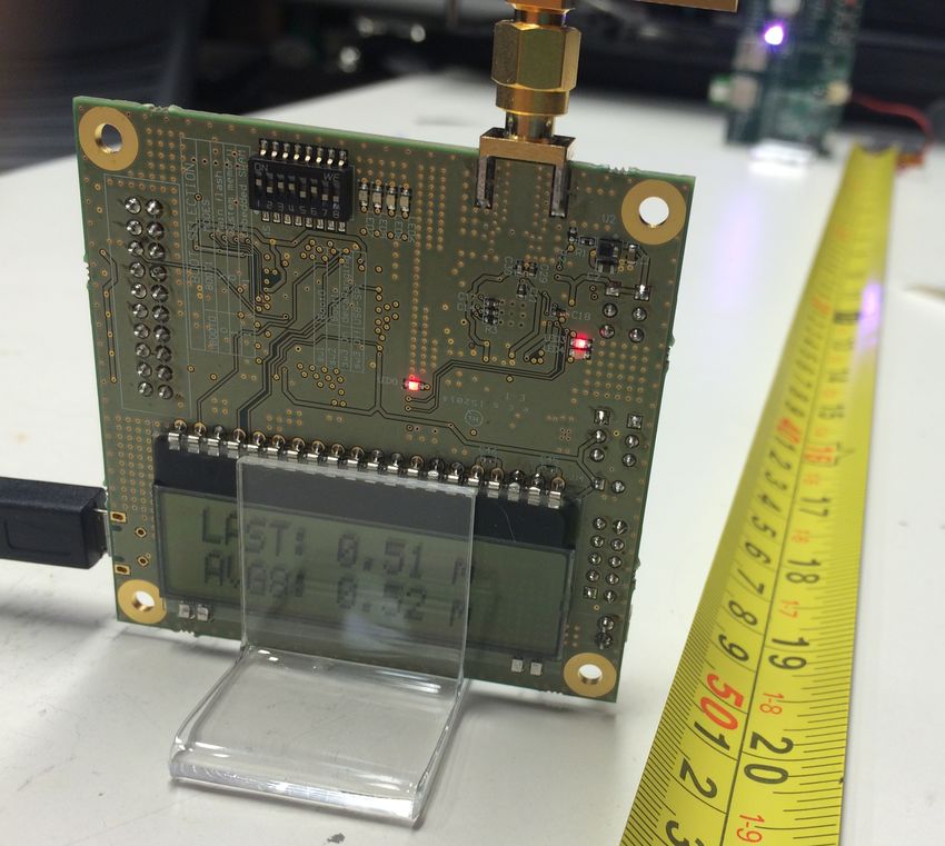
H E A RT H E R E
Infrastructure for Ubiquitous Augmented-Reality Audio

by Spencer Russell

Submitted to the Program in Media Arts and Sciences, School of
Architecture and Planning on August 27, 2015, in partial fulfill-
ment of the requirements for the degree of Master of Science in
Media Arts and Sciences at the Massachusetts Institute of Technol-
ogy

Abstract
   This thesis presents HearThere, a system to present spatial au-
dio that preserves alignment between the virtual audio sources
and the user’s environment. HearThere creates an auditory aug-
mented reality with minimal equipment required for the user.
Sound designers can create large-scale experiences to sonify a city
with no infrastructure required, or by installing tracking anchors
can take advantage of sub-meter location information to create
more refined experiences.
   Audio is typically presented to listeners via speakers or head-
phones. Speakers make it extremely difficult to control what
sound reaches each ear, which is necessary for accurately spatial-
izing sounds. Headphones make it trivial to send separate left
and right channels, but discard the relationship between the head
the the rest of the world, so when the listener turns their head the
whole world rotates with them.
   Head-tracking headphone systems have been proposed and
implemented as a best of both worlds solution, but typically only
operate within a small detection area (e.g. Oculus Rift) or with
coarse-grained accuracy (e.g. GPS) that makes up-close interac-
tions impossible. HearThere is a multi-technology solution to
bridge this gap and provide large-area and outdoor tracking that
is precise enough to imbue nearby objects with virtual sound that
maintains the spatial persistence as the user moves throughout the
space. Using bone-conduction headphones that don’t occlude the
ears along with this head tracking will enable true auditory aug-
mented reality, where real and virtual sounds can be seamlessly
mixed.

Thesis Supervisor: Joseph A. Paradiso, Professor
H E A RT H E R E
Infrastructure for Ubiquitous Augmented-Reality Audio

by Spencer Russell

Thesis Reader

Reader
                                                                   Chris Schmandt
                                                        Principal Research Scientist
                                                                    MIT Media Lab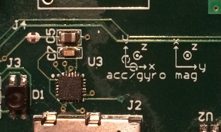
H E A RT H E R E
Infrastructure for Ubiquitous Augmented-Reality Audio

by Spencer Russell

Thesis Reader

Reader
                                                                    Josh McDermott
                                                                  Assistant Professor
                                       MIT Department of Brain and Cognitive Sciences
Acknowledgments There have been many hands at work making this thesis possible, but in particular I’d like to thank the following people, whose contributions have been particularly invaluable. First my advisor, Joe Paradiso, a source of great advice that I’ve learned to ignore at my own peril. His depth of knowledge continues to impress, and I’m grateful he believed in me enough to admit me into Responsive Environments. My readers Chris Schmandt and Josh McDermott, whose feedback and flexibility have been much appreciated. Gershon Dublon, who is so kind and generous. Without his support my user study would not have been physically or emotionally possible, and his work is a continuing inspiration. Brian Mayton is an endless supply of expertise and experience, and there’s no one I’d rather have next to me in the field. Our conversations throughout this project had a tremendous impact, and his capable help in field testing was invaluable. Sang Leigh and Harshit Agrawal who were generous with their knowledge and OptiTrack system. Asaf Azaria who is always ready to help. Julian Delerme and Ken Leidel, whose dedicated work as UROPs was continually impressive. Amna, who keeps things running and is a fantastic help in navigating the Media Lab. Linda and Keira, who helped keep me on track. Jan and Bill, who kept me stocked with encouragement, corn, and bourbon, and graciously opened their home to me during my writing sojourn. My own parents Dennis and Sheryl, who have both pushed and supported me and made me who I am. Finally, my beautiful and talented wife Kate. Her support and understanding during the last few months have made this possible, and I’m looking forward to spending more time with her.
Contents

    Abstract       2

    Introduction            9

    Related Work            11

    Overview       16

    Hardware           18

    Firmware       20

    Orientation Tracking              24

    UWB Ranging                 28

    Bluetooth Low-Energy               31

    iOS Application              34

    Particle Server             36

    GPS Integration              38

    Calibration         40

    Quantitative Evaluation                43

    User Study          51

    Conclusions and Next Steps                  56

    Appendix A: Hardware Schematic and Layout             57

    Appendix B: Field Test Responses                 61

    References         68
List of Figures
1 Overview of the HearThere system components 16
2 Overview of the HearThere hardware 18
3 HearThere head tracker PCB 18
4 Firmware Architecture 20
5 IMU Axis Conventions 26
6 A Symmetric Double-Sided Two-Way Ranging exchange between
the tag and an anchor 29
7 HearThere app orientation screen 34
8 HearThere app range statistics screen 34
9 HearThere app location statistics screen 35
10 HearThere app map screen 35
11 Particle server transactions 36
12 Particle system iterations 37
13 Distance calibration experimental setup 40
14 Anchor configuration for range calibration 40
15 Error data from calibration of all four anchors 41
16 Equipment for anchor calibration 41
17 Turntable configuration for calibration gyro gain 42
18 Evaluation experimental setup 43
19 Localizing A2 using optical tags 43
20 Range comparison 44
21 Overall ranging error (in cm) 44
22 Optical markers placed on the user’s head for tracking 44
23 Particle filter performance 45
24 Particle filter error histogram 46
25 Orientation evaluation 47
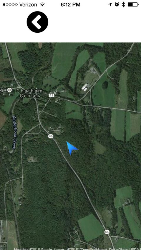
26 Orientation evaluation detail 48hearthere 8 27 Overall error compared to Yaw/Pitch/Roll components. Note the glitches in the yaw and roll errors caused by singularities when pitch approaches ± π2 49 28 Drift evaluation 50 29 Field test area 51 30 Field test localization error 54 31 Localization error grouped by scene 54 32 Localization error grouped by headphone type 54 33 Localization error grouped by whether the source was covered by UWB or not 54 34 Field test tracking data 55
Introduction

  Alice is driving, wearing her auditory display headset, a lightweight device
  that goes around the back of her neck with small transducers on the bones
  just in front of her ears. Based on her GPS location and head orientation,
  the system synthesizes a gentle tone that moves from her current position
  along the road to her next turn, where it emits a soft ping and after
  turning right fades out, then starts again from her current position. As
  she approaches the turn the navigation sound gradually becomes slightly
  louder, as well as more frequent (because it takes less time to get from her
  current position to the turn). While driving Alice is peripherally aware of
  the cars around her because she can hear them, though with her windows
  up and music on she can’t hear them directly. She is hearing the cars
  through her auditory display, spatialized to their actual positions which
  are picked up by her car’s sensors. She briefly wonders why her navigation
  system is taking a different route than normal, but on closer listening
  recognizes the sound of construction ahead in the distance, far beyond her
  real-world perceptual abilities.
  Alice arrives at TidMarsh, a wetland restoration site that is blanketed with
  environmental sensors. Ultra-wideband base stations localize her headset
  with much higher precision than GPS. Alice is now walking through a
  responsive musical composition that responds to the sensor data in real-
  time, surrounding her with a shifting soundscape. A microphone in a
  near-by tree catches the sound of a family of birds, which Alice hears as if
  through an audio telescope. As she walks past the microphones and sensors
  she hears their sound moving around her realistically, seamlessly blending
  to wind and birdsong she hears through her unobstructed ears. Hearing a
  melody she particularly enjoys coming from a nearby sensor she gets close
  to it to hear more clearly.

   While advances in computational power have enabled the use
of real-time head-related transfer functions (HRTFs) and room
modeling to create more realistic sonic environments, the illusion
of presence is immediately shattered when the user moves their
head and hears the whole sonic world move with them.
   We believe that spatial audio that maintains registration with
the real world creates a less intrusive and more compelling audi-
tory display. Further, we consider head-tracking to be an integral
component in any spatialized audio system that attempts to fuse
virtual sounds with the user’s natural auditory environment for
hearthere          10

two related reasons. Firstly, researchers have established that self-
motion is important for resolving front-back confusion errors1 that     1
                                                                          Durand R. Begault, Elizabeth M. Wen-
are otherwise difficult to overcome. Additionally head tracking         zel, and Mark R. Anderson. “Direct
                                                                        comparison of the impact of head track-
is important simply because a user’s head is often not aligned          ing, reverberation, and individualized
with their body, so using body orientation (e.g. from the mobile        head-related transfer functions on the
                                                                        spatial perception of a virtual speech
orientation in a shirt pocket) as in Blum et al.2 causes large per-     source”. 10 (2001).
ceptual errors whenever the user moves their head independently         2
                                                                          Jeffrey R. Blum, Mathieu Bouchard,
from their torso. In addition to the well-established localization      and Jeremy R. Cooperstock. “What’s
                                                                        around me? Spatialized audio aug-
benefits, we believe that head tracking has an important impact         mented reality for blind users with a
on perceived realism, though that area is under-explored in the         smartphone”. 2012.
literature as most research only measures the subjects’ accuracy in
localization tasks, not the accuracy of the illusion.
    Advances in MEMS sensing now allow a full 9DOF IMU (3-
axis each of accelerometer, gyroscope, and magnetometer) in a
low-power IC package, and there are many sensor fusion algo-
rithm implementations available.3 The wider adoption of Ultra           3
                                                                         OlliW. IMU Data Fusing: Complemen-
WideBand (UWB) RealTime Localization Systems (RTLS) has also            tary, Kalman, and Mahony Filter. [Online;
                                                                        accessed 5-November-2014]. Sept. 2013.
driven costs down and availability up of precise localization with
chips available at low cost in small quantities. To take advantage
of these advancements we have created HearThere, a multi-scale
head-tracking audio system that uses UWB localization anchors
when available, but gracefully falls back to GPS when outside
UWB range.
    This work is distinct from the work described in the Related
Work chapter in that it can scale to many users over a large ge-
ographic area. Within the UWB zones the system can represent
audio sources around the user with sub-meter accuracy, and the
designed experience can span many of these zones. This work is
also unusual in that we are committed to preserving the user’s
experience of their natural surroundings, and show that bone
conduction is a viable technology to present spatial audio to users
without occluding their ears.
Related Work
Indoor Localization
Because of the abundance of applications for precise indoor lo-
calization, it is a very active research area with many possible
approaches, and there are a variety of commercial products avail-
able. Mautz4 provides one of the most recent surveys of available 4
Rainer Mautz. “Indoor positioning
techniques. The survey categorizes and compares the technolo- technologies”. Habilitation Thesis. 2012.
gies as well as evaluating their fitness for a variety of use-cases.
Hightower and Borriello5 also describe many of the foundational 5
Jeffrey Hightower and Gaetano Bor-
works in the field and include a well-developed taxonomy. At a riello. “Location systems for ubiquitous
computing”. 8 (2001).
high level most of these technologies can be categorized along two
axes: the signal used (optical, RF, acoustic, etc.) and the properties
of the signal used for localization (time-of-arrival, angle-of-arrival,
signal strength, etc.).
Optical tracking systems are currently popular, particularly
commercial systems such as OptiTrack6 from NaturalPoint and 6
http://www.optitrack.com/
the Vicon7 system. These camera-based optical systems operate by 7
http://www.vicon.com/
transmitting infrared (IR) light that bounces off of retro-reflective
markers on the objects to be tracked. While these systems support
precision on the order of millimeters, one main downside is that
they have no way to distinguish individual markers. Groups of
markers must be registered with the system prior to tracking,
and the system can easily get confused if the marker groups
have symmetries that prevent it from uniquely determining an
orientation.
Other optical systems such as the Prakash8 system and Shad- 8
Ramesh Raskar et al. “Prakash:
owTrack,9 , 10 replace the cameras with infrared projectors and use lighting aware motion capture using
photosensing markers and multiplexed
simple photo receptors as tags. Prakash tags the capture volume illuminators”. 2007.
with grey-coded structured light from multiple simple projectors, 9
Karri T. Palovuori, Jukka J. Vanhala,
and Markku A. Kivikoski. “Shadow-
while ShadowTrack has a rotating cylindrical film around the light
track: A Novel Tracking System Based
source with spread-spectrum inspired coding, and the tags can on Spread-Spectrum Spatio-Temporal
determine their angle by cross-correlating the transmission signal Illumination”. 6 (Dec. 2000).
10
I. Mika et al. “Optical positioning and
with one from a fixed receptor.
tracking system for a head mounted
Recently Valve Corporation has introduced their Lighthouse display based on spread spectrum
technology”. 1998.hearthere 12
system which scans a laser line through the tracked space, similar
to the iGPS system from Nikon Metrology, described by Schmitt
et al.11 Any system based on lasers or projection and intended 11
R. Schmitt et al. “Performance
for user interaction faces a trade-off between performance in evaluation of iGPS for industrial
applications”. Sept. 2010.
bright ambient light (such as sunlight) and eye-safety issues,
though the signal-to-noise ratio can be improved significantly by
modulating the signal. There is little public documentation or
rigorous evaluation of the Lighthouse system, so we look forward
to learning more about it.
SLAM (Simultaneous Location and Mapping) is a camera-
based optical approach that places the camera on the object to be
tracked. This approach is attractive because it does not require any
infrastructure to be installed, but it does require heavy processing
in the tag.
Geometric approaches based on audible or ultrasonic sound
waves have much less strict timing requirements when compared
to RF approaches because sound moves about six orders of magni-
tude slower. Unfortunately the speed of sound varies substantially
with temperature and is affected by wind, as well as subject to dis-
persive effects of the air. Temperature variations in outdoor spaces
are often too large to be compensated for with measurements at
the endpoints.
Several radio-frequency (RF) (including UWB) and electro-
magnetic approaches are also common in this design space. Sys-
tems with transmitters often use a geometric approach including
triangulation (angle-based) or trilateration (distance-based). Other
systems attempt to make use of signals already in the air.
Chung et al.’s geomagnetic tracking system12 builds a database 12
Jaewoo Chung et al. “Indoor location
of magnetic field distortions and then at runtime attempts to sensing using geo-magnetism”. 2011.
locate the tag by finding the most similar database entry. This is
a general approach known as fingerprinting which has also been
widely explored to use ambient WiFi signals, particularly because
geometric approaches using ambient signals have proven difficult
due to field distortions and multi-path effects. Fingerprinting
requires an often-exhaustive measurement process of the space
to be tracked, and reducing or eliminating this step is an active
research area. Accuracy of these methods tends to be on the order
of 1 or more meters.
Ultra-WideBand (UWB) is a popular approach for geometric
tracking because it enables much more precise time-of-flight (ToF)
measurements due to the short pulse length and sharp transi-
tions (see the UWB Ranging chapter for more details). Previous
work13 , 14 has investigated combining GPS and UWB to cover 13
Jose Gonzalez et al. “Combination
both outdoor and indoor localization with promising results. of UWB and GPS for indoor-outdoor
vehicle localization”. 2007.
14
David S. Chiu and Kyle P. O’Keefe.
“Seamless outdoor-to-indoor pedestrian
navigation using GPS and UWB”. 2008.hearthere 13
In particular Chiu et al. show UWB performs favorably even to
high-precision commercial Code DGPS outdoors. Their focus was
more on validating the basic technology in controlled laboratory
environments using off-the-shelf UWB and GPS equipment and
did not attempt to build an integrated system that could be used
by the general public. They also do not evaluate highly-dynamic
motion, instead stopping periodically at waypoints with known
locations.
Location-Based Sound and Augmented Reality Audio
Azuma15 Provides a simple and useful definition of Augmented 15
Ronald T. Azuma et al. “A survey of
Reality, which is that it augmented reality”. 4 (1997).
• Combines real and virtual
• Is interactive in real time
• Is registered in 3-D
The third criteria is useful for separating Augmented Reality
Audio (ARA) from Location-Based Sound (LBS). The key differ-
ence is that in LBS the sound cannot be said to be registered to
a particular location in 3D space. For example, Audio Aura16 is 16
Elizabeth D. Mynatt et al. “Designing
a location-based sound system in an office environment, but not audio aura”. 1998.
augmented reality audio because the sounds are simply triggered
by the user’s location and played through headphones. ISAS17 17
Blum, Bouchard, and Cooperstock,
presents spatialized audio content with a defined location in 3D “What’s around me?”
space, but uses the user’s mobile to determine orientation. While
registration is attempted, it is relatively coarse. They provide some
helpful insights into sound design in an assistive context, and
demonstrate a simple spatializer that models ITD, ILD, and ap-
plies a lowpass filter to simulate ear occlusion effects for sources
behind the user. Their application was able to spatialize up to four
simultaneous sources.
Wu-Hsi Li’s Loco-Radio18 uses a mobile phone mounted to 18
Wu-Hsi Li. “Loco-Radio: designing
the user’s head for orientation tracking, and provides insight into high-density augmented reality audio
browsers”. PhD thesis. 2013.
allowing the user to zoom in and out of the scene, changing the
radius of their perception. Using the location tracker from Chung
et al. they had a location precision of about 1 m, updated at 4 Hz.
LISTEN19 is an ARA system including an authoring system. 19
Andreas Zimmermann, Andreas
The project focuses on context-awareness and providing content Lorenz, and S. Birlinghoven. “LISTEN:
Contextualized presentation for audio-
based on individualized profiles and inferences based on the augmented environments”. 2003.
user’s behavior, such as how they move through the space and
where they direct their gaze.
At SIGGRAPH 2000, AuSIM Inc. presented InTheMix,20 which 20
W. L. Chapin. “InTheMix”. 2000.hearthere 14
presented responsive musical content. The music was spatialized
using HRTFs as well as room modeling, and their system inte-
grated with a number of commercial tracking systems to track the
user’s head. The experience was limited to a 4 m radius circle, and
the user was tethered for audio and tracking purposes.
In the assistive space, SWAN21 is a backpack-sized audio-only 21
Jeff Wilson et al. “Swan: System for
navigation and wayfinding system that uses bone-conduction wearable audio navigation”. 2007.
headphones. It uses commercial GPS receivers for location and
either a digital compass or an off-the-shelf 9-axis IMU, updating
at 30 Hz. Blind users have apparently been successful navigating
with the system, but they do not give any hard metrics that would
be useful for comparison. They also do not specifically address
issues particular to spatial audio delivered over bone conduction.
Spatial Audio Delivery and Perception
ARA systems often use standard in-ear or over-ear headphones,
which interferes with the user’s perception of the world around
them. Härmä et al. present a system22 that includes what they 22
Aki Härmä et al. “Augmented
refer to as hear-through headphones integrate binaural microphone reality audio for mobile and wearable
appliances”. 6 (2004).
capsules into a pair of in-hear headphones. They evaluate their
work with laboratory listening tests. This work is one of a few
to investigate the extent to which users can distinguish between
real and virtual sounds, and in some cases their subjects have a
difficult time distinguishing. The “real” sounds are in this case
mediated through the microphone/headphone device though,
so it is impossible to distinguish whether the confusion is due
to the quality of the virtual sound spatialization or degraded
spatialization of external sounds.
It has been shown that head motion plays an important role in
our ability to localize sound,23 particularly in reducing front/back 23
Hans Wallach. “The role of head
confusion errors. Though some results24 have found less com- movements and vestibular and visual
cues in sound localization.” 4 (1940);
pelling evidence, and no correlation with externalization. Brimijoin Willard R. Thurlow and Philip S. Runge.
and Akeroyd modernized Wallach’s approach25 and showed that “Effect of induced head movements
on localization of direction of sounds”.
as the test signal bandwidth goes from 500 Hz to 8 kHz, spectral 2 (1967); Pauli Minnaar et al. “The
cues become as important head movement cues (in situations importance of head movements for
where they are contradictory). For our purposes it’s important to binaural room synthesis” (2001).
24
Begault, Wenzel, and Anderson,
keep in mind that even experiments that don’t allow head move- “Direct comparison of the impact of
ment assume that the head orientation is known. Without knowing head tracking, reverberation, and
the orientation the system is simply guessing. Because of this head individualized head-related transfer
functions on the spatial perception of a
tracking is a requirement. virtual speech source”.
For navigation tasks spatialized audio has shown to create 25
W Owen Brimijoin and Michael A
lower cognitive load than spoken directions.26 Akeroyd. “The role of head movements
and signal spectrum in an auditory
There have also been several commercial products that have front/back illusion”. 3 (2012).
26
Roberta L. Klatzky et al. “Cognitive
load of navigating without vision when
guided by virtual sound versus spatial
language.” 4 (2006).hearthere 15
added head tracking to headphones for virtual surround sound:
• DSPeaker HeaDSPeaker
• Smyth Research Realiser A8
• Beyerdynamic DT 880 HT
• Sony VPT
Latency has an effect on our ability to localize.27 Azimuth 27
J. Sandvad. “Dynamic Aspects of
error was shown to be significantly greater at 96ms latency than Auditory Virtual Environments”. May
1996.
29ms, and latency had a greater effect than update rate or HRTF
measurement resolution. This provides some guidelines and target
values to shoot for.
Bone conduction headphones have limited bandwidth, which
reduces the audio quality for full-spectrum sources like music.
It also presents challenges when presenting users with spectral
location cues such as HRTFs. Several studies have tried to mea-
sure these issues, though none have been particularly conclusive.
MacDonald et al.28 found that localization performance using 28
Justin A. MacDonald, Paula P. Henry,
the bone conduction headphones was almost identical to a pair and Tomasz R. Letowski. “Spatial audio
through a bone conduction interface:
of over-ear headphones. The sources were filtered to fit within Audición espacial a través de una
the bandwidth of the BC headphones, and their measurements interfase de conducción ósea”. 10 (Jan.
2006).
were very coarse-grained (only in 45° increments) though, so it
only proves suitability for very basic localization. As part of the
SWAN project, Walker et al. evaluated navigation performance
when following spatialized audio beacons using bone conduction
headphones.29 While performance was somewhat degraded from 29
Bruce N. Walker and Jeffrey Lindsay.
previous work with normal headphones, the study at least con- “Navigation performance in a virtual
environment with bonephones” (2005).
firms that unmodified HRTFs presented through bone conduction
headphones can perform basic spatialization.Overview
The HearThere system is comprised of four main components as
diagrammed in Figure 1.
Figure 1: Overview of the HearThere
system components
Head Tracker
IMU UWB
BLE UWB Anchors
HearThere iOS
BLE GPS Morsel HTTP
Server
Orientation Location
ParticleFilters.jl
Audio Rendering
Particle Server
The head tracker hardware is worn on the user’s head and
communicates with a mobile phone or laptop over Bluetooth
Low-Energy (BLE). It is responsible for maintaining an orientation
estimate using its internal inertial measurement unit (IMU) as
well as performing 2-way ranging exchanges with each of the four
Ultra-WideBand anchors, which are EVB1000 evaluation boards
from DecaWave.
The HearThere iOS application is built in the Unity3D gamehearthere 17
engine and maintains a 3D audio scene that is played to the user
through a set of commercial bone-conduction headphones. Audio
output uses the usual headphone output, so switching playback
equipment is easy. As the user moves around in their environment,
the application uses GPS as well as the location and orientation
data from the head tracker hardware and moves a virtual listener
in the game environment to match the user’s movements, creating
a virtual audio overlay. The application can also send the data over
the network using the Open Sound Control Protocol (OSC) which
is useful for data capture and logging or for integrating with other
real-time systems.
When the user is within range of the UWB anchors, the soft-
ware sends the ranges measured by the head tracker hardware to
the Particle Server in the payload of an HTTP request. The Particle
Server is built in the Julia30 programming language, and includes 30
Jeff Bezanson et al. “Julia: A Fresh
an HTTP front-end server using the Morsel HTTP library31 and a Approach to Numerical Computing”
(Nov. 2014).
custom particle filter implementation. The Particle Server sends a 31
https://github.com/juliaweb/
location estimate to the application in the HTTP response, and also morsel.jl
includes the standard deviation vector of the particle mass as an
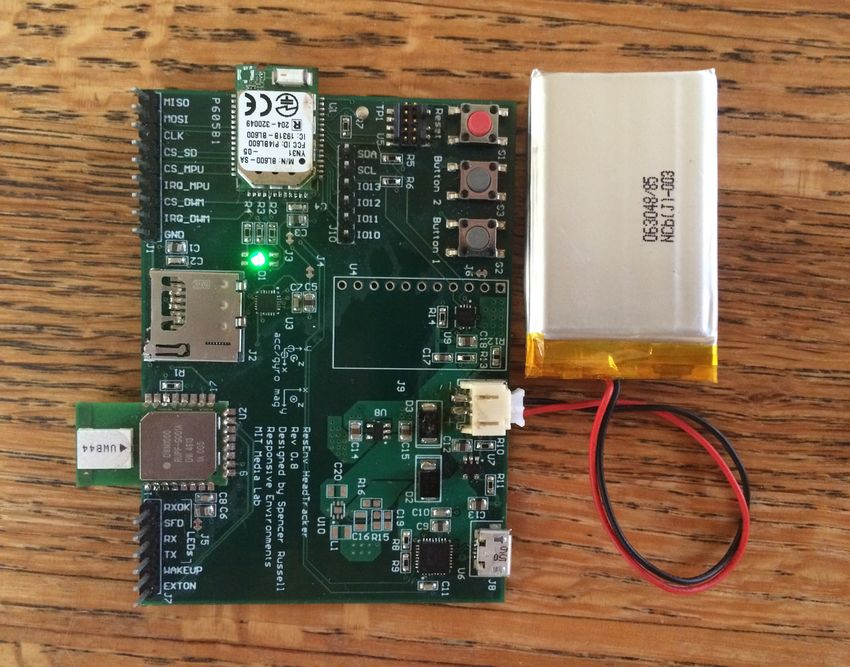
indication of confidence.Hardware
The HearThere HeadTracking hardware (pictured in Figure 3) is
designed in a development board form-factor and optimized for
development and testing. The schematic and layout are included
in Appendix A.
Figure 2: Overview of the HearThere
hardware
Btn0
Btn1 NRF51822
BLE Micro
RGB
LED
MPU9250
I2 C
UART
IMU
SPI
GPIO
STC3100 MCP73832 FTDI DWM1000
Battery Battery USB->Serial UWB Module
Gas Gauge Charger
µSD
LiPo Battery µUSB
The main microcontroller is the nRF51822 from Nordic Semicon-
ductor, which also handles communication with the host over Blue-
tooth Low-Energy. It communicates with the InvenSense MPU- Figure 3: HearThere head tracker
development edition. This version is
9250 IMU over the SPI bus, as well as the DecaWave DWM1000 optimized for ease of development
Ultra-WideBand (UWB) module. It includes a reset button, two rather than board size, and future
versions will be considerably smaller.
general-purpose buttons, and an RGB LED for user feedback. Thehearthere 19 user can switch between indoor (no magnetometer) and outdoor (with magnetometer) modes by holding down Button 1 during boot, and the device indicates its mode by flashing red or green for indoor and outdoor mode, respectively. To enable data logging ap- plications at higher resolution than can fit in the BLE bandwidth, the board has an on-board SD card slot for local data capture. The board is powered by a LiPo battery, which can be charged via the micro-USB port. There is a battery monitoring chip that measures the batter voltage and also integrates current in and out to estimate charge. This data can be reported to the nRF51822 over I2 C. The SPI and I2 C communication busses are broken out to 0.100” headers, as well as all select and IRQ lines. This makes debugging with a logic analyzer much more convenient. Communication to the SD card and battery monitor chip is not yet implemented in the firmware.
Firmware

Architecture

The firmware for the HearThere head tracker is written in C and
runs on the nRF51822 chip from Nordic Semiconductor, which
is built around an ARM Cortex-M0. The code is broken into
modules, each of which consists of a header (.h) file and a source
(.c) file. Figure 4 depicts the major modules, and omits some less
important utility modules for clarity.

                                                                     Figure 4: Firmware Architecture
                                Main

NRF51     NRF51     NRF51     HearThere    HearThere     HearThere
GPIO       SPI      System      BLE        Orientation    Location

          Nordic
                               Madgwick     MPU9250        DW1000
          Stack

  The main responsibilities of each module are:

Main initializes the hardware and the top-level modules, and sup-
 plies each module with a reference to any hardware peripherals
 it needs.

NRF51System handles System-wide functionality such as dis-
  abling interrupts and handling assertion failures.

NRF51GPIO initializes and manages GPIO pins.

NRF51SPI initializes and manages the SPI peripherals, and pro-
 vides an interface for reading and writing from them.

HearThereOrientation reads sensor data from the IMU and
  performs the sensor fusion. It takes a reference to a SPI device
  that it uses to communicate with the IMU, and calls a callback
  when new orientation data is available.
hearthere 21
HearThereLocation reads range data from the anchors. It also
takes a reference to a SPI device that is uses to communicate
with the DW1000 chip from DecaWave. It calls a callback when
new range data is available.
HearThereBLE uses the Nordic BLE API to manage the BLE
connection to the host. It provides an API for sending sensor
data and calls a callback on connection status changes.
MPU9250 initializes and reads from the MPU9250 9-axis IMU
from InventSense.
Madgwick runs the sensor fusion state machine, based on an
algorithm and code from Sebastian Madgwick.32 32
Sebastian OH Madgwick. “An
efficient orientation filter for inertial
DW1000 wraps the provided DecaWave library and provides an and inertial/magnetic sensor arrays”
(2010).
API for UWB ranging.
Peripheral Drivers
You can see in Figure 4, only the Main module depends on the
platform-specific hardware drivers such as NRF51SPI and NRF51GPIO.
Main is responsible for initializing this hardware, and it passes
pointers to the driver’s description structs into any modules that
need access. For instance, the HearThereOrientation module
needs to use the SPI driver to talk to the IMU.
Rather than including the NRF51SPI header, the HearThereOrientation
module includes a generic header SPI.h, and pointers are cast to a
generic SPI struct type. This makes the code much more portable
and decoupled from the hardware implementation, as we can
re-use these modules on a completely different platform simply by
implementing a new set of drivers that satisfy the same interface.
Interfaces to Vendor Code
Along with hardware, vendors often provide source or binary
software that can be included in a project to speed up develop-
ment. In HearThere, we use DecaWave’s low-level API code that
provides functions corresponding to the various SPI commands
that the DW1000 chip supports. Fortunately they provide an easy
way to incorporate their code into your project by supplying func-
tions with predefined names to access the SPI peripheral. The
DecaWaveShim module provides these functions wrapped around
our SPI driver.
Our peripheral drivers rely on the Nordic stack for the NRF51822
chip to provide access to hardware and the HearThereBLE modulehearthere 22 uses their BLE API directly, as well as some useful stack features for scheduling. For the most part we have successfully isolated this platform-specific code from the main functional modules, but in a few cases (e.g. endianness conversion macros) some platform- specific code has crept in. Scheduling HearThere uses a simple cooperative task scheduling design, in which each module has a tick function that is called from the main loop. Each module is responsible for maintaining their own state machine and in general the modules avoid busy-waiting so that other tasks can run. Minimizing latency was a driving design factor, and one of the tightest latency deadlines came from managing the UWB ranging process (see the UWB Ranging chapter for more details), where we need to deterministically handle the incoming UWB message and finish responding within 2 ms. The Nordic BLE stack interrupts the application for 1 ms for each connection (in our case approximately every 20 ms), and the process of responding takes about 600 µs, so we can tolerate a maximum handling latency of 400 µs. Unfortunately running one iteration of the Madgwick sensor fusion algorithm (see page 24) takes 2.8 ms (the nRF51822 does not have a floating-point unit). One option would be to handle the UWB communication in an interrupt context, but this is complicated by the need to use the SPI peripheral to communicate with the DW1000 chip, which could corrupt other in-progress communications. We elected to re-write the Madgwick code into a state-machine so that the computations could be done in smaller pieces of less than 400 µs each. After measuring the various tasks running on the system we estimated that without partitioning the fusion calculations we would need to slow down our ranging rate to under 3 Hz to make our deadlines. With partitioning we estimated we could run at 16.7 Hz, and in practice we were able to get 15 Hz. All tests were run while reading from the IMU and updating the sensor fusion algorithm at 200 Hz, and sending updated orientation over BLE at approximately 35 Hz to 40 Hz. In later experiments the Anchor range update rate was reduced to 7 Hz to 10 Hz to ensure more reliable operation due to more timing headroom.
hearthere          23

SoftDevice

It’s common in embedded RF development to link the application
code against a binary library provided by the vendor that provides
low-level RF functionality, commonly referred to as the vendor’s
stack. This can lock the developer into using the same compiler
as the vendor, as the developer needs to link her application code
against the stack. The Nordic architecture however, builds the
stack code as what they call a SoftDevice . Rather than linking the
stack and application during the build, the SoftDevice is flashed
to a separate region of the chip’s flash memory. All calls from
the application to the SoftDevice’s API are mediated through the
Supervisor Call (SVC) instruction that’s part of the instruction set
used by the ARM Cortex-M0.33                                           33
                                                                          Joseph Yiu. The Definitive Guide to the
    Typically this feature is used for user-space code to trigger      ARM Cortex-M0. Apr. 2011.

operating-system code, and takes an 8-bit value which is passed
to a software interrupt that is handled by the OS. This decoupling
of application and stack development is particularly useful in an
RF development context, as we can use any compiler and toolchain
that supports the ARM. In practice there is some compiler-specific
code in the Nordic-provided header files, but fortunately they
support several common compilers, including GCC, which we
used for our development.
Orientation Tracking
The HearThere head tracker relies on a MEMS inertial measure-
ment unit(IMU) chip from InvenSense called the MPU-9250. It
provides a 3-axis gyroscope (measures angular velocity), 3-axis
accelerometer (measures a combination of gravity and transla-
tional acceleration), and 3-axis magnetometer (measures the local
magnetic field vector).
When the device is motionless (or moving at constant velocity)
the accelerometer measurement should be entirely due to gravity,
which gives a clue as to the orientation (tells us which way is up),
but leaves ambiguity because of possible rotation about that vector.
The magnetic field vector however, is linearly independent and so
the two combined should give a unique orientation solution.
Under acceleration however, we can’t be sure which part of the
measured acceleration is due to gravity. This is where the gyro-
scope comes in, because if we have a previous known orientation
we can integrate our rotational velocity to get a new orientation
relative to the old one. So if we know our initial orientation (for
instance by reading the accelerometer and magnetometer on
bootup), in principle we can rely on the gyroscope to update our
orientation.
In practice this method is hindered by gyroscope noise, which
after integration becomes a random walk that causes our orien-
tation estimate to gradually drift. The search for methods for
correcting this drift by combining the available sensor data (sen-
sor fusion) has been an active research area dating at least to the
inertial guidance system development of the mid-twentieth cen-
tury,34 and common approaches include complementary filters, 34
Donald A. MacKenzie. Inventing
extended Kalman filters, and unscented Kalman filters. In general accuracy: A historical sociology of nuclear
missile guidance. 1993.
the approach is to integrate the gyroscope to capture short-term
variations, while taking into account the magnetometer and ac-
celerometer data over longer time periods to compensate for the
gradual drift. For indoor environments, even the magnetometer is
often not reliable due to sources of electro-magnetic interference
as well as magnetic field distortion caused by nearby metal. Inhearthere 25
these cases, it is often best to simply disable the magnetometer,
though this results in drift around the gravity vector. In the future
we would like to explore alternative approaches to this drift com-
pensation, including comparing the integrated accelerometer data
with position data from the localization system. This should help
enable drift-free operation even when without the benefit of the
magnetometer.
Sensor Fusion
HearThere uses the Madgwick algorithm35 based on prior suc- 35
Sebastian OH Madgwick, Andrew JL
cess36 and the availability of efficient C-language source code that Harrison, and Ravi Vaidyanathan. “Esti-
mation of IMU and MARG orientation
could be run on our microcontroller. using a gradient descent algorithm”.
The output of the Madgwick algorithm provides a quaternion 2011.
36
Brian Mayton. “WristQue: A Per-
relating an estimated global coordinate frame to the coordinate sonal Sensor Wristband for Smart
frame of the IMU. What we are actually interested in though, Infrastructure and Control”. MA thesis.
is the quaternion relating the actual earth frame to the user’s 2012.
head. To make this transformation we introduce the four relevant
coordinate frames: Earth, Estimated Earth, Sensor, and Head, and
the quaternions that relate each frame to the next. Earth
Est q relates the
actual earth frame to where the Madgwick algorithm thinks it is.
This transformation represents an error that could be due to a lack
of magnetic reference (as when we are operating in indoor mode),
or error due to magnetic declination. EstSensor q is the quaternion
reported by the Madgwick algorithm. SensorHead q relates the sensor to
the user’s head, based on how it is mounted or worn. Here we
use the notation A
B q = ( q0 q1 q2 q3 ) = q0 + q1 i + q2 j + q3 k to
be the quaternion going from frame A to B. The i, j, and k terms
correspond to the x, y, and z axes, respectively. See Kuipers37 for a 37
Jack B. Kuipers. Quaternions and
more complete treatment of quaternions. rotation sequences. 1999.
Because we want the overall transformation from Earth to Head,
we set
Earth
Head q = Earth Est Sensor
Est q × Sensor q × Head q (1)
Our iOS application has a ReZero button that the user presses
while looking directly north with a level head to determine Earth
Est q.
This operation typically happens at the beginning of an interaction,
but can be repeated if the orientation estimate drifts. The position
of looking due north aligns the users head coordinate frame with
Earth’s, sohearthere 26
Earth
Head q = (1 0 0 0) (2)
Earth Est Sensor
Est q × Sensor q × Head q = (1 0 0 0) (3)
Est Sensor ∗
Sensor q × Head q = Earth
Est q (4)
Sensor ∗
(Est
Sensor q × Head q ) = Earth
Est q (5)
Where × is quaternion multiplication and q∗ indicates the
conjugate of q, or (q0 −q1 −q2 −q3 ). Also note that because
the set of unit quaternions double-covers the set of 3D rotations,
(q0 q1 q2 q3 ) represents the same rotation as (−q0 −q1 −q2 −q3 ).
We assume that Sensor
Head q is known because we know how the
sensor is mounted, so the above expression allows us to calculate
Earth q, which we can plug into eq. 1 every sensor frame to get the
Est
overall head orientation relative to the Earth frame. This happens
in the iOS application.
Axes and Handedness
When working in 3D systems it is common to deal with data,
algorithms, or documentation that assumes different axis con-
ventions than your system. An axis convention can be described
by the physical interpretation of each of the three axes (x, y, and
z), as well as the direction of positive rotation (right-handed or
left-handed). For instance, in the accelerometer of the MPU-9250
(pictured in Figure 5) the x axis points to the right, the y axis
points up, the z axis points out the front of the PCB. This coordi-
nate system can be said to be right-handed because if you place the
thumb, and index fingers of your right hand along the x and y
axes respectively, your middle finger will point along the z axis.
Notice this also works for any rotation of the axes, i.e. yzx and
zxy.
The gyroscope follows a slightly different right-hand rule,
where if you place your thumb along the axis of rotation, your Figure 5: Portion of the HearThere
head tracker PCB showing the axis
fingers curl in the direction of positive rotation. Notice in Figure
conventions used by the MPU-9250
5 that the magnetometer uses a left-handed coordinate system, IMU (U3)
requiring a change of axis in the firmware. Though there are two
handedness rules (one for rotation and one for axis relations),
they are related in that the handedness of the axes should always
match the handedness of rotation, in order for cross-products and
quaternion math to work as expected.
The published implementation of the Madgwick algorithm uses
a North-East-Down or NED axis convention, so x points North, y
points East, and z points Down. This is a right-handed coordinatehearthere 27
system, so we chose to standardize the IMU axes in a right-handed
system as well by swapping the x and y axes of the magnetometer.
The Unity3D game engine that we used to implement our iOS
application uses a left-handed coordinate system where x points
East, y points Up, and z points North.
Table 1: Coordinate system summary
x y z Hand
Madgwick North East Down Right
Unity East Up North Left
So to take a vector vm = [ xm , ym , zm ] in the Madgwick space and
convert to Unity space gives vu = [ym , −zm , xm ] and a quaternion
qm = (qm0 qm1 qm2 qm3 ) in Madgwick space becomes qu =
(qm0 −qm2 qm3 −qm1 ) in Unity space. Our firmware transmits
the quaternion in Madgwick axes and it is converted to Unity axes
in the iOS application.UWB Ranging
Ultra-WideBand or UWB, describes the use of RF signals with an
absolute bandwidth of greater than 500 MHz or relative bandwidth
greater then 20 %.38 After a period of initial development in the 38
S. Gezici et al. “Localization via ultra-
1960s and 1970s39 there was a resurgence of interest in the 90s wideband radios: a look at positioning
aspects for future sensor networks”. 4
corresponding to the development of much less expensive and (July 2005).
lower-power receivers than were previously available40 .41 One 39
Gerald F Ross. “Transmission and
of the key insights was the use of a range-gate sampler that con- reception system for generating and
receiving base-band pulse duration
tinually sweeps through a cycling delay. This technique is also pulse signals without distortion for
used in oscilloscopes to be able to super-sample periodic signals. short base-band communication
system”. US3728632 A. Apr. 1973.
While most of this initial research focused on RADAR applications,
T. McEwan and S. Azevedo. “Microp-
40
in the 1990s more research shifted into UWB as a short-range, ower impulse radar” (1996).
high-bandwidth communication channel intended to stem the 41
Thomas E. McEwan. “Ultra-wideband
proliferation of wires connecting consumer devices like monitors receiver”. US5345471 A. Sept. 1994.
and other computing peripherals.42 42
M.Z. Win et al. “History and Applica-
Allowing the frequency spectrum of a signal to be wide means tions of UWB [Scanning the Issue]”. 2
(Feb. 2009).
that in the time domain the signal can operate with very short
pulses with sharp transitions. This property is what makes UWB
particularly suitable for measuring the time-of-flight of RF pulses,
even in the presence of reflections (off of walls, floors, and objects
in the area). Consider a signal that is longer than the delay time
of its reflections. Though the receiver gets the direct signal first,
the reflections overlap the direct signal and make decoding the
transmission more difficult, particularly in the presence of noise.
By increasing the bandwidth of our transmitted signal we can
shorten the duration to be shorter than the reflection delay, so
the complete signal can be decoded and any delayed identical
packets can be ignored. Note that reflected signals can still be a
source of error in cases where the direct signal is blocked by an
obstacle, known as non-line-of-site (NLOS) conditions. In these
cases the receiver can mistake a reflected signal for the direct,
which over-estimates the range.
We use what is known as Two-Way Ranging (TWR) to determine
the distance between our device (the Tag) and several fixed Anchors
that are at known locations. Without noise we could then solve forhearthere 29
the location of the tag analytically using trilateration. Given that
noisy signals are inevitable however, there is often no analytical
solution to the trilateration problem, so we have implemented the
particle filter described in the Particle Server chapter.
Two-Way Ranging
In a two-way ranging configuration, two devices exchange mes-
sages back and forth to determine the round-trip time-of-flight be-
tween them, from which they determine the distance. Specifically
we use a variant known as Symmetric Double-Sided Two-Way
Ranging (SDS-TWR) which can compensate for clock drift between
the two devices.43 43
Sources of Error in DW1000 Based
A ranging exchange is shown in Figure 6, where τr is a round- Two-Way Ranging (TWR) Schemes.
Application Note APS011. 2014.
trip time and τp is the device processing time. First it’s important
to note that the DecaWave API gives the ability to schedule an Tag Anchor
outgoing message for some time in the future with the same
accuracy that is used for message timestamping, so the device’s
processing time includes both the time spent actually processing τr1 τp1
the message and a delay. This allows the processing time to kept
consistent even if the firmware takes a varying amount of time
to handle the message. At first, it seems that the time of flight τ f
τp2 τr2
could be determined by the tag using eq. 6.
1
τf = (τ − τp1 ) (6)
2 r1
Figure 6: A Symmetric Double-Sided
Unfortunately this neglects the real-world fact that the clocks Two-Way Ranging exchange between
on the two devices are in general not running at exactly the same the tag and an anchor
speed. To resolve this we introduce ea and et as the clock speed
[ a]
error on the anchor and tag. We’ll define τn = (1 + ea )τn as the
time period τn as measured by the anchor, and similarly for the
tag.
So while eq. 6 gives the correct answer in theory, we can only
measure time relative to the local clock, so what we get is
1 [t] [ a]
τ̂ f = τr1 − τp1
2
1
= (1 + et )τr1 − (1 + ea )τp1
2
so the error τ̂ f − τ f is given by
1
(1 + et )τr1 − (1 + ea )τp1 − τr1 + τp1
2
1
et τr1 − ea τp1
2hearthere 30
Because the time of flight is typically at least several orders of
magnitude smaller than the processing time, we can simplify by
assuming τr1 ≈ τp1 , (that is, the overall ranging time is dominated
by the receiver’s processing time) so the error is given by
1
(et − ea )τp1
2
So the error is proportional to the processing time and the dif-
ference in error. For real world clock drifts and processing times
this error can be significant, so we use the full exchange shown in
Figure 6. Now the time of flight should be 14 (τr1 − τp1 + τr2 − τp2 ).
Following a similar logic, the error is
1 [t] [ a] [ a] [t]
τr1 − τp1 + τr2 − τp2 − τr1 + τp1 − τr2 + τp2
4
1
(1 + et )(τr1 − τp2 ) + (1 + ea )(τr2 − τp1 ) − τr1 + τp1 − τr2 + τp2
4
1
et τr1 − et τp2 + ea τr2 − ea τp1
4
Making the same simplification as before we get
1
et τp1 − et τp2 + ea τp2 − ea τp1
4
1
(et − ea ) τp1 − τp2
4
So the error is still proportional to the difference in clock errors, but
now is proportional to the difference in processing time on both
sides, instead of the absolute processing time.
While this approach works with for a single tag and small num-
ber of anchors, each ranging measurement takes four messages
(three for the ranging and one for the anchor to report back the
calculated range), and ranging to each anchor must be done se-
quentially, which adds error if the tag is in motion. Future work
will implement a Time-Difference-of-Arrival (TDOA) approach
which will only require a single outgoing message from the tag
that will be received by all anchors within communication range.
This approach shifts complexity to the infrastructure, which must
maintain time synchronization between all the anchors. Tradi-
tionally UWB systems have used wired synchronization cables,
but recent work44 in wireless clock synchronization has shown 44
Carter McElroy, Dries Neirynck, and
that at least in controlled lab settings it is possible to get sufficient Michael McLaughlin. “Comparison
of wireless clock synchronization
clock synchronization to accurately locate tags without wiring the algorithms for indoor location systems”.
anchors together. 2014.Bluetooth Low-Energy
The HearThere head tracking PCB communicates with the user’s
mobile phone or computer over Bluetooth Low-Energy (BLE), also
known as Bluetooth Smart. For more details on the BLE protocol,
“Getting Started with Bluetooth Low Energy”45 is an excellent and 45
Kevin Townsend et al. Getting Started
concise starting point. with Bluetooth Low Energy: Tools and
Techniques for Low-Power Networking. 1
edition. Apr. 2014.
Connection Interval
A BLE Connection is a contract between two devices, wherein
the devices agree to establish radio contact at a specified interval
(the Connection Interval) and on a predefined sequence of channels
(frequency hopping). The connection interval is an important
part of a device’s design because it determines the latency, jitter,
and bandwidth of communications. Because messages are only
exchanged during connection events, messages generated during
the interval will be delayed until the next event. Bandwidth is
affected because devices have a limited buffer to store pending
messages, which limits the number of messages that can be sent
during a given connection event. In practice this limit is often as
low as two to four messages.
Different devices have widely-varying requirements for their
connection interval, depending mostly on trading battery con-
sumption for latency and bandwidth. To manage these diverse
requirements, when a new connection is being established there
is a process of negotiation. The BLE Peripheral is able to request
a particular range of connection parameters (including the con-
nection interval), but it is up to the Central to decide what the
final parameters will actually be. The peripheral may make these
requests when the connection is first established or at any time in
the future. The BLE specification allows connection intervals to be
between 7.5 ms and 4 s, but a Central does not have to support the
whole range.
Apple’s document “Bluetooth Accessory Design Guidelines for
Apple Products” says:hearthere 32
The connection parameter request may be rejected if it does not
comply with all of these rules:
• Interval Max ∗ (Slave Latency + 1) ≤ 2s
• Interval Min ≥ 20ms
• Interval Min + 20ms ≤ Interval Max Slave Latency ≤ 4s
• connSupervisionTimeout ≤ 6s
• Interval Max ∗ (Slave Latency + 1) ∗ 3 < connSupervisionTimeout
Through trial-and-error we have determined that as of January
14, 2015, the lowest connection interval possible on an iPhone 5S
is 15 ms to 17 ms, achieved through requesting an interval between
10 ms to 20 ms. Additionally this request must be made after the
initial connection negotiation, even if the same parameters were
used for the original connection.
Services
BLE functionality is advertised and provided to a client by a server
through Services. To that end, the HearThere head tracker provides
two services: The Attitude and Heading Reference System Service
(AHRS) which provides quaternion orientation estimates and the
Ranging Service which provides ranges to anchors.
The Ranging Service provides a single characteristic that it uses
to notify the client of newly-available range data. The characteris-
tic data format is defined by the struct:
typedef struct __attribute__ ((__packed__)) {
uint8_t seqNum;
float rangeMeters[4];
} ble_ranging_range_value_t;
Where the seqNum field is incremented with each new value
and rangeMeters is an array of ranges to the 4 anchors in meters.
Each value is transmitted in little-endian order. When there is
a communication failure to a given anchor during the ranging
process, the device reports −1.
The AHRS Service contains an Orientation characteristic and
a Calibration characteristic. The Calibration Characteristic is a
single byte that can be written by the client to put the device in
calibration mode, where it will transmit raw IMU data rather than
the orientation determined by the sensor fusion algorithm. The
Orientation characteristic has the format:hearthere 33
typedef enum {
// used to send the fused data
AHRS_DATA_QUATERNION,
// used to send the raw 16-bit integer sensor data
AHRS_DATA_RAW_DATA
} ble_ahrs_data_type_t;
typedef struct __attribute__ ((__packed__)) {
uint8_t sequence;
ble_ahrs_data_type_t type;
union {
struct __attribute__ ((__packed__)) {
float w;
float x;
float y;
float z;
} quat;
struct __attribute__ ((__packed__)) {
int16_t accel_x;
int16_t accel_y;
int16_t accel_z;
int16_t gyro_x;
int16_t gyro_y;
int16_t gyro_z;
int16_t mag_x;
int16_t mag_y;
int16_t mag_z;
} raw;
};
} ble_ahrs_orientation_value_t;
In calibration mode the device simply sends the data as mea-
sured, and in normal mode it sends the 4-component quaternion
orientation given by the sensor fusion algorithm (see the Orienta-
tion Tracking chapter).You can also read