INSTALL INSTRUCTIONS A90 Toyota Supra Turbo Kit - AMS ...
←
→
Page content transcription
If your browser does not render page correctly, please read the page content below
A90 Toyota Supra Turbo Kit
INSTALL INSTRUCTIONS
2
                                                                  2

Introduction
   The goal of AMS Performance is to provide the highest quality, best performing products
   available. By utilizing research and development, and rigorous testing programs AMS
   Performance will never compromise the quality or performance of our products. In
   addition, AMS Performance will only provide the finest customer service offering only
   parts and advice that are in the best interests of the customer. AMS Performance was
   built on a foundation of integrity. This is who we are; this is what you can count on.

   A vehicle modified by the use of performance parts may not meet the legal requirements
   for use on public roads. Federal and state laws prohibit the removal, modification, or
   rendering inoperative of any part or element of design affecting emissions or safety on
   motor vehicles used for transporting persons or property on public streets or highways.
   Use or installation of performance parts may adversely affect the drivability and reliability
   of your vehicle, and may also affect or eliminate your insurance coverage, factory
   warranty, and/or new OEM part warranty. Performance parts are sold as-is without any
   warranty of any type. There is no warranty stated or implied due to the stresses placed
   on your vehicle by performance parts and our inability to monitor their use, tuning, or
   modification.

   These instructions are provided as a guide only as there are many variables that cannot
   be accounted for concerning your particular vehicle, including but not limited to model
   year differences, model differences, the presence of non-OEM parts, and modifications
   that may already be or were previously installed. A basic knowledge of automotive parts
   and systems is helpful but a better understanding of the parts and systems on your
   particular vehicle may be required.

   If you have any questions or issues at any time during the installation of your AMS
   Performance product(s) please call us for technical assistance. The AMS Performance
   tech line can be reached during business hours at 847-709-0530 for AMS Performance
   products only.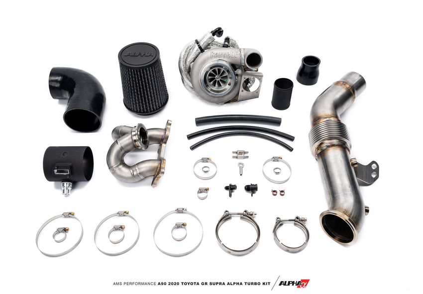
3

Table of Contents

  02   Introduction

  04   Disassembly

  10   Installation

  12   Adjustments and Tuning
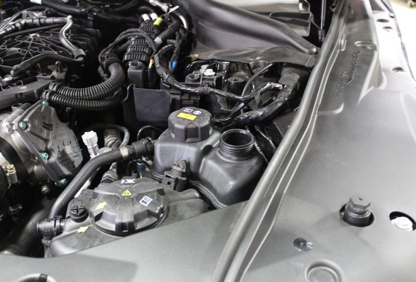
4

1. Start by draining fluids. If you do not plan on changing your oil you do not have to drain it but the
cooling system will need to be drained. Remove the plastic and aluminum undertrays. There are ten
16mm bolts and multiple 8mm screws holding these in place.

2. Remove the smaller cap from on the auxiliary coolant reservoir and remove the lower fitting on the
passenger side auxiliary radiator. Collect the coolant in a clean pan or bucket if you intend to reuse it.
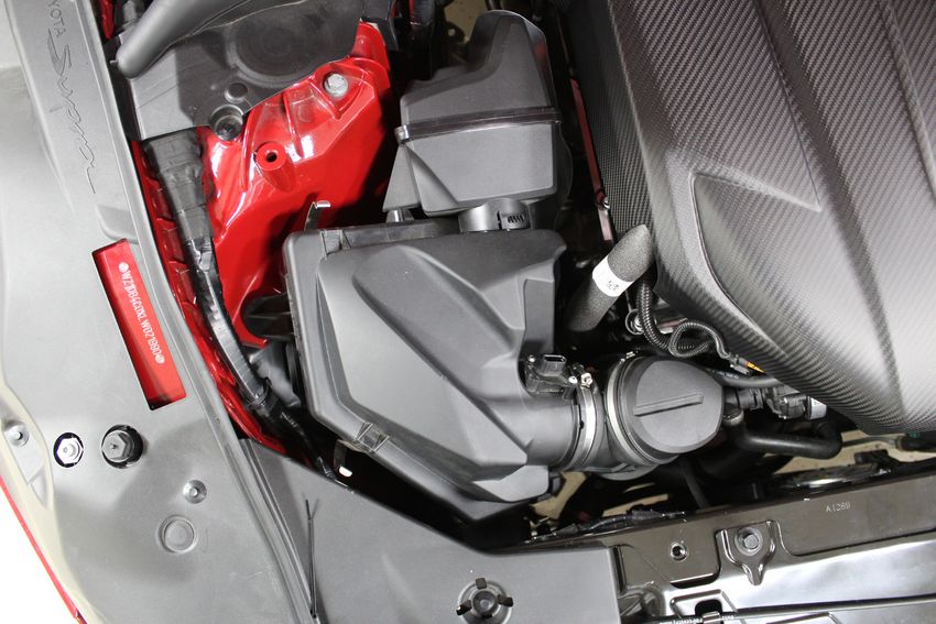
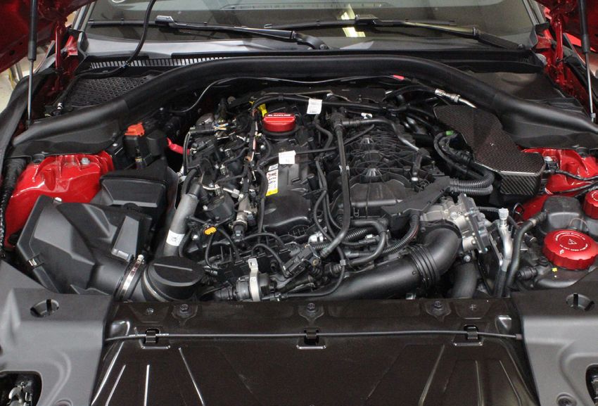
5

3. Once the side radiator is drained you can move into the engine bay. Start by removing the engine
cover and intake air box.

4. Push the white locking tab up and remove the electrical connector on the airbox. Then, using a flat
blade screwdriver or 6mm socket, loosen the clamp holding the intake tube to the airbox. If your car is
equipped with a strut tower brace, now would be the time to remove it.
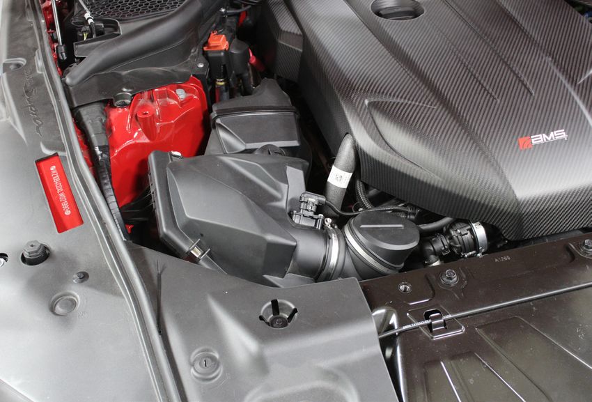
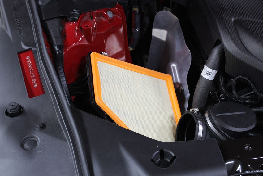
6

5. Release the four metal clips to remove the upper air box.

6. There are three grommets holding the air box in. One on the side and two underneath. Grab ahold
of the lower airbox assembly and pull it straight up out of the grommets one at a time.
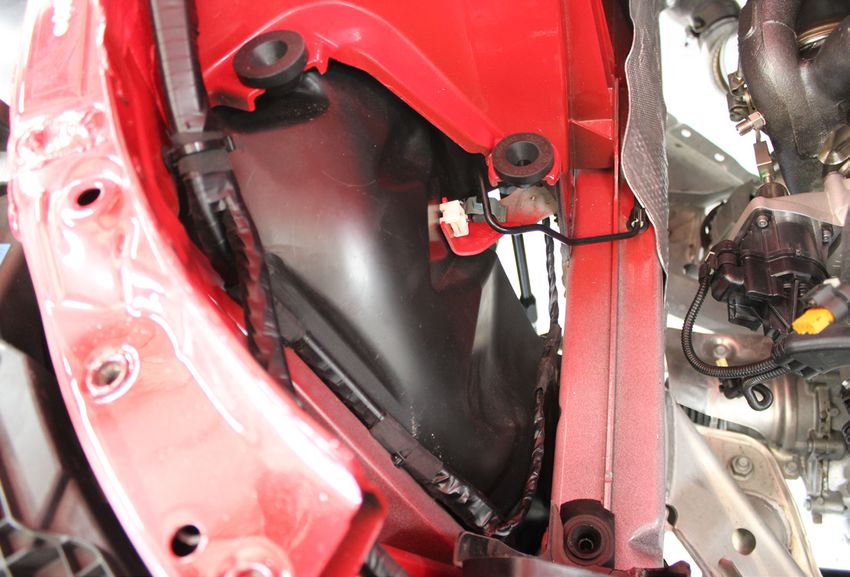
7

7. If the grommets came out with the airbox, remove them from the air box and reinstall them back in
the car.

Note: The rectangle grommet has a cutout for the pinch weld under the airbox. Position it as shown.
8

8. Remove the intake tube. First release the “C” shaped retainer clip holding the tube to the compres-
sor inlet as shown. One end is visible on the top, the other end is underneath the tube.
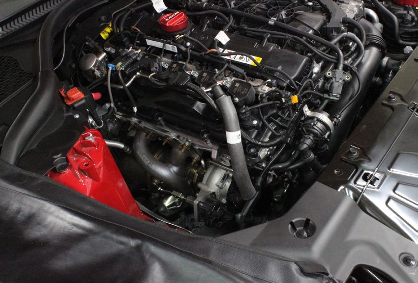
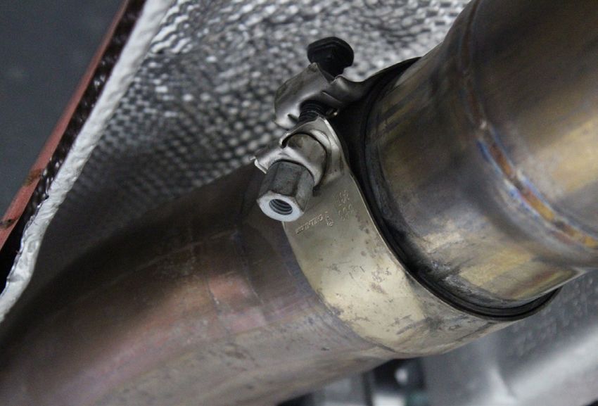
9

9. Now wiggle the intake tube off the turbo about an inch or so to reveal the crankcase hose connec-
tion. Squeeze the connector and pull the line off. Then remove the inlet tube.

10. With the intake side of the turbo removed, you can now remove the factory downpipe. Loosen the
12mm nut on the back side of the exhaust mount. This will allow you to push the rest of the exhaust
back enough to make room for the downpipe to come out. Next, loosen the 10mm nut on the clamp
that holds the two pipes together.
10

11. Remove the two 10mm copper nuts on the upper downpipe mounting bracket. Loosen the V-band
clamp that connects the downpipe to the turbo. Twist the downpipe clockwise to free it from the two
mounting studs and pull the downpipe out of the exhaust pipe. This may take some effort and is best
to do with an extra set of hands. If your vehicle has high mileage or you live in an area prone to rust,
some penetrating fluid beween the two pipes may make this job easier.

12. With the downpipe out of the way you can start removing the oil and coolant lines from the engine
block. All of these lines are held in place with T27 Torx head bolts. Start with the rear coolant return
line. There will likely still be coolant trapped behind this fitting so it is a good idea to have a drain in
place and some shop rags handy. Remove the bolt on the fitting itself as well as the rubber support
clamp bolt. Once both bolts are removed, grab and wiggle the fitting out.
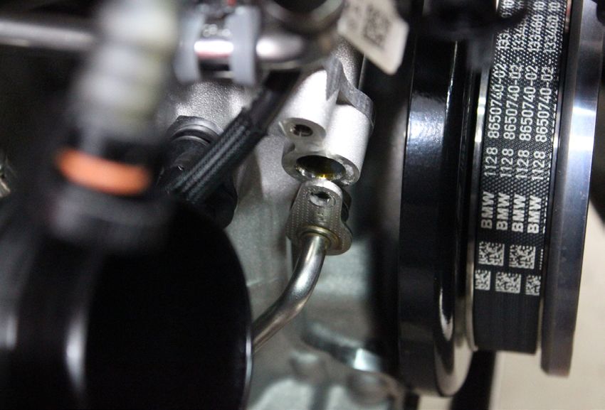
11

13. The oil feed fitting is located at the front of the block close to the harmonic balancer. Remove the
bolt and the fitting. Have a rag handy to catch any oil drips.

14. The oil drain fitting is located directly under the turbo. Remove the bolt and wiggle the fitting free.
12

15. The last fitting to remove is the coolant feed line. This connects to the auxillary water pump that is
bolted to the front of the motor. Release the clip on the outlet fitting and slide the hose off the pump.
13

16. With all the lines disconnected you can now remove the turbo. There is one T30 Torx bolt on the
bottom and six 10mm copper nuts on the exhaust flange. Remove the lower bolt first then the cop-
per nuts. Once they are all removed the turbo will simply lift out of the engine bay. Set it on a clean
work space, some of the lines and o-rings as well as the electronic wastegate actuator will need to be
transferred to the new turbo.

17. You will need to modify the coolant feed line. You need to cut the rubber section of hose and at-
tach it to the heat wrapped braided stainless line in order to reuse the factory water pump fitting. Use
the pictures below as a guide of where to cut the factory line. Use one of the #18.5 Oetiker clamps to
secure the hose onto the barbed fitting of the new coolant feed line.
14

18. The o-rings from the factory enigine block oil fittings need to be transferred over to the AN adapter
fittings prior to installation. Use a pick or small flat blade screwdriver and gently remove the o-rings.
use a dab of silicone lubricant on the o-rings and install them on the new fittings provided in the kit.

19. The last line you will need to modify is the coolant return line. You will reuse the factory engine
block fitting with the new hose. To do this you need to remove the fitting from the factory hose which
will require you to cut the clamp off of the hose. We recommend using a small cut off wheel on a ro-
tary tool. Once the fitting is free, slide the other #18.5 Oetiker clamp over the line and push the fitting
into the hose. It is recommended to wait until the turbo is loosely installed and the fitting can be bolted
into the block before tightening this clamp in order to get the orientation correct.
15

20. With all the lines prepared for the new turbo, you can install the adapter fittings in the engine
block. The engine oil feed and return fittings are installed in the same locations using the same facto-
ry Torx head bolts. Make sure the o-rings are in place and lubricated with a small amount of silicone
lubricant before being installed. The larger -8 fitting is for the oil return and the -4 fitting is for the feed
line.

21. Next you will need to transfer the electronic wastegate actuator from your stock turbo to the new
one. Before you remove any of the factory components it is a good idea to take some measurements
to help accurately set up the actuator on the new turbo. Push the linkage in towards the actuator until
the wastegate door is fully closed and seated firmly. Using a caliper, record the distance that the end
of the shaft of the actuator sticks out of the body. See pictures below for how we recorded our mea-
surements. This information will be critical once the new turbo is installed to ensure proper wastegate
operation.
16

22. Once you have the measurements recorded, you can remove the E-clip and pop the factory con-
nection pin out of the linkage arm.This part will be reused. Remove the four T25 torx bolts holding the
actuator in place. The metal cup that covers the end of the actuator will not be reused.
17

23. Transfer the wastegate actuator to the new compressor cover, it will sit oriented 180 degrees from
the factory location so the harness will reach the connector.

24. With the actuator installed on the new compressor cover, you can install the connection block and
linkages. To do this correctly, ensure that the shaft of the actuator is still set at the resting distance
you measured earlier and loosely install the linkage as shown. Then, push the wastegate door arm
closed firmly and ensure the wastegate door is seated. Then, tighten all the jam nuts on the linkage at
this position. See tech note below for proper orientation of the connection block. This should get you
very close if not perfectly adjusted for proper wastegate actuation, but if small adjustments need to be
made the linkage will be accessible once installed.
18

TECH NOTE:
When assembling the wastegate actuator linkage assembly, ensure that the components are posi-
tioned correctly as follows. Improper alignment may cause wastegate control issues. The pivot con-
nection must allow the rod end to pivot on the same axis as the wastegate lever. To achieve this, the
rotating pivot on the wastegate lever and the pin on the pivot connection must be in alignment.

25. With the wastegate linkage all set up, you can clamp the turbo to the manifold and get it installed
on the engine. Orient the v-band clamp as shown for easy access once the turbo is installed.
19

26. Place the turbo into the engine bay and get the lines loosely routed in the direction they will go
and make sure they don’t get hung up on anything. Slide the manifold over the exhaust studs and
tighten it with the copper exhaust nuts.
20

27. Install the rear coolant return line into the block and tighten the bolt. If you have left the Oetiker
clamp loose now would be the time to clamp it tight.

28. The oil return line will route through the motor mount to the -8 AN fitting in the block. Use a dab of
silicone lubricant on the threads to prevent them from galling.
21

29. The oil feed line will be routed to the fitting in the block and the coolant feed line can be clamped
to the cut hose from the auxillary water pump.

30. With all the lines routed you can start installing the new downpipe. This will be a reverse of the
removal process. Transfer over the factory oxygen sensors in the same locations they were on the
stock downpipe. You may need to loosen the v-band clamp that connects the turbo to the exhaust
manifold in order to properly align the downpipe.
22

31. Now you can move on to the charge pipe. Install the straight silicone adapter on the outlet of the
compressor cover, followed by the short powdercoated jumper and the 90 degree silicone adapter.
Leave all the clamps loose until the charge pipe is fully installed. Do not use any type of lubricant
when installing the charge pipe, this can cause coupler failures under boost.

32. Install the adapter onto the throttle body and transfer the sensors to the new charge pipe.
23

33. To make installing the new charge pipe easier, you can remove the bracket that mounts the small
electric water pump to the front of the engine. Remove the 10mm nut on the bottom of the bracket
and disconnect the hoses to remove the pump. This will provide you more space to slide the charge
pipe in without damaging anything.
24

34. Push the charge pipe into the lower silicone coupler and ensure both top and bottom silicone
couplers slide over the bead rolls on the pipe. You may need to clock the charge pipe one way or
the other to get it to sit square in the couplers and ensure that the sensors can be plugged in without
stretching the harnesses. Once you are happy with the fitment, tighten all the clamps to 8 lb/in and
re-install the water pump if you removed it.
25

35. With the charge pipe installed the last thing to do will be to install the intake and air filter as well
as the vacuum lines. To make routing vacuum lines easier, we included reinforced silicone lines to
replace the factory molded plastic lines. This will involve cutting the factory lines off of their fittings to
be re-used. Loosely install the 4 inch diameter 90 degree silicone intake coupler and powder coated
intake tube. Swap your factory MAF sensor into the intake tube. Make sure the arrow points towards
the turbo.

36. The smallest diameter hose will be used to replace the crankcase vent tube that routes from
the engine block to the factory intake. Using the same engine block fitting, this hose will route to the
barbed fitting on the powder coated intake pipe. Use the red spring clamp on the engine block side
and the green clamp on the intake side.
26

37. The 10mm hose will replace the lines that connect to the intake manifold.
27

TECH NOTE: We removed the plastic guard covering the wiring for the wastegate actuator to create
some slack, this is not necessary if you do not wish to do so. The other connector will not be used
and can be zip tied out of the way.
28

38. The short section of 19mm hose replaces the large PCV line that runs from the top of the valve
cover to the large fitting on the intake tube. This hose will be secured with the included #34.6 Oetiker
clamps
29

39. Last but not least, install your Alpha air filter.
30

BLEEDING
Once the car is back together, you will need to vacuum bleed the system to ensure it is properly
refilled. The intercooler system on these vehicles is difficult to bleed to avoid an “air lock” condition
due to the intercooler being the highest point. Since the intercooler pump is not self-priming, it cannot
move air. If one part of the system has an air pocket close to the pump, no coolant will flow. It is also
important to know that damage may occur to the intercooler pump if it is run dry. Avoid this at all cost!
Standard filling procedures will not work for this application. The method we prefer involves using a
widely available system called an Air Lift or Vacuum Venturi System. These systems use compressed
air to draw the cooling system under a vacuum and remove all the air from the system. The vacuum
then draws in coolant into the entire system. Almost no bleeding is required after.
https://www.matcotools.com/catalog/product/MCR103A/COOLING-SYSTEM-FILLER/
https://www.matcotools.com/catalog/product/MPT0445/COOLING-SYSTEM-ADAPTER-BMW/
• Follow your tools manufacturer instructions for bleeding.
• After completion, test drive the vehicle and check the fluid level in the reservoir.
• Once the system is properly bled, Enjoy!
You can also read