Installation, Operating & Maintenance Instructions Symmetrical flow control & isolation valve
←
→
Page content transcription
If your browser does not render page correctly, please read the page content below
Installation, Operating &
Maintenance Instructions

Symmetrical flow control & isolation valve

Series 670
DN 250 mm (I. D. 10")
This manual is valid for the following product ordering number

67048-JH52-ADU1 (left)
67048-JH52-ADV1 (right)

Sample picture: 67048-JH52-ADV1

1078022EB.DOCX                                  Edition 2021-07-09
Series 670

Imprint

          Manufacturer   VAT Vakuumventile AG, CH-9469 Haag, Switzerland

                         Website:   www.vatvalve.com
                         Phone:     +41 81 771 61 61
                         Fax:       +41 81 771 48 30
                         Email:     CH@vatvalve.com

          Publisher      VAT Vakuumventile AG, CH-9469 Haag, Switzerland

          Editor         VAT Vakuumventile AG, CH-9469 Haag, Switzerland

          Print          VAT Vakuumventile AG, CH-9469 Haag, Switzerland

          Copyright      © VAT Vakuumventile AG 2021

                         No part of these Instructions may be reproduced in any way (photocopies,
                         microfilms or any other reproduction processes) nor may it be manipulated with
                         electronic systems, duplicated or distributed without written permission from VAT.
                         Offenders are liable to pay damages.

                         The original VAT firmware and updated state of the art versions of the VAT
                         firmware are intended for use with VAT products. The VAT firmware contains a
                         limited, time unlimited user license. The VAT firmware may not be used for
                         purposes other than those intended nor is it permitted to make copies of the VAT
                         firmware. In particular, it is strictly forbidden to give copies of the VAT firmware to
                         other people.

                         The use of trade names, brand names, trademarks, etc. in these Instructions
                         does not entitle third parties to consider these names to be unprotected and to
                         use them freely. This is in accordance with the meaning of the laws and acts
                         covering brand names and trademarks.

2/40                                   Edition 2021-07-09                                  1078022EB.DOCX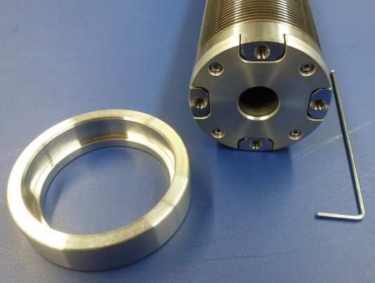
Series 670

Contents
             1    Description of product ........................................................................ 4
                  1.1     Identification of product ................................................................................................... 4
                  1.2     Use of product ................................................................................................................. 4
                  1.3     Used abbreviations .......................................................................................................... 4
                  1.4     Related documents.......................................................................................................... 4
                  1.5     Important information....................................................................................................... 4
                  1.6     Technical data ................................................................................................................. 4

             2    Safety ................................................................................................... 5
                  2.1     Compulsory reading material ........................................................................................... 5
                  2.2     Danger levels .................................................................................................................. 5
                  2.3     Personnel qualifications................................................................................................... 6
                  2.4     Safety labels .................................................................................................................... 6

             3    Design and Function ........................................................................... 7
                  3.1     Design ............................................................................................................................. 7
                  3.2     Function........................................................................................................................... 7

             4    Installation ........................................................................................... 8
                  4.1     Unpacking ....................................................................................................................... 8
                  4.2     Installation into the system .............................................................................................. 9
                          4.2.1      Installation space condition ............................................................................... 9
                          4.2.2      Installation overview ........................................................................................ 10
                          4.2.3      Installation procedure (mechanical, connection) ............................................. 11
                          4.2.4      Installation procedure (homing)....................................................................... 12
                  4.3     Admissible forces .......................................................................................................... 13

             5    Operation ........................................................................................... 14
             6    Trouble shooting ............................................................................... 15
             7    Maintenance ...................................................................................... 16
                  7.1     Maintenance intervals.................................................................................................... 17
                  7.2     Maintenance procedures ............................................................................................... 17
                          7.2.1   Removing the plate and plate seal replacement ............................................. 18
                          7.2.2   Remove the actuator and replace the bellows feedthrough ............................ 22
                          7.2.3   Mount the actuator .......................................................................................... 28

             8    Repairs ............................................................................................... 31
             9    Dismounting and Storage................................................................. 32
                  9.1     Dismounting .................................................................................................................. 32
                  9.2     Storage .......................................................................................................................... 33

             10   Packaging and Transport ................................................................. 34
                  10.1    Packaging...................................................................................................................... 34
                  10.2    Transport ....................................................................................................................... 35

             11   Disposal ............................................................................................. 36
             12   Spare parts ........................................................................................ 37
             13   Appendix ............................................................................................ 39

1078022EB.DOCX                                       Edition 2021-07-09                                                                                 3/40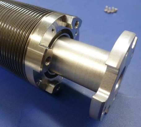
DESCRIPTION OF PRODUCT                                   Series 670

1      Description of product
1.1    Identification of product
       The fabrication number and order fabrication are fixed on the product directly or by means of an
       identification plate.

       made in Switzerland
       Fabrication No.:
            670 . . - . . . . - . . . . / . . . .      Fabrication number
                    A-. . . . . .                      Order number

1.2    Use of product
       Use product for clean and dry vacuum applications only. Other applications are only allowed with the
       written permission of VAT.

1.3    Used abbreviations

       Abbreviation                    Description

       SFV                             Symmetrical flow valve

       CPA                             Control performance analyser

1.4    Related documents

       • Product data sheet
       • Dimensional drawing
       • External controller manual (862870)

1.5    Important information
                                This symbol points to a very important statement that requires particular attention.

       Example:
                                VAT disclaims any liability for damages resulting from inappropriate packaging.

1.6    Technical data
       Please refer to P/N 1078021 Product Data Sheet.

4/40                                                    Edition 2021-07-09                         1078022EB.DOCX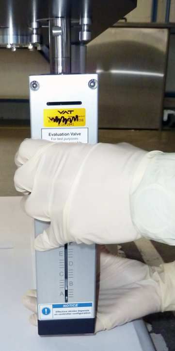
Series 670                                          SAFETY

2            Safety
2.1          Compulsory reading material
             Read this chapter prior to performing any work with or on the product. It contains important information
             that is significant for your own personal safety. This chapter must have been read and understood by
             all persons who perform any kind of work with or on the product during any stage of its serviceable
             life.

                                                                NOTICE
                            Lack of knowledge
                            Failing to read this manual may result in property damage.
                            Firstly, read manual.

                            These Installation, Operating & Maintenance Instructions are an integral part of a
                            comprehensive documentation belonging to a complete technical system. They must
                            be stored together with the other documentation and accessible for anybody who is
                            authorized to work with the system at any time.

2.2          Danger levels

                                                                 DANGER
                            High risk
                            Indicates a hazardous situation which, if not avoided, will result in death or serious
                            injury.

                                                                 WARNING
                            Medium risk
                            Indicates a hazardous situation which, if not avoided, could result in death or serious
                            injury.

                                                                 CAUTION
                            Low risk
                            Indicates a hazardous situation which, if not avoided, may result in minor or moderate
                            injury.

                                                                NOTICE
                            Command
                            Indicates a hazardous situation which, if not avoided, may result in property damage.

1078022EB.DOCX                                Edition 2021-07-09                                                 5/40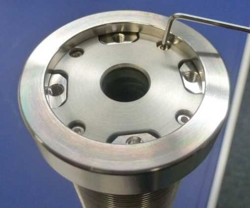
SAFETY                                               Series 670

2.3    Personnel qualifications

                                                     WARNING
                  Unqualified personnel
                  Inappropriate handling may cause serious injury or property damage.
                  Only qualified personnel are allowed to carry out the described work.

2.4    Safety labels

        Label                         Part No.                          Location on valve

                                                                        On protective foil covering the
                                      T-9001-156
                                                                        valve opening

6/40                               Edition 2021-07-09                               1078022EB.DOCX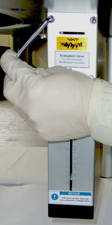
Series 670                               DESIGN AND FUNCTION

3            Design and Function
3.1          Design

                   1      2                3                                4     5

                                                                                                          6

                                                                                                          7

                                                                                                          8

             Sample picture

             1    Flange seal (customer side)     6    Intermediate piece
             2    Plate screw                     7    Actuator shaft with bellows
             3    Plate                           8    Actuator (stepper motor)
             4    Plate seal                           Valve seat side
             5    Flange

3.2          Function
             The valve plate (3) acts as a throttling element and varies the conductance of the valve opening. The
             controller calculates the required plate position to achieve the set point pressure. Actuation is
             performed by two synchronous stepper motors (8). Encoders monitor the position. This principle
             ensures fast and accurate process pressure control.

1078022EB.DOCX                                 Edition 2021-07-09                                             7/40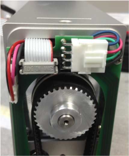
INSTALLATION                                               Series 670

4      Installation

                                                       WARNING
                   Unqualified personnel
                   Inappropriate handling may cause serious injury or property damage.
                   Only qualified personnel are allowed to carry out the described work.

4.1    Unpacking

                                                        WARNING
                   Heavy weight
                   Physical overstraining.
                   Use a crane to lift valves DN 200 (8”) and larger.

                                                       NOTICE
                   Physical overstraining at actuators
                   Inappropriate handling with the valve may cause in damage of actuator.
                   Do not place the valve on the actuators.

                   • Make sure that the supplied products are in accordance with your order.

                   • Inspect the quality of the supplied products visually. If it does not meet your
                     requirements, please contact VAT immediately.

                   • Store the original packaging material. It may be useful if products must be returned
                     to VAT.

       1.

8/40                                Edition 2021-07-09                                 1078022EB.DOCX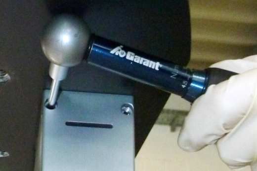
Series 670                                   INSTALLATION

4.2          Installation into the system

                                                               CAUTION
                          Valve opening
                          Risk of injury.
                          Do not connect the controller to power before the valve is installed complete into the
                          system.

                                                              NOTICE
                          Wrong connection
                          Wrong connection may result in damage of controller or power supply.
                          Connect all cables exactly as shown in the following schematic.

                                                              NOTICE
                          Burned connector pins (spark)
                          Connector pins or electronic parts could damage, if plugged and unplugged under
                          power.
                          Do not plug or unplug connectors under power.

                                                              NOTICE
                          Contamination
                          Gate and other parts of the valve must be protected against contamination.
                          Always wear clean room gloves when handling the valve.

                          • Make sure that the sealing surfaces of the valve and the chamber are undamaged.

                          • Mount valve to a clean system only.

4.2.1        Installation space condition

                         Install the valve with actuators with space for dismantling and air circulation as shown
                         in figure below. (sample picture)

1078022EB.DOCX                             Edition 2021-07-09                                                  9/40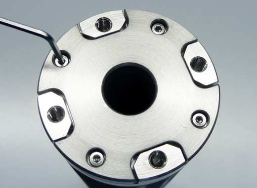
INSTALLATION                                        Series 670

4.2.2   Installation overview

                                 Chamber

                                                                  Symmetrical flow valve [1]

                                Pump side

                             Actuator cables [2]

                                                   External Controller (3)

            Sample picture

10/40                                Edition 2021-07-09                           1078022EB.DOCX
Series 670 INSTALLATION
4.2.3 Installation procedure (mechanical, connection)
All numbers in brackets refer to chapter «Installation overview».
1. Remove protective covers from body flanges.
2. Install symmetrical flow valve [1] into the vacuum system..
• Do not tighten the flange screws stronger than indicated under «Tightening
torque».
• Do not admit higher forces to the valve than indicated under «Admissible forces».
• Make sure that enough space is kept free to do preventive maintenance work. The
required space is indicated on the dimensional drawing
3. Install actuator cables [2] to actuators and then to the External Controller [3]. Refer to chapter
«Installation overview».
4. Install all electrical connections at External Controller. Refer to «External Controller manual».
5. This valve may optionally be equipped with a heating device. Connect VAT heating device
according to manual of respective heating device.
1078022EB.DOCX Edition 2021-07-09 11/40INSTALLATION Series 670
6.
4.2.4 Installation procedure (homing)
Description Required tool
1. Mount the valve and all required
components
2. Switch ON the power supply.
3. If the valve does not start the
homing procedure automatically
(depends on valve setting), initiate
homing procedure manually: Valve
> Parameters > System > Control
Mode = [Homing], press save
button or [Enter] on keyboard.
CPA
4. Wait until Homing is finished. The
position of valve is now 20% open.
The SFV Axis Initialization
Mode will be automatically
disabled after the homing!
5. Valve is ready for use.
Make sure that nothing is
limiting the full stroke of the valve plate
movement!
NOTICE
Physical overstraining at valve flange.
Physical overstraining may cause in damage of valve flange.
Do force (fasten) the screws more as specified by the screw manufacturer.
7.
12/40 Edition 2021-07-09 1078022EB.DOCXSeries 670 INSTALLATION
4.3 Admissible forces
Forces from evacuating the system, from the weight of other components, and from
baking can lead to deformation and malfunctioning of the valve. Stress has to be
relieved by suitable means, e.g. bellows sections.
Axial tensile or
compressive force Bending moment «M» M
«FA»
N lb. Nm lbf.
4000 880 160 120
FA
For a combination of both forces (FA and M) the values are invalid.
Verify that the depth of the mounting screws is min. 1x thread diameter.
Please contact VAT for more information.
8.
9.
1078022EB.DOCX Edition 2021-07-09 13/40OPERATION Series 670
5 Operation
WARNING
Unqualified personnel
Inappropriate handling may cause serious injury or property damage.
Only qualified personnel are allowed to carry out the described work.
CAUTION
Valve opening
Risk of injury.
Do not operating before the valve is installed complete into system.
For «Operation» refer to «External Controller manual».
14/40 Edition 2021-07-09 1078022EB.DOCXSeries 670 TROUBLE SHOOTING
6 Trouble shooting
For «Trouble shooting » refer to «External Controller manual» 907203EB.
If you need any further information, please contact one of our service centers. You can find the
addresses on our website: www.vatvalve.com.
1078022EB.DOCX Edition 2021-07-09 15/40MAINTENANCE Series 670
7 Maintenance
WARNING
Unqualified personnel
Inappropriate handling may cause serious injury or property damage.
Only qualified personnel are allowed to carry out the described work.
CAUTION
Hot surfaces
Heated valve may result in minor or moderate injury.
Do not touch valve and heating device during operation. Once heating is switched off
(valve and system) await until the valve is cooled down complete before doing any
work.
CAUTION
Valve opening
Risk of injury.
Human body parts must be kept out of the valve opening and away from moving parts.
NOTICE
Contamination
Gate and other parts of the valve could be contaminated.
Always wear cleanroom gloves when handling the valve.
NOTICE
Scratches on sealing surface
Scratches on sealing surface cause in malfunction (leak) of valve
Only qualified personnel are allowed to carry out the described work.
16/40 Edition 2021-07-09 1078022EB.DOCXSeries 670 MAINTENANCE
7.1 Maintenance intervals
Under clean operating conditions, the valve does not require any maintenance during the specified
cycle life. Contamination from the process may influence the function and requires more frequent
maintenance.
Before carrying out any maintenance, please contact VAT. It has to be individually decided whether
the maintenance can be performed by the customer or has to be carried out by VAT
www.vatvalve.com. The fabrication number on the valve has always to be specified. Refer to chapter
«1.1 Identification of product» for fabrication number.
7.2 Maintenance procedures
• Open / close the service cover and valve cleaning. Refer to manual of customized process
chamber.
This task is described on customer side.
CPA 4.0 is integrated in the controller. Please following the instruction for installation.
• Removing the plate and plate seal replacement. Refer to chapter «7.2.1 Removing the plate and
plate seal replacement».
• Replace the actuator shaft. Refer to chapter «7.2.2 Remove the actuator and replace the bellows
feedthrough».
1078022EB.DOCX Edition 2021-07-09 17/40MAINTENANCE Series 670
7.2.1 Removing the plate and plate seal replacement
7.2.1.1 Required tools
• Allen wrench 5 mm • Cleanroom wiper
• O-ring removal tool • Isopropyl alcohol
• CPA 4.0 (in EC2 integrated) • Clean room gloves
Electrical power is required.
Description Required tool
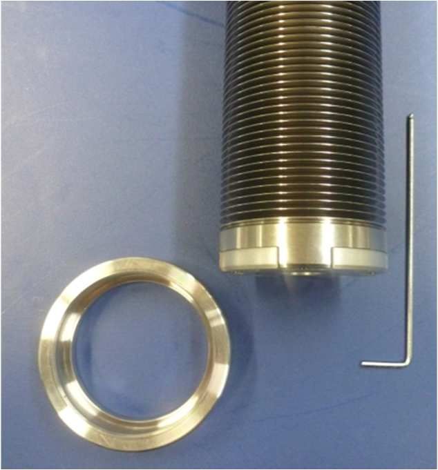
Use the CPA 4.0 which is
integrated in the EC2 controller. CPA
1. Go to [LOCAL] mode.
2. Select position [20] = 20 % open. CPA
If PFO available on EC2
controller, proceed here,
if not go to next step.
CPA
3. Disable the PFO in menu: Valve >
Parameters > Power Fail Option >
Enable = [False], press save button
or [Enter] on keyboard.
18/40 Edition 2021-07-09 1078022EB.DOCXSeries 670 MAINTENANCE
Description Required tool
4. Switch OFF the power supply
Sample pictures…
Allen wrench 5
5. Loosen the 8 plate screws at the mm
Service port and demount the
Service port.
Sample pictures…
Allen wrench 5
6. Loosen the plate screws at plate mm
complete. Do not remove the
screws.
7. Hold the plate by hand. Lift the
plate and turn the Arms carefully in
a line towards the service port and
remove the plate from chamber.
Take care to sealing surface
and valve surface.
8. Place the plate (seal side up) on a • O-ring
clean surface. removal tool
9. Remove the seal. • Cleanroom
wiper
10. Clean plate and the seal groove. • Isopropyl
11. Install the new seal equally around alcohol
360° in seal groove.
• Cleanroom
wiper
12. Clean the internal valve
• Isopropyl
alcohol
1078022EB.DOCX Edition 2021-07-09 19/40MAINTENANCE Series 670
Description Required tool
13. Install the plate in valve as shown in
picture. Allen wrench 5
mm
14. Tighten the plate screws with 8 Nm
Sample pictures…
Allen wrench 5
mm
15. Install the service port and tighten
the 8 plate screws wit 6 Nm.
16. Switch ON the power supply.
17. Select [LOCAL] CPA
If PFO available on EC2
controller, proceed here,
if not go to next step.
18. Enable the PFO in menu: Valve >
Parameters > Power Fail Option >
Enable = [TRUE], press save
button or [Enter] on keyboard
20/40 Edition 2021-07-09 1078022EB.DOCXSeries 670 MAINTENANCE
Description Required tool
19. Select [CLOSE], the valve is
executing Homing and moves to CPA
close position.
20. Close the service cover. Refer to
manual of customized process
chamber.
21. Valve is ready for use.
1078022EB.DOCX Edition 2021-07-09 21/40MAINTENANCE Series 670
7.2.2 Remove the actuator and replace the bellows feedthrough
7.2.2.1 Required tools
• Allen wrench 2.5 mm • Pozidriv screwdriver No.1
• Allen wrench 3 mm • CPA 4.0 (in EC2 integrated)
• Allen wrench 4 mm
Electrical power is required.
Remove the actuator
Description Required tool
22. Use the description of chapter
«7.2.1 Removing the plate and
plate seal replacement to remove
the plate. Only steps for removing
are needed.
21. Place the plate on a clean surface.
22. Switch ON the power supply.
23. Select [LOCAL]. CPA
24. Enter the SFV Axis Initialization
Mode: Parameters > Valve > SFV
Axis Initialization Mode > True,
press save button or [Enter] on
keyboard
25. Switch OFF the power supply.
22/40 Edition 2021-07-09 1078022EB.DOCXSeries 670 MAINTENANCE
Description Required tool
Pozidriv
26. Disconnect the power cable
screwdriver No.1
Take care to sealing surface
of flange and actuator.
27. Loosen the actuator screws (white
arrows) complete and remove the Allen wrench
actuators. 4mm
Make sure that the actuator not
dropdown. Hold the actuator
with the second hand.
1078022EB.DOCX Edition 2021-07-09 23/40MAINTENANCE Series 670
Description Required tool
Take care to sealing surface
and valve surface
28. Remove the actuator
Replace the bellows
Description Required tool
29. Loosen the cover screw.
30. Remove the cover of actuator.
Allen wrench 3
mm
Take care to cables.
Allen wrench 3
31. Loosen these 4 screws complete.
mm
24/40 Edition 2021-07-09 1078022EB.DOCXSeries 670 MAINTENANCE
Description Required tool
Allen wrench 2.5
32. Loosen and remove these 2 screws
mm
33. Remove the bellows complete
Take care to surface of
actuator and bellows complete.
34. Take the adjusting ring
Allen wrench 1.5
35. Loosen and remove all 4 screws.
mm
1078022EB.DOCX Edition 2021-07-09 25/40MAINTENANCE Series 670
Description Required tool
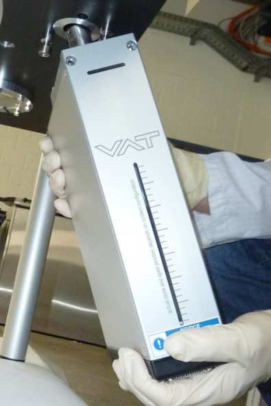
36. Remove the shaft and install the
new one
Adjusting ring
579811
37. Fasten the 4 screws by hand with
the adjusting ring
Allen wrench 1.5
mm
38. Remove the adjusting ring
39. Install new bellows complete in
actuator. For new bellows complete
refer to chapter: «Spare parts».
Take care to surface of
actuator and bellows complete.
Do not scratch the bellows at
actuator surface!
26/40 Edition 2021-07-09 1078022EB.DOCXSeries 670 MAINTENANCE
Description Required tool
40. Fasten the 4 screws by hand with
Allen wrench 3 mm. Allen wrench 3
mm
41. Now fasten the 4 screws crosswise
with 4 Nm
42. Close the actuator cover
Take care to the cables
Do not jam the cables!
Allen wrench 3
43. Fasten the cover screw adequately
mm
Allen wrench 2.5
44. Fasten these 2 screws adequately
mm
1078022EB.DOCX Edition 2021-07-09 27/40MAINTENANCE Series 670
7.2.3 Mount the actuator
7.2.3.1 Required tools
• Allen wrench 2.5 mm • Pozidriv screwdriver No.1
• Allen wrench 3 mm • CPA 4.0 (in EC2 integrated)
• Allen wrench 4 mm
Electrical power is required.
Take care to sealing surface
and valve surface
45. Insert the new actuator
Allen wrench
46. Fasten the actuator screws by hand
4mm
28/40 Edition 2021-07-09 1078022EB.DOCXSeries 670 MAINTENANCE
Allen torque
47. Fasten the actuator screws with
wrench
8Nm
4mm
48. Connect the power cables
Take care to the connector Pozidriv
position at actuators, refer to screwdriver No.1
3 dots at connector for
correct connection.
The plate is not installed for
the next steps!
49. Switch ON the power supply.
50. If the valve does not start the
homing procedure automatically
(depends on valve setting), initiate
homing procedure manually: Valve
> Parameters > System > Control
Mode = [Homing], press save
button or [Enter] on keyboard.
CPA
51. Wait until Homing is finished. The
position of valve is now 20% open.
The SFV Axis Initialization
Mode will be automatically
disabled after the homing!
52. Switch OFF the power supply.
53. Install the plate, refer to chapter:
«7.2.1 Removing the plate and
plate seal replacement.
1078022EB.DOCX Edition 2021-07-09 29/40MAINTENANCE Series 670
54. Select [CLOSE], the valve is
executing Homing and moves to CPA
close position.
55. Close the service cover. Refer to
manual of customized process
chamber.
56. Valve is ready for use.
30/40 Edition 2021-07-09 1078022EB.DOCXSeries 670 REPAIRS
8 Repairs
Repairs may only be carried out by the VAT service staff. In exceptional cases, the customer is
allowed to carry out the repairs, but only with the prior consent of VAT.
Please contact one of our service centers. You will find the addresses on our website
www.vatvalve.com.
1078022EB.DOCX Edition 2021-07-09 31/40DISMOUNTING AND STORAGE Series 670
9 Dismounting and Storage
WARNING
Unqualified personnel
Inappropriate handling may cause serious injury or property damage.
Only qualified personnel are allowed to carry out the described work.
9.1 Dismounting
NOTICE
Contamination
Gate and other parts of the valve could be contaminated.
Always wear clean room gloves when handling the valve.
NOTICE
Valve in open position
Valve body may become damaged if valve gate is in open position.
Move valve gate to the closed position before dismounting the valve.
1. Close the valve.
2. For dismounting the valve please follow the instructions of chapter «Installation», however in
reverse order.
32/40 Edition 2021-07-09 1078022EB.DOCXSeries 670 DISMOUNTING AND STORAGE
9.2 Storage
NOTICE
Wrong storage
Inappropriate temperatures and humidity may cause damage to the product.
Valve must be stored at:
– relative humidity between 10% and 70%
– temperature between +10 °C and +50 °C
– non-condensing environment
NOTICE
Inappropriate packaging
Product may get damaged if inappropriate packaging material is used.
Always use the original packaging material and handle product with care.
1. Clean / decontaminate valve.
2. Cover all valve openings with a protective foil.
3. Pack valve appropriately, by using the original packaging material.
1078022EB.DOCX Edition 2021-07-09 33/40PACKAGING AND TRANSPORT Series 670
10 Packaging and Transport
WARNING
Unqualified personnel
Inappropriate handling may cause serious injury or property damage.
Only qualified personnel are allowed to carry out the described work.
WARNING
Harmful substances
Risk of injury in case of contact with harmful substances.
Remove harmful substances (e. g. toxic, caustic or microbiological ones) from valve
before you return the valve to VAT.
NOTICE
Inappropriate packaging
Product may get damaged if inappropriate packaging material is used.
Always use the original packaging material and handle product with care.
When returning products to VAT, please fill out the VAT form «Declaration of
Chemical Contamination» and send it to VAT in advance. The form can be
downloaded from our website www.vatvalve.com.
• If products are radioactively contaminated, the VAT form «Contamination and
Radiation Report» must be filled out. Please contact VAT in advance.
• If products are sent to VAT in contaminated condition, VAT will carry out the
decontamination procedure at the customer's expense.
10.1 Packaging
1. Cover all valve openings with a protective foil.
2. Pack valve appropriately, by using the original packaging material.
VAT disclaims any liability for damages resulting from inappropriate packaging.
34/40 Edition 2021-07-09 1078022EB.DOCXSeries 670 PACKAGING AND TRANSPORT
10.2 Transport
NOTICE
Inappropriate packaging
Product may get damaged if inappropriate packaging material is used.
Always use the original packaging material and handle product with care.
VAT disclaims any liability for damages resulting from inappropriate packaging.
1078022EB.DOCX Edition 2021-07-09 35/40DISPOSAL Series 670
11 Disposal
WARNING
Harmful substances
Environmental pollution.
Discard products and parts according to the local regulations.
36/40 Edition 2021-07-09 1078022EB.DOCXSeries 670 SPARE PARTS
12 Spare parts
NOTICE
Non-original spare parts
Non-original spare parts may cause damage to the product.
Use original spare parts from VAT only.
• Please specify the fabrication number of the product when you place an order for
spare parts; see chapter «1.1 Identification of product». This is to ensure that the
appropriate spare parts are supplied.
• VAT makes a difference between spare parts that may be replaced by the
customer and those that need to be replaced by the VAT service staff.
• The following table(s) only contains spare parts that may be replaced by the
customer. If you need any other spare parts, please contact one of our service
centers. You will find the addresses on our website www.vatvalve.com.
Item Description Part number
Actuator complete (2 x) 926607
Bellows complete (2 ×) 890901
Actuator seal (2 x) 889748
(60) Actuator mounting pin (4 x) 892041
1078022EB.DOCX Edition 2021-07-09 37/40SPARE PARTS Series 670
Item Description Part number
(70) Intermediate peace (2 x) 888957
(110) Actuator circle (2x) 892461
(110) Plate seal 889746
(210) Pump ring screw seal (6 x) 889744
(220) Pump ring seal 889745
(200) Service port seal 889743
38/40 Edition 2021-07-09 1078022EB.DOCXSeries 670 13 Appendix 1078022EB.DOCX Edition 2021-07-09 39/40
Series 670

        This Page Intentionally Left Blank

40/40         Edition 2021-07-09             1078022EB.DOCX
You can also read