INTRODUCTION TO "CLEAN-SLATE" CELLULAR IOT RADIO ACCESS SOLUTION
←
→
Page content transcription
If your browser does not render page correctly, please read the page content below
Introduction to “Clean-Slate”
  Cellular IoT radio access
           solution

                                Page
                                 Page1 1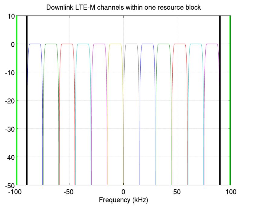
Introduction and motivation
    The Cellular IoT White Paper demonstrates that there is a huge opportunity for Mobile Network
    Operators to exploit the emerging IoT market

    However, this opportunity is critically dependent on achieving the following:
            Ultra-low cost terminals (module cost less than $5)
            Battery life of > 10 years (assuming 100 bytes/hour uplink)
            20 dB extended link budget versus existing cellular technologies to ensure reliable coverage into
            difficult locations
    An inability to meet these objectives will result in much of the potential market for Cellular IoT being
    absorbed by alternative technologies such as WiFi, Zigbee, Bluetooth Smart and proprietary systems

    Although an evolution of LTE might appear initially attractive due to a convenient standardisation
    path, it will most likely prove impossible to meet these objectives
            This is simply due to the inevitable overheads and inefficiencies that will result from trying to adapt a
            very high data rate broadband delivery system to support low data rate IoT applications

What is needed is an optimised solution for Cellular IoT that can be deployed using existing cellular
infrastructure, and which is superior to alternative technologies for a large segment of IoT applications

                                                                                                           Page
                                                                                                            Page22
Key features of clean-slate solution
IoT network can be deployed in a very small bandwidth (180 kHz downlink, 180 kHz uplink)
Offers a wide range of deployment options, whilst supporting a huge number of terminals per cell
(tens of thousands)
Modulation methods chosen specifically to minimise potential coexistence issues with technologies
operating at adjacent frequencies
Optimized for ultra-low terminal cost (< $5)
Designed from the ground-up to deliver the required performance for IoT at very low cost
Removes unnecessary complexity that is not required for IoT applications
Simple air-interface should greatly reduce potential IPR licensing costs
No cost overhead due to legacy
Optimised for very long terminal battery life (> 10 years)
Efficiently supports very low duty cycle modes, while terminals remain “connected” to network
Supports both scheduled and event driven traffic
Single-carrier modulation allows high efficiency, high power transmitters (similar to GPRS)
Extended coverage compared with existing cellular (20 dB enhancement)
Supports higher data rates where path loss permits, but can configure cell-edge terminals for much
lower data rates to increase processing gain and hence improve link budget
Page
Page33Downlink channelization
Each 180 kHz resource block is split into 12 downlink
channels, spaced by 15 kHz
Allows access through FDMA and TDMA
One downlink channel is reserved for synch /
1 2 3 4 5 6 7 8 9 10 11 12 broadcast for efficient network acquisition
Each basestation sector can be assigned a subset of
downlink channels
Supports flexible frequency re-use
Allows frequency diversity through frequency
hopping
Downlink channels are individually modulated and pulse-
shaped to minimise spectral side-lobes
Reduces coexistence issues with adjacent
systems
Receiver equalisation is simple (single-carrier,
with low bandwidth)
3 dB bandwidth for each channel is 12 kHz
Modulation is 16QAM, QPSK and BPSK
Spreading / repetition for processing gain
Coding is convolutional to minimise terminal
receiver complexity
Page
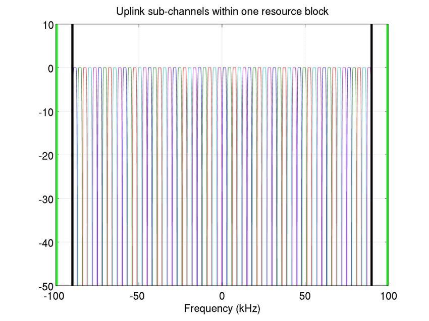
Page44Uplink channelization
Each 180 kHz resource block is split into many uplink
channels
Allows access through FDMA and TDMA
Provides high uplink capacity and very flexible
Uplink channels frequency re-use
Uplink channels are individually modulated and pulse-
shaped to minimise inter-user interference
Avoids feedback loops for frequency correction or
timing advance, unlike OFDMA or SC-FDMA
3 dB bandwidth for each channel is 2 kHz or 3.75 kHz
Modulation is (D)QPSK, (D)BPSK or GMSK
Very low or zero PAPR, for high transmitter
efficiency (similar to GPRS/EDGE)
Spreading / repetition for processing gain
Coding is convolutional or turbo, depending on
burst type
Uplink channels may be bonded by x2, x4 or x8
Still single-carrier, but provides higher uplink data
rates when path loss permits
Maximum uplink data rate is 45 kbps, minimum uplink data
rate is 250 bps
Page
Page55Deployment in GSM sub-carrier
Licensed by Mobile Network Operator (e.g. GSM850 or GSM900)
M2M network is deployed
in a single re-farmed GSM
sub-carrier
Each single-carrier is
Power
Multiple GSM sub-carriers, with 200 kHz spacing
individually pulse-shaped
to avoid spectral spillage
Can also be deployed
in left-over spectrum
following 2G/3G re-
farming
Frequency
Implemented as FDD, i.e. with M2M downlink in GSM downlink sub-carrier group
Single-carrier, pulse-shaped modulation avoids spectral side-lobes so minimises co-existence issues
Page
Page66Deployment in LTE guard bands
Licensed by Mobile Network Operator in LTE700, LTE800 or LTE900
9MHz occupied by OFDM Resource Elements
LTE in adjacent
channel
M2M network is
deployed in LTE
Power
guard bands
LTE Physical Resource Blocks
(50 PRB x 180 kHz in 10 MHz) Each single carrier
is individually pulse-
shaped to avoid
spectral spillage
Use of both guard
bands provides
frequency diversity
-5 -4.5 0 +4.5 +5
Frequency (MHz)
Implemented in LTE-FDD, i.e. with M2M downlink in LTE downlink guard bands
Co-existence examined in detail and effective mitigation strategies available
Page
Page7720 dB coverage enhancement
Downlink Uplink
Simulation parameters:
Transmitter
Uplink: GMSK modulation, 1/3 code rate Turbo coding,
(0) Max Tx power (dBm) 46 23
80 ms frame length, x8 repetition, 1T2R
(1) Actual Tx power (dBm) 35.2 23
Downlink: QPSK modulation, 1/3 code rate Turbo coding,
Receiver 25 ms frame length, x8 spreading factor + x2 repetition, 2T1R
(2) Thermal noise density (dBm/Hz) -174 -174
Downlink simulation results Uplink simulation results
(3) Receiver noise figure (dB) 9 5 10
0 10
0
(4) Interference margin (dB) 0 0
(5) Occupied channel bandwidth (kHz) 12 3.75 -2.8dB -6dB
BLER
BLER
-1 -1
10 10
(6) Effective noise power
-124.2 -133.3
= (2) + (3) + (4) + 10 log((5)) (dBm)
-2 -2
(7) Required SINR (dB) -2.8 -6 10
-10 -8 -6 -4 -2 0 2
10
-10 -9 -8 -7 -6 -5 -4 -3
Eb/No (dB) Eb/N0 (dB)
(8) Receiver sensitivity
-127 -139.3
= (6) + (7) (dBm) Graphs show SNR threshold for 10% BLER using EPA1Hz
Maximum coupling loss (MCL) channel with 100 Hz residual frequency offset
162.2 162.3
= (1) – (8) (dB)
20 dB coverage enhancement is achieved versus LTE/GSM
(according to 3GPP 36.888, the maximum coupling loss is 140.7 dB for LTE, and is 139.4 dB for GSM)
Page
Page88Cell capacity analysis
Served uplink users per hour per 180 kHz
Shows number of users served with 100 byte
x1000 uplink payload per 180 kHz per hour
Includes 30% overheads for uplink
Assumes 15 uplink channels (so frequency re-
use is ¼ to mitigate inter-cell interference)
3GPP case 3 Terminal transmit power is +23 dBm with
-4 dB antenna gain
Base station noise figure is 4 dB with +14 dB
antenna gain
Path loss = 120.9 + 37.6 log10(Rkm), plus log-
1732m ISD
normal fading with 8 dB sigma
3GPP case3 + 20dB Curves show additional 0, 20, 30 and 40 dB
penetration/path loss (3GPP case3
corresponds to 20 dB curve)
Excludes out-of-range terminals
Page
Page99Cell coverage analysis
Percentage users that can be reached
Percent
Shows percentage of terminals that can be
reached, assuming uniform density
Modelling assumptions are the same as for
3GPP case 3 the Cell Capacity Analysis slide
Minimum uplink data rate is set as:
250 bps = 32 bytes/sec
(raw PHY rate after FEC)
3GPP case3 + 20dB
~20 bytes/sec after overheads
1732m ISD
Terminals that cannot support this minimum
data rate are considered to be not covered
Page
Page1010Power consumption analysis
Battery life for 2500 mAh x 3.7V capacity Assumptions:
Report = 100 bytes uplink, 20 bytes downlink 3GPP traffic model
Coverage +23 dBm transmission power with x8 spreading /
enhancement 6 reports/hour 1 report/hour 1 report/day repetition for 20 dB enhanced coverage
vs. GSM +13 dBm transmission power with no spreading /
repetition for 0 dB enhanced coverage
GSM + 0 dB 6.7 years > 20 years > 20 years
Battery self-discharge is not included
GSM + 10 dB 3.0 years 14.7 years > 20 years
GSM + 20 dB 0.4 years 2.3 years > 20 years
Assumptions
GSM coverage
Voltage Tx 23dBm Tx 13dBm Rx Idle/sleep
(V) (mA) (mA) (mA) (uA) GSM coverage + 10dB
GSM coverage + 20dB
3.3 190 80 20 5
Battery life of > 10 years for terminals that require up to 10 dB coverage enhancement
versus GSM, for hourly reporting
Battery life will be < 10 years for terminals that require > 10 dB coverage enhancement
versus GSM, for hourly reporting, so longer report period may need to be considered
Page
Page1111Coexistence with GSM 0
-10
-20
Benefits of using narrow signal bandwidths
to improve coexistence: -30
dBc
Up-sampling in digital domain can be -40
used to perform pulse shaping and
-50
digital filtering
Multi-stage digital filter reduces the side- -60
lobes and images of the spectrum -70
1.7 1.75 1.8 1.85 1.9 1.95 2 2.05
Far-out from the narrow band signal is Hz
x 10
5
below -70dBc, so meets the GSM 0
GSM Spectrum Mask
spectrum mask -10
Clean-Slate Celluar IoT Spectrum
-20
Only a marginal GSM performance loss is Narrow band signal
-30 spectrum simulation
introduced due to interference from Clean-
dBc
with PA
Slate Cellular IoT waveforms -40
Performance loss is < 1 dB -50
Based on both link simulations and -60
system simulations
-70
0 2 4 6 8 10 12
Hz 5
x 10
Page
Page1212Module cost analysis
eBOM 2016 Estimates Module ASP estimate is for 2016
Single chip RF/BB $ 0.95
16Mb NOR flash $ 0.20
(excludes IPR licensing – should be modest)
PA/switch module $ 0.50
26MHz XO $ 0.20
Single-chip RF/BB IC
32kHz XO $ 0.12
RF filter $ 0.15 Area estimate (excl. scribe & seal):
Other discretes $ 0.25 9.2 mm2 on 90nm
Total eBOM $ 2.37 7.0 mm2 on 65nm
Mechanical, Assembly & Test
PCB (4 layer FR4, 175mm2) $ 0.13
Assumed functionality includes:
Shield $ 0.04 700-960 MHz transceiver
Assembly $ 0.45 Integrated power management from
Test $ 0.10 battery
Yield loss (2%) $ 0.06 DSP core for software defined
Packaging/labelling $ 0.10 modem, plus custom digits for
CEM margin (5%) $ 0.17 filtering and accelerators
Total ex-works price $ 3.43
ARM M0 core for protocol stack and
OEM value-added
space for 3rd party application code
Freight (shipped) $ 0.20
Allowance for swap/RMA (2%) $ 0.07
OEM margin (10%) $ 0.37 Module ASP is ~ $4 excluding licensing,
Total expense to MNO or VAR $ 4.07 so will be significantly below $5 target
Page
Page1313Approach to standardisation and roadmap
R13
New Radio I/F
3GPP
R13/R14
Evolved Core
1st Commercial
Network Network
Devices
Samples Commercial
2014 2015 2016 2017
Page
Page1414Summary
The proposed clean-slate radio access technology offers substantial benefits:
IoT network can be deployed in a very small bandwidth (DL: 180 kHz, UL: 180kHz)
Optimized for ultra-low terminal module cost (< $5)
Optimised for very long terminal battery life (> 10 years)
Extended coverage compared with existing cellular (20 dB enhancement)
These benefits are very hard to achieve through the evolution of existing cellular radio
access technologies
Because the IoT requirements are so different from mobile broadband
Deployment options include re-farming of GSM sub-carriers, LTE guard bands, and left-
over fragments of spectrum during re-farming of 2G/3G to 4G
Page
Page1515You can also read