IUVA News - Focus on UV LEDs n Disinfection 101 n Design Considerations n Water Treatment n Devices and Systems
←
→
Page content transcription
If your browser does not render page correctly, please read the page content below
IUVANews
Vol. 20, Issue 1 · 2018 Quarter 1

 Focus on UV LEDs
 n   Disinfection 101
 n   Design Considerations
 n   Water Treatment
 n   Devices and Systems

           Official Publication of the International Ultraviolet Association
Contents                            2018 Quarter 1

Features                                                                                           Departments
4		 UV LED Disinfection 101                                                                         2 President’s Letter
		    by Sara Beck, Eawag                                                                           2 From the
                                                                                                   		Associate Editor
10    Design Considerations for Creating an Optimized UV LED System                                30 UV Industry News
		    by Brian Jasenak, Kopp Glass Inc.
                                                                                                   32 Calendar
14    UV LED Technology: The Times They are A-Changin’                                             32 Ad Index
		    by Fariborz Taghipour, University of British Columbia

18    UV LEDs for Water Treatment: Research Overview & Perspective
		    by Kumiko Oguma, University of Tokyo

22    UV-C LED Devices and Systems: Current and Future State
		    by Oliver Lawal, Jim Cosman and Dr. Jennifer Pagan, AquiSense Technologies LLC

29 IUVA Task Force for the Development of UV-C LED
		   Validation Guidelines for Water Treatment

Executive Operating              Editorial Board                      Editor-in-Chief                    Published by:
Committee                        Professor Ezra Cates                 Jim Bolton
                                   Clemson University                 editorinchief@iuva.org
Oliver Lawal                                                                                                     www.petersonpublications.com
                                 Christine Cotton, P.E.
 President                                                            Associate Editor
Jutta Eggers, Ph.D.               ARCADIS                                                                2150 SW Westport Dr., Suite 101
                                                                      Professor Jim Malley
Ian Mayor-Smith                  Samuel S. Jeyanayagam, Ph.D.,                                           Topeka, KS 66614
                                                                      assoceditor@iuva.org
 EMEA Co-Vice Presidents          P.E. BCEE CH2M Hill                                                    785.271.5801
Kumiko Oguma, Ph.D.              Professor James P. Malley, Jr.,      IUVA News (print version)
                                  Ph.D. University of New Hampshire   (ISSN 1528-2017) is published      Managing Editor: Brittany Willes
 Asia Vice President
                                                                      quarterly by the International
Jamal Awad, Ph.D., P.E.          Jennifer Pagan                                                          Graphic Designer: Kelly Adams
                                                                      Ultraviolet Association, Inc.
Chip Blatchley, Ph.D.             Aquisense Technologies              An online version is posted on     Advertising/Sales: Janet Dunnichay
 Americas Co-Vice Presidents     Phyllis B. Posy                      www.iuvanews.com.
Gary Hunter, P.E., Treasurer      Atlantium Technologies                                                 Opinions expressed in this publication
                                 Harold Wright                        IUVA News Editorial Office         may or may not reflect the views of
Ron Hofmann, Ph.D.                                                    628 Cheriton Cres. NW              the Association and do not necessarily
 Secretary and President-Elect     Carollo Engineers
                                                                      Edmonton, AB, Canada T6R 2M5       represent official positions or policies
Kati Bell, Ph.D., P.E.                                                780.439.4709                       of the Association or its members.
 Past President

                                                                                                        2018 Quarter 1                      1
A Message
                                              from the IUVA President
                     Jim Bolton – a name that will always be synonymous with the International Ultraviolet Association and an individual that
                     has showed consistent passion and drive for the development of UV technology. Because of his work and dedication to
                     the IUVA, I am pleased to announce that the IUVA Board unanimously approved the Best Student Paper Award will be
   Oliver Lawal      named in his honor going forward. Thank you, Jim!

I feel invigorated coming off the America’s Conference in Redondo Beach, California, in February. Attendance was up more than 10% from
last year’s event, and the strong program reflected both new and familiar themes. From consensus building on regulatory issues for Ballast
Water and Drinking Water Systems to starting the process for new applications in the prevention of Hospital Acquired Infections (HAI) and the
use of UV-C LED technology, the need is tangible, and our organization is making a difference.

This is a member-driven organization, so I encourage everyone to contribute to the discussion. The 20th anniversary World Congress, to be
held in Sydney, Australia, in early 2019 will come quickly; I encourage all to consider submitting abstracts proposals for topics of discussion,
offering sponsorships and exhibiting new products.

Coming up quickly is the UV LED specialty conference in Berlin, Germany. This will be the most comprehensive global gathering of technical
know-how this exciting new area of technology ever held. Even if you are not directly involved in LED work, I think this issue of IUVA News
will provide some insight into how this might shape our industry in the future and where limitations will apply.

Again, I would encourage everyone to seek opportunities to participate in our various committees, councils and working groups to carry
progress forwards. As always, please do not hesitate to contact me directly with any questions or concerns at oliver.lawal@aquisense.com or
859.869.4700.
Oliver Lawal, IUVA president
President and CEO, AquiSense Technologies

                      A Message
                                               from the Associate Editor
                     As the associate editor for IUVA News, Jim Bolton has asked me to edit this spring 2018 issue. The theme for this issue
                     is UV LEDs and is intended to complement the International Conference on UV LED Technologies & Applications
                     (ICULTA-18) taking place April 22-25, 2018, in Berlin, Germany. Future IUVA News themes will include (summer
    Jim Malley       2018) food and beverages, edited by Jim Bolton; (fall 2018) reuse water, edited by Jim Malley; and (winter 2018) air and
                     surface treatment, edited by Jim Bolton.

This IUVA News issue features five articles, starting with the basics of UV LEDs for disinfection applications followed by articles on
recent trends in UV LEDs and the optimization of UV LED designs. UV LEDs offer several potential advantages over conventional UV
technologies, including mercury-free operation, compact and almost limitless geometric arrangements, instant on/off and unlimited cycling,
neutral temperature impacts, and potential for wavelength specific delivery to achieve specific treatment objectives.

If you would like to submit a paper for the summer 2018 or winter 2018 issues, please send it to Jim Bolton at editorinchief@iuva.org. For the
fall 2018 theme, submit a paper to Jim Malley at jim.malley@unh.edu. The deadlines are May 15 for the summer 2018 issue, July 15 for the
fall 2018 issue and Sept. 15 for the winter 2018 issue.

IUVA News is your quarterly ultraviolet magazine to keep you up to date on what is trending in UV technology and at IUVA, so please take
some time to read it through, and don’t forget the ads. The ads make it possible to publish the magazine, so please support our advertisers
by visiting their websites or contacting them for further information. If you are a marketing manager in a UV company, I encourage you
to advertise. You will not only attract direct sales but also enhance your image in the UV community. Send an email to Jim Bolton at
editorinchief@iuva.org, and we will send you the IUVA News Media Kit.

Also note that IUVA News publishes short Application Notes highlighting novel and ground-breaking applications of a UV company’s
technology. IUVA Corporate Members are welcome to contribute short announcements to the UV Industry News column.
Jim Malley, IUVA News associate editor

     2           IUVA News / Vol. 20 No. 1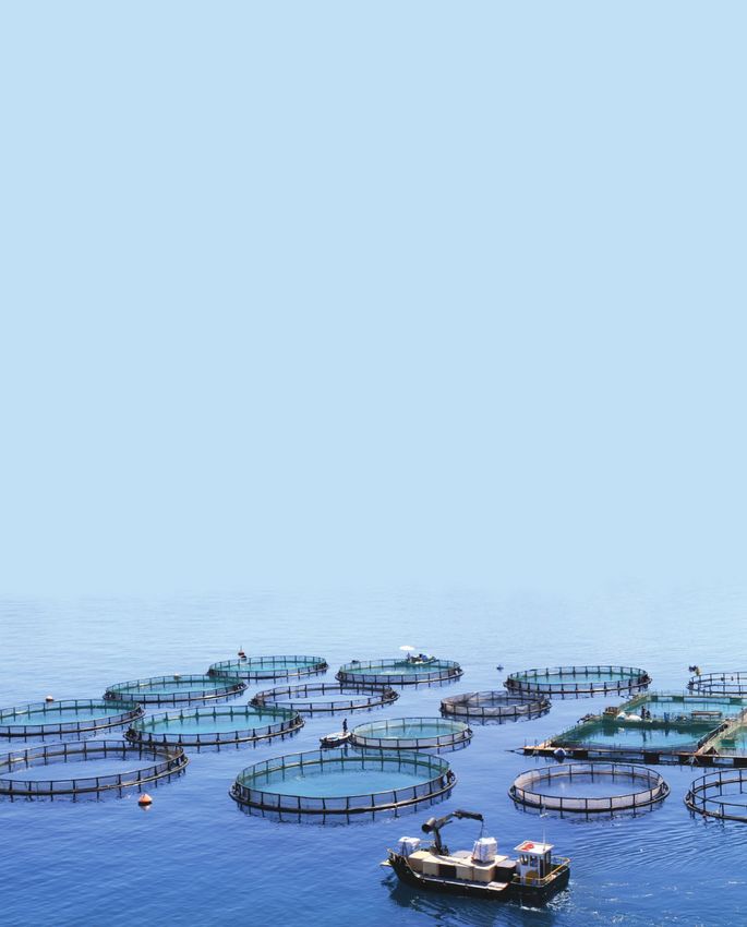
Pure water –
best quality.
Clean water is an essential element of our life.
In order to handle this scarce resource it
becomes even more important to have a reliable
UV solutions partner.

Smart solutions for sustainable disinfection
of drinking water with

  high quality products
  environmentally friendly technology
  low energy consumption

                Because clean water
                is a matter of trust:
                Think UV. Think Heraeus.
Contact us at: hng-uv@heraeus.com
www.heraeus-noblelight.com
UV LED Disinfection 101
Sara Beck, Ph.D.
Eawag – Swiss Federal Institute of Aquatic Science and Technology, Uberlandstrasse 133, 8600 Dubendorf, Switzerland;
contact: +41.58.765.5101 or sara.beck@eawag.ch

Keywords: Ultraviolet, UV, light-emitting diodes (LEDs),            awarded the Nobel Prize in Medicine, set the stage for
disinfection                                                        modern UV systems – used in hospital wards, for example –
                                                                    which prevent the spread of tuberculosis and other airborne
Synopsis                                                            diseases.
Light is fascinating. It can be harnessed by solar panels to
supply electricity to a building; it can be reflected off a land    Before the end of the 19th century, researchers began to
surface to create high-resolution topographical imagery; and        understand the importance of the different wavelength ranges
it can be used to inactivate harmful pathogens and prevent the      of light. Using prisms and colored glass screens to separate
spread of airborne and waterborne diseases. The concept of          sunlight into distinct wavelengths, they showed that the inhi-
using light to kill (or, “inactivate”) a living being is straight   bition of bacteria was wavelength-dependent and caused by
out of science fiction, and yet scientists have been doing it       the blue, violet and ultraviolet (UV) segments of the light
intentionally for public health reasons since the late 1800s.       spectrum (Geisler, 1892; Ward, 1892).

What is ultraviolet disinfection? How has it evolved over           Introducing large-scale UV disinfection of water
time? How can we take advantage of recent advances in the           These first experiments primarily used solar disinfection,
technology to make it even more effective?                          called SODIS, which is used today with plastic bottles as
                                                                    a low-cost water treatment method; however, UV lamps
This article gives a high-level overview of light-based disin-      were not far behind. The first large-scale water disinfection
fection, the evolution of UV technologies over time and the         system (Figure 1) to use UV lamps was set up in 1910 (and
potential of UV light emitting diodes (LEDs), a tiny light          taken down soon thereafter) to treat filtered river water in
source at the tip of our fingers, to transform water disinfec-      Marseilles, France (Henri et al., 1910). Chlorine outpaced
tion and contribute to solving critical public health problems      UV disinfection in the 1920s, so it wasn’t until 1955 that
on a global scale.                                                  large-scale UV systems were consistently operational in
                                                                    Switzerland and Austria (Bolton and Cotton, 2011).
Discovering the bactericidal effects of light
Solar disinfection was first discovered in the mid- to late 19th
century, at a time when contaminated water led to waterborne
disease outbreaks and pandemics across Europe, Asia and the
Americas. Two English scientists investigated the effects of
light on microorganisms in 1877 by exposing test tubes of a
brown sugar solution to sunlight and monitoring for bacte-
rial growth. Within days, bacteria began growing in the
shaded samples, but growth was inhibited for up to a month
in the samples exposed to sunlight. These early experiments
revealed that the disinfection was dependent upon how long
each sample was exposed, as well as the intensity of the
sunlight. (Downes and Blunt, 1877).                                 Figure 1. Schematic of the first large-scale drinking water
                                                                    disinfection system to use UV, in Marseilles, France in 1910
A decade later, while working with bacillus anthracis               (Henri et al. 1910)
(anthrax!) spores and other bacteria, French researchers
discovered that the light sensitivity varied among microor-         In the following decades, UV technology did not change
ganisms (Duclaux, 1885; Arnaud, 1890). This is also when            as much as the reasons for using it. UV was introduced to
the famous German microbiologist and epidemiologist who             Norway in 1975 due to concerns over carcinogenic disin-
developed our standard laboratory practices, Robert Koch,           fection byproducts from chlorination (Paidalwar, A. and
linked the spread of disease to disease-causing microorgan-         Khedikar, I., 2016). At the turn of the century, UV continued
isms called pathogens. Koch was the first to use sunlight           to dominate in Europe for drinking water treatment (Sommer
specifically against tuberculosis (Koch, 1890). His work,           et al., 2002). In the United States, UV was used mainly for

    4        IUVA News / Vol. 20 No. 1
wastewater. That began to change after scientists discovered         tion. UV photons, which are essentially little packets of
that ultraviolet light was not only effective against bacteria and   energy, hit – or are absorbed by – the chemical bonds holding
viruses, it also could prevent the spread of Cryptosporidium         this complex helical structure in place (Figure 2). Bonds are
and Giardia, protozoan pathogens that are highly resistant to        broken; new bonds are formed.
chlorine (Clancy et al., 1998 and Bukhari et al., 1998). By
2006, the U.S. Environmental Protection Agency required a            UV-induced damage to the DNA prevents it from being
secondary barrier, in addition to chlorine, to prevent Crypto-       replicated. As the DNA polymerase enzyme replicates the
sporidium and Giardia outbreaks (USEPA, 2006). This led to           DNA strand, creating a complement, it gets stuck at the site
the largest UV disinfection system in the world, which treats        of damage, kind of like a zipper that gets stuck on a winter
the water for New York City. The Catskill-Delaware UV Water          jacket. The DNA replication cannot be completed. Since the
Treatment Facility, commissioned in 2013, uses a network of          organism cannot reproduce, it cannot infect. Although it has
over 11,000 UV lamps to disinfect 9 billion liters of water          not been killed, per se – it has been rendered inactive. This
daily from the highly protected Catskill and Delaware County         holds true for RNA-based organisms and single-stranded
watersheds (Catskill-Delaware Ultraviolet Water Treatment            DNA and RNA as well.
Facility).
                                                                     Gates used an instrument
Traditional UV lamps                                                 called a monochromator,
These large-scale systems use what are called “traditional”          a black box with prisms,
UV lamps, also known as gas-discharge or arc lamps, which            mirrors and other optics,
contain a gas mixture enclosed in a glass tube, or sleeve.           to separate UV light into
When a voltage is applied across the gas through a light             individual wavelengths
filament, it excites the electrons to a higher energy state. As      along the spectrum. At
they fall back to their original state, they release that excess     each wavelength, he
energy in the form of light. The color – or wavelength – of the      determined where the
light released depends on the element of the pressurized gas         inactivation of bacteria
                                                                                                Figure 2. Artist rendering of UV-
inside. Excited neon gas used in neon signs emits red-orange,        – in this case staphy-
                                                                                                induced damage to DNA (source:
for example. Excited xenon gas emits blue or gray.                   lococcus, the cause of
                                                                                                ledinside.com)
                                                                     staph infections – was
The lamp of interest to those in the water disinfection industry     the strongest. Not surprisingly, the UV wavelengths that had
is the mercury vapor lamp, which emits in the visible and UV         the strongest effect at preventing the bacterial growth were
ranges. Mercury lamps are common in office buildings – they          those that were absorbed by staph the strongest.
are the fluorescent lamps hanging above people’s desks. The
primary difference between a fluorescent lamp in the office          This and later works showed that inactivation of bacteria,
and UV lamps used to disinfect water is the type of glass            viruses and other microorganisms occurs along the UV spec-
surrounding the lamp and the phosphor coating that fluo-             trum, but is strongest in the UV-C range between 260 to 270
resces on the inside of the glass. Lamps enclosed by glass           nm and below 230 nm (Rauth, 1965; Beck et al., 2015; Bolton,
tubes absorb the UV light; those with tubes made of quartz           2017). Some of this inactivation is due to DNA damage,
– a special type of glass – transmit it.                             some due to damage to vital proteins and some due to the
                                                                     transfer of energy in between (Besaratinia et al., 2011; Beck
DNA damage                                                           et al., 2018). Mercury vapor lamps enclosing the gas at low
So how do these high-energy UV wavelengths damage micro-             pressure (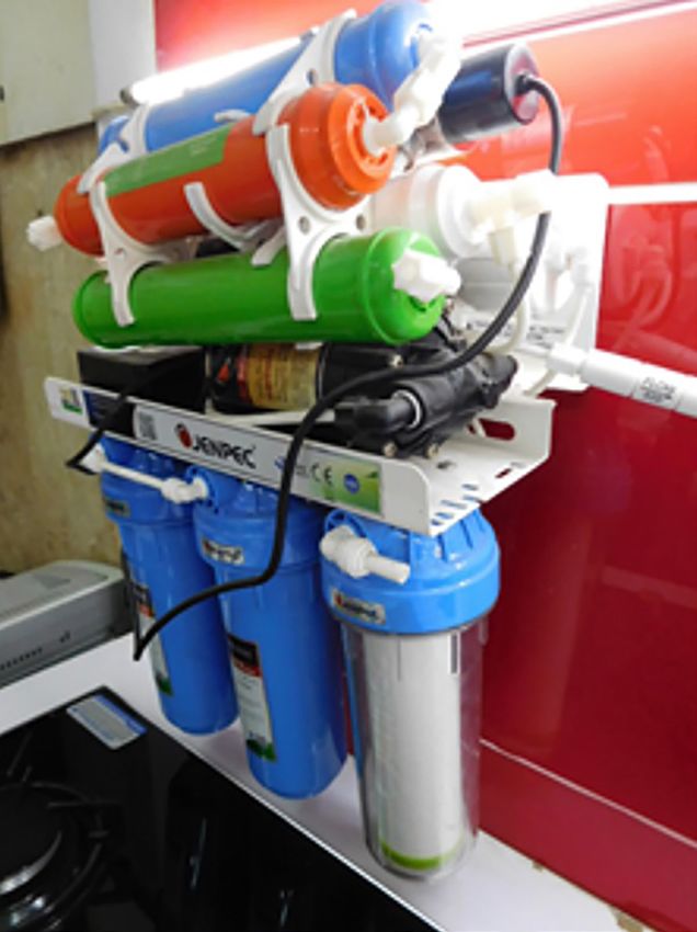
t page 5
doped) in precise materials, which are alternatively missing     ments. Constructing multi-layer substrates from indium
or supplying electrons from their outer shell. As a voltage is   gallium nitride, diamond, boron nitride, aluminum nitride
applied, the free electrons flowing through the circuit “fall”   and aluminum gallium indium nitride, for example, led to
into the microscopic holes – or spaces in the electron ring      LEDs in the UV range emitting at wavelengths as low as
– due to impurities in the doped substrate. By falling into      210 nm.
a lower energy state, they release their excess energy in the
form of light. The wavelength or color released depends on       As with traditional UV sources, LEDs in the UV-C and
the bandgap, or drop in energy, between the materials.           UV-B range are effective at inactivating bacteria and viruses
                                                                 (Bowker et al., 2011; Oguma et al., 2013; Beck et al., 2017;
LEDs were initially developed in the 1950s by German,            Rattanakul and Oguma, 2018) and helminthes eggs as well
British and American researchers working in parallel to          (unpublished). These UV LEDs currently are used in small
advance the electronics, phone, TV and lighting industries.      reactors for batch experiments (Figure 4). LEDs in the UV-A
These early LEDs, which used a gallium phosphide (GaP)           range can degrade harmful organic pollutants like pharma-
substrate solo or doped in nitrogen or zinc oxide, emitted       ceuticals, insecticides and dyes, with the help of photocata-
visible light in the red to green ranges (Grimmeiss and Koel-    lysts like iron, titanium-oxide and persulfate (Matafanova
mans, 1961; Gershenzon and Mikulyak, 1961; Starkiewicz           and Batoev, 2018).
and Allen, 1962). The blue LED, which would complete the
color wheel, proved elusive for three decades. It wasn’t until
the 1980s that a trio of Japanese researchers developed the
high-output blue LED by growing high quality crystals into a
multi-layer gallium-nitride (GaN)-based substrate. This feat
of engineering (Figure 3), and its subsequent impact on the
lighting and electronics industries, earned Isamu Akasaki,
Hiroshi Amano and Shuji Nakamura the Nobel Prize in
Physics in 2014 (Scientific Background on the Nobel Prize        Figure 4. 16W unit with 280 nm UV LEDs used for batch
in Physics 2014).                                                disinfection experiments

Blue LEDs generate white light either by combining with red      From a health and environmental impact standpoint, the
and green LEDs or by illuminating a phosphor coating. The        primary advantage of UV LEDs over other UV lamps is that
breakthrough of the white LEDs transformed the electronics       they are mercury-free. Mercury has toxic effects on human
industry with the advent of computer screens and smart-          health and the environment. As a result, The United Nations
phones. White LEDs also surpassed incandescent light bulbs       Environmental Programme (UNEP), through the Minamata
with higher energy efficiencies and longer lifetime.             Convention on Mercury, is controlling mercury waste and
                                                                 working to eliminate the release of mercury into air, water
UV light-emitting diodes                                         and land by 2020 (Minamata Convention on Mercury).
In the disinfection field, the blue LED paved the way for the
inevitable ultraviolet LED, which was developed through          As semiconductors, LEDs can be turned on and off instanta-
several iterations of manufacturing and material improve-        neously without requiring the 20- to 30-minute warmup time

Figure 3. Illustrations of a light-emitting diode by Johan Jarnestad at The Royal Swedish Academy of Sciences

    6       IUVA News / Vol. 20 No. 1
required by gas vapor lamps. This opens the door for smart          LEDs in the UV-A range have already made their way into
sensor-based UV disinfection technologies that can be powered       everyday life. For instance, getting a manicure or pedicure
on-demand. From a power standpoint, UV LEDs can operate             may involve drying (or “curing”) the shellac nail polish)
from less power than conventional lamps and can be powered          under an array of UV-A and visible LEDs. Other coatings,
by remote or photovoltaic power supplies (Lui et al., 2014). On     adhesives and inks are cured through UV-A LED technology,
the other hand, an equally important fact is that UV LEDs are       like ink used for high-resolution graphic imagery or posters,
considerably less efficient than traditional UV sources. As such,   for example.
they must be powered for a longer time in order to reduce the
spread of harmful pathogens by the same amount as mercury-          These technology trends are just now extending to the UV-B
based lamps.                                                        and UV-C range as well, as Figure 5 shows. For UV-B and
                                                                    UV-C LEDs to be as effective as traditional UV lamps from
From a design standpoint, the primary advantage of UV LEDs          a microbiology perspective, they must reach wall plug effi-
is their compact size, less than 1 mm2. With this incredibly        ciencies of 25 to 39 percent, meaning that 25 to 39 percent
small footprint, multiple diodes can be arranged in unique          of the energy input through the wall plug is output in the
                                   reactor designs as shown         form of light (Beck et al. 2017). Given the current state of
                                   in Figure 5 (Oguma et al.        technology, the wall plug efficiencies of these LEDs is closer
                                   2016). LEDs of different         to 4 percent. However, they are on an upward trend and well
                                   wavelength outputs can           on pace with the development of red, blue and UV-A LEDs
                                   even be combined to              (Figure 6).
                                   optimize inactivation of
                                   specific microorganisms.                                                            page 8 u
                                   Ideally, a tailored UV
                                   LED disinfection system
                                   would target microbial
                                   and chemical contami-
Figure 5. Ring-shaped appa-        nants by combining
ratus for a flow-through reactor   wavelengths from the
composed of two rings with 10      dominant DNA damage
UV LEDs each                       region (260 to 280 nm),
                                   the protein damage region
(below 240 nm) and the UV-A region where external sensi-
tizers (like catalysts or organic matter) are activated and
cause indirect chemical degradation.

Commercially available UV LED reactors on the market
currently range in scale from small hand-held devices to
large-scale municipal treatment units capable of treating
2000 m3/day. The hand-held units include the option to select
LEDs from up to three different wavelengths, including as
low as 254 nm.

Potential applications of UV-C LEDs
Just as computers evolved from the size of a room in 1941 to the
size of a smartphone in 2007, ultraviolet sources and LEDs have
been evolving over the last century. LEDs in the visible range
transformed computer and television monitors and brought
electricity to remote environments, for example, by providing
photovoltaic lighting to an estimated 5% of Africans who
otherwise lacked electricity (“Solar Lighting Products Improve
Energy Access for 28.5 Million People in Africa,” 2014).

                                                                                                  2018 Quarter 1           7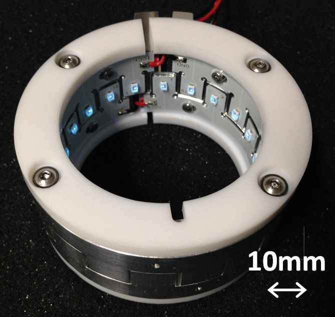
t page 7

Another exciting trend, as reported by Pagan and Lawal                               Beck, S.E.; Ryu, H.; Boczek, L.A.; Cashdollar, J.L.; Jeanis, K.M.; Rosen-
2017 is the number of manufacturers of UV-C LEDs world-                                blum, J.S.; Lawal, O.R.; Linden, K.G. 2017. Evaluating UV-C LED
wide. What started with one company in 2003 has grown to                               disinfection performance and investigating potential dual-wavelength
                                                                                       synergy. Water Res. 109: 207-216.
10 companies based primarily in the United States, Japan,
Taiwan, China and South Korea, each working to improve                               Beck, S.E.; Wright, H.B.; Hargy, T.M.; Larason, T.C.; Linden, K.G. 2015.
their products’ efficiencies and durability.                                           Action spectra for validation of pathogen disinfection in medium-pres-
                                                                                       sure ultraviolet (UV) systems. Water Res. 70: 27-37.
                                                                                     Besaratinia, A.; Yoon, J.I., Schroeder, C., Bradforth, S.E., Cockburn, M.,
                                                                                       Pfeifer, G.P. 2011. Wavelength dependence of ultraviolet radiation-
                                                                                       induced DNA damage as determined by laser irradiation suggests that
                                                                                       cyclobutane pyrimidine dimers are the principal DNA lesions produced
                                                                                       by terrestrial sunlight. Faseb J. 25(9): 3079-3091.
                                                                                     Bolton, J. 2017. Action Spectra: A Review. IUVA News. 19(2): 10-12.
                                                                                     Bolton, J.R. and Cotton, C.A. 2011. The Ultraviolet Disinfection Hand-
                                                                                       book, published by American Water Works Association.
                                                                                     Bowker, C.A.S., Shatalov, M., Ducoste. J. 2011. Microbial UV fluence-
                                                                                       response assesment using a novel UV LED collimated beam system.
                                                                                       Water Res. 45: 2011-2019.
                                                                                     Bukhari, Z; Hargy, T.M.; Bolton, J.R.; Dussert, B.; Clancy, J.L. 1998,
                                                                                       Medium Pressure UV Light for Oocyst Inactivation, J. AWWA, 91: 86-94.
Figure 6. Technology trends of red, blue, UV-A and UV-C                              “Catskill-Delaware Ultraviolet Water Treatment Facility.” Web. 24 Feb
LEDs as measured by wall plug efficiency (Lawal et al. 2017)                           2018
UV-C LEDs are already being incorporated into point-of-use                           Clancy, J.L.; Hargy, T.M.; Marshall, M.M.; Dyksen, J.E. 1998. UV light
units to serve the defense and outdoor industries. They’re                             inactivation of Cryptosporidium oocysts. Journal AWWA. 90(9): 92-102.
being designed into airplanes to disinfect air in the passenger
                                                                                     Downes, A. and Blunt, T.P. 1877. Researches on the effect of light upon
cabin, and they’re being tested for water treatment in small
                                                                                      bacteria and other organisms. Proc. Roy. Soc. 28, 488–500.
towns in the United States.
                                                                                     Duclaux E. In uence de la luminére du soleil sur la vitalité des germes des
                                                                                      microbes. Compt Rendus Hebd des Seances de l’Academie des Sciences
What’s next? This tiny robust light source at the tip of our
                                                                                      1885;100:119-21.
fingers has the potential to transform water disinfection in
developed and low- to middle-income countries alike. In                              Gates, F. L. 1930. A Study of the Bactericidal Action of Ultraviolet Light III.
developed countries, UV-C LEDs can be incorporated into                                The Absorption of Ultraviolet Light by Bacteria. J. Gen Physiol. 14: 31-42.
showerheads to prevent outbreaks of Legionnaires’ disease                            Geisler, T. 1892. Zur Frage uber die Wirkung des Licht auf Bakterien,
in hospitals and hotels. They can be introduced into pipe                              Centralblatt fur Bakteriologie und Parasitenkunde 11, 161– 173.
systems to prevent biofilm formation. In low- to middle-                             Gershenzon, M. and Mikulyak, R.M. 1961. Electroluminescence at p-n
income countries, UV-C LEDs can be designed into hand-                                 Junctions in Gallium Phosphide. J. Appl. Phys. 32(7), 1338-1348.
pumps to disinfect groundwater or studded in bottle caps to                          Grimmeiss, H.G. and Koelmans, H. 1961. Analysis of p-n Luminescence
treat single bottles of water and prevent disease outbreaks.                           in n-Doped GaP. Phys. Rev. 123(6): 1939-1947.
                                                                                     Henri, V.; Helbronner, A.; de Rechlinghausen, M. 1910. Sterilization de
As with every exciting new technological development, the
                                                                                       Grandes Quantites d’Eau par les Rayons Ultraviolets. Compt. Rend.
broad array of applications cannot yet be foreseen; however,                           Acad. Sci., 150:932-934.
it is exciting to watch the transformation unfold. n
                                                                                     Koch R. 1890. Ueber bakteriologische Forschung. Hirschwald (Berlin).
References                                                                           Lawal, O., Pagan, J. Hansen, M. 2017. When Will UV-C LEDs be Suit-
Arnould, E. 1895. Influence de la luminére sur les animaux et sur les microbes,        able for Municipal Treatment? Conference Presentation. IUVA World
  son role en hygiene. in Revue d’hygiène et de police sanitaire, Vol 17, 668-677.     Congress. 18 September 2017.
Beck, S.E.; Hull, N.M.; Poepping, C.; Linden, K.G. 2018. Wavelength-                 Lui, G.Y., Roser, D., Corkish, R., Ashbolt, N., Jagals, P., Stuetz, R. 2014. Photo-
  dependent damage to adenoviral proteins across the germicidal UV                     voltaic powered ultraviolet and visible light emitting diodes for sustainable
  spectrum. Environ. Sci. Tech. 52(1): 223-229.                                        point-of-use disinfection of drinking waters. Sci. Total Environ. 493: 185-196.

      8          IUVA News / Vol. 20 No. 1
Matafonova, G. and Batoev, V. 2018. Recent advances in application of UV Rauth, A., 1965. The physical state of viral nucleic acid and the sensitivity
light-emitting diodes for degrading organic pollutants in water through of viruses to ultraviolet light. Biophys. J. 5, 257-273.
advanced oxidation processes: A review. Water Res. 132: 177-189.
“Scientific Background on the Nobel Prize in Physics 2014.” Nobelprize.org.
“Minamata Convention on Mercury.” United Nations Environment Nobel Media AB 2014. Web. 24 Feb 2018
Oguma, K., Kita, R., Sakai, H., Murakami, M., Takizawa, S., 2013. Appli- “Solar Lighting Products Improve Energy Access for 28.5 Million People
cation of UV light emitting diodes to batch and flow-through water in Africa” Lightingafrica.org. World Bank Group. 2014. Web. 24 Feb
disinfection systems. Desalination 328: 24-30. 2018 https://www.lightingafrica.org/solar-lighting-products-improve-
energy-access-for-28-5-million-people-in-africa
Oguma, K.; Ryo, K.; Takizawa, S. 2016. Effects of Arrangement of UV
Light-Emitting Diodes on the Inactivation Efficiency of Microorganisms Sommer, R., Cabaj, A., Hirschmann, G., Pribil, W., Haidler, T. 2002. UV
in Water. Photochem Photobiol. 92: 314-317. Disinfection of Drinking Water in Europe: Application and Regulation.
In Proc. Of the First Asia Regional Conference on Ultraviolet Tech-
Pagan, J. and Lawal, O. 2017. The Smartphones of Water Disinfection –
nology for Water, Wastewater, and Environmental Applications. Scotts-
How Micro UV-C LED Systems Can Increase Accessibility to Public
dale, Ariz.: International Ultraviolet Association. CDROM.
Health Protection. Conference Presentation. IUVA World Congress. 18
September 2017. Starkiewicz, J. & Allen, J.W. 1962. Injection electroluminescence at p-n
junctions in zinc-doped gallium phosphide. J. Phys. Chem. Solids 23(7):
Paidalwar, A. and Khedikar, I. 2016. Overview of Water Disinfection by
881-884.
UV Technology – A Review, International Journal of Science Tech-
nology & Engineering, 2:09:213-219 USEPA. Long Term 2 Enhanced Surface Water Treatment Rule. 2006. U.S.
Environmental Protection Agency: Washington, DC.
Rattanakul, S.; Oguma, K. 2018. Inactivation kinetics and efficiencies of
UV LEDs against Pseudomonas aeruginosa, Legionella pneumophila Ward, H.M. 1892. Experiments on the action of light on Bacillus anthracis,
and surrogate microorganisms. Water Res. 130: 31-37. Proc. Royal Soc. London 52, 393–400
2018 Quarter 1 9Design Considerations for Creating
an Optimized UV LED System
Brian Jasenak, MS, senior product development engineer
Kopp Glass Inc., www.koppglass.com/UVLED
Contact: solutions@koppglass.com
Introduction: adoption of UV LEDs design engineers take when redesigning mercury vapor
Over the last decade, the ultraviolet (UV) light emitting diode fixtures asks, “What LED will replace the bulb we were
(LED) market has grown substantially. Since 2008, scientists previously using?” However, the question they should ask is,
have been tracking and cataloging commercially available “What light output am I trying to achieve?”
UV LEDs. The data shows a fivefold increase in the number
of companies manufacturing UV LEDs in the past decade. By beginning with the end in mind, engineers can evaluate
Initial growth in UV LED adoption was driven by UV-A all aspects of a UV LED lighting system that determine the
curing applications due to the relative ease of adapting blue ultimate performance of their product. Taking a holistic
LEDs for this near-visible spectral range. However, as UV approach to considering all components of the lighting
LED manufacturers have advanced the technology, we’re system together maximizes the efficiency of the system. In
seeing the development of new applications in deeper UV-B traditional systems, a bulb was a bulb. Following a linear
and UV-C wavelength ranges for game changing disinfection design approach, engineers would select the bulb and design
and sterilization products. around it. Now, LEDs force engineers to simultaneously
consider multiple design components. Those who prevail
With the performance and reliability of UV LEDs consis- in engineering high-performance products understand the
tently improving, LEDs have opened a range of new possibil- interplay between three key UV LED system design consid-
ities for engineers seeking to develop consistently powerful erations: LED selection, optical design and optical material
UV systems where they were once limited by variability selection, and LED array design.
and other inherent design constraints in traditional arc lamp
light sources, such as mercury vapor (Hg). While UV LED LED selection
systems offer numerous benefits such as energy savings, Selecting the right LED for an application can be a daunting
increased design flexibility, enhanced light output and overall challenge. There are nearly 600 UV LEDs available on the
cost savings, designing with UV LEDs brings an entirely new market today; roughly 100 of which transmit in the UV-C
set of challenges for those experienced in traditional tech- region. Once a wavelength is selected, there are many options
nologies of the past. A common mistake is viewing UV LEDs that include different emitting flux, drive currents and beam
as a replacement light source; the approach that many optical angles. There is much to consider in terms of thermal manage-
Figure 1. Range of radiant flux per wavelength for commercially available UV LEDs
10 IUVA News / Vol. 20 No. 1ment, drive current and efficiency, but, regarding optics, the With the performance and reliability of UV
emitting flux and beam angle are the most crucial.
LEDs consistently improving, LEDs have
First, engineers must define the area that needs to be illumi- opened a range of new possibilities for engi-
nated by the UV LED. Working backwards, engineers need neers seeking to develop consistently power-
to determine the amount of flux needed on the target surface.
ful UV systems where they were once limited
Depending on the application, there is often a necessary
level of flux to yield viable results. Once the flux and area by variability and other inherent design con-
are determined, it is time to consider the power per area that straints in traditional arc lamp light sources.
is needed to reach the end goal. For example, in UV curing,
this would be in watt/cm2. The application may require 30 W or optic solution. During this step, it is beneficial to engage
of power on the surface but require 7 W/cm2 peak irradiance. all design groups including the optic manufacturer.
Depending on the specific product application, there will be Often the OEM, lens designer and manufacturer are separate
several performance specifications for the UV light source. parties, which can make it difficult to achieve a fully opti-
Many applications require a targeted peak wavelength for mized design. The lens designer may create an optimized
optimal performance, while some have stringent demands on optic design that would produce an ideal light distribution, but
light output. Examples include phototherapy applications that it is not viable for manufacturing. As a result, the optic could
need to apply targeted UV-A, UV-B or a combination of these be too costly or even impossible to produce without design
wavelengths to a patient’s skin. Another example is laboratory modifications. To produce an optic for both manufacturing
applications that require homogenous UV-C exposure to test and performance, it is important for all parties to work closely
the UV sensitivity of bacteria. Peak wavelength, radiant flux together to reduce development time and prevent costly rede-
and beam angle are just some of the performance specifica- signs. It is helpful to be specific with the light output require-
tions that are specified across the UV LED industry (Figure 1). ments, yet allow for flexibility in the fixture, array and overall
Engineers can find a diode with virtually any peak wavelength product design to optimize the lighting system.
between 240 nm and 400 nm. Key wavelengths, such as 265
nm, 280 nm, 310 nm and 365 nm have options available from When it comes to transparent materials, there is no one-size-
multiple manufacturers. However, the power and efficiency fits-all solution. It is important to understand the interaction
will depend significantly on the LED’s peak wavelength. between the optic material and the UV LED application envi-
ronment. The application temperature, moisture, or chemi-
Optical design and optic material selection cals can influence the optic material transmission and weaken
Now is the time to consider which optic type will be most its resistance to stress. LEDs are all about overcoming the
beneficial to achieve the desired result. An optic will direct variability inherent in traditional sources; engineers who
the emitted rays towards the target surface irradiating the don’t take enough care in material selection will find out the
surface with the appropriate flux or dosage. Often times, hard way that many materials degrade when exposed to the
LEDs are continuously added until a level of peak irradiance UV application environment, thus preventing them from real-
is achieved; however, this is unnecessary if an optic is used. izing the benefits of the technology. A material supplier can
Higher peak irradiance can be achieved with fewer LEDs provide valuable information on material properties. These
while maintaining a certain amount of flux, energy density, specifications can be used to determine if a specific material
or UV dosage on the target surface. is prone to degradation or erosion.
Engineers should evaluate the need for an optic by examining There are many transparent materials out there to be considered
the light output requirements of the system. Depending on the when designing an LED optic. On the surface, they may look
UV dosage, exposure rate, peak irradiance, target distance, similar. However, not all transparent materials will perform
or intensity required an optical engineer can determine what the same. They have unique properties that dictate how they
type of optic is necessary to reach the desired end output. For refract rays. Table 1 summarizes several important properties
example, in water purification, an optical designer can work to consider when evaluating optical materials. It is imperative
closely with the reactor designer to select an optic type that to also keep in mind how the material properties may change
will spread the light effectively to increase the fluence rate. If over time as they are exposed to varied operating conditions.
the reactor designer has determined the light output require-
ments, the optical engineer can likely suggest an array design page 12 u
2018 Quarter 1 11t page 11
For example, a material such as borosilicate glass is highly If LEDs are placed too far apart, the light control that can be
resistant to abrasive conditions, heat cycling and UV radiation achieved with the optic will be limited. As the array widens,
exposure whereas plastics in the same environment will erode the LEDs create multiple point sources. To simplify the
and discolor, resulting in severe transmission loss. issue, imagine each point source emits one ray to the same
exact spot on the optic. The optic can refract each ray toward
UV LEDs, especially in the UV-C region, are still relatively the target surface if the array is under a certain width (this
expensive and are a main cost driver for UV LED systems. Not depends on the optic type). As the array widens, it becomes
only does an optic work to protect LEDs, many times optics increasingly difficult for an optic to refract incident rays that
can reduce the number of UV LEDs required in an array, or the are hitting the optic at different angles (Figure 3).
overall drive current necessary while maintaining or improving
the light output. The result is higher-performing, more reliable
UV LED systems. The following section discusses how the
LED array works to influence the optic design.
LED array design
There are three elements to an array design that should be
considered simultaneously: the spacing of LEDs, the number
of LEDs and their direction. The optic has a significant influ-
ence on these three aspects of LED array design. UV LED Figures 2 and 3. (Left) In a narrow array, LEDs are nar-
spacing is the most critical part of any array design. When rowly spaced, allowing the optic to refract the rays toward
pairing an optic with an array, the width (defined as number the target surface. (Right) In a wide array, LEDs are widely
of LED rows) of the array will dictate the type of optic that space, preventing the optic from refracting the rays toward
can be used. Furthermore, the width will determine the effi- the target surface.
ciency of the optic (Figure 2), as well as the quality of the
light emitted from the array. As a general rule, consider the following descriptions of
linear array sizes when selecting an optic.
Table 1. Important material properties to consider
• single row ( 6 rows of LEDs)
fractive index often changes throughout the UV region.
Absorption is the reduction of light as it travels through LEDs also can be arranged in a limitless number of patterns
Absorption,
Spectral
a material. Conversely, transmission is the amount of (Figure 4). Consider illuminating a square area of 100 mm by 100
light that makes it through. Reflection for transparent
Properties, mm. In some cases, a square array would be suggested since the
materials usually occurs at the surface and is a func-
Transmission
tion of wavelength and index of refraction. This is all area to be illuminated is square. However, if a linear array (single,
and Reflection
highly dependent on type of transparent material used. narrow or medium) was used, then an optic can be designed to
Hardness is the ability of a material to resist being produce the required output. Not only could the optic increase the
Hardness scratched, fractured or permanently deformed by the flux to the target surface, but it also can reduce the overall foot-
sharp edges of another material.
print of the UV LED system resulting in a more compact design.
The resistance to thermal stress can be critical in cer- When designing an array, consider all reasonable array types, the
Thermal
tain applications. Understanding thermal expansion will
Resistance
help ensure that you select a durable material. possible optics that can be used with each array and the overall
Impact resistance measures the ability of a material to
effect this relationship may have on the system.
Impact resist being fractured and to retain surface quality after
Resistance being hit. This value is improved with higher values of
strength, hardness and toughness.
Whether the material is exposed to something as
common as water or other harsh chemicals, it is vital
Chemical to know how the material will perform. Chemical resist-
Resistance ance depends on the composition of the material and
the material supplier can provide information that is
more specific. Figure 4. LEDs provide ample design flexibility.
12 IUVA News / Vol. 20 No. 1It should not be a surprise to learn that the number of LEDs direction. Optics should be considered early in the design
also works side-by-side with LED spacing. As explained process, as they can improve the overall performance of
above, the increased power output that an optic provides can the LED lighting system and in certain cases can be used to
increase the efficiency of the system while allowing for a reduce the number of LEDs required in a lighting system.
decrease in the number of UV LEDs in the array. Optimization When designing a new UV LED lighting system, there are a
of the number of LEDs and their spacing will produce an array few key questions to ask:
that maximizes space and efficiency. The number of LEDs • What is the desired optical performance?
also dictates the level of thermal management that is required. • What array type and optic could produce this perfor-
Some designers tend to build widely spaced LED arrays in mance?
order to create a larger area for heat dissipation. Wide spacing • What array type will provide the greatest flexibility in
can limit the optic types that can be used. In most cases, if the optic selection?
array was more compact other optics become available and • What optics are available?
provide a greater opportunity to improve optical performance • What optical material is best for this application?
while the area for heat dissipation is minimally altered.
Asking these few simple questions will help engineers design
One of the most common mistakes made when creating a UV a better product. The key to realizing the benefits that UV
LED array is adding more LEDs to increase peak irradiance: LEDs offer is to consider all optical components of the
Often a level of power per area must be reached in order for lighting system sooner. Develop the optical components
the UV LED array to perform its intended task. Engineers early in the design process while selecting the UV LED, and
often continue to add UV LEDs to the array to reach their remember that the UV LED spacing, number and direction
desired irradiance level. The added cost associated with each are critical elements to selecting an optic that is right for the
additional LED outpaces the incremental increase in power. module. n
There is a better way – a custom optic can be designed to
increase the power per area on the target surface eliminating
the need to add costlier UV LEDs. Karl Platzer • Oliver Lawal • Fred van Lierop • Michael Santelli •
Henry Kozlowski • Dr. Jim Bolton • Walter Blumenthal
LEDs are directional light sources, meaning they need to be
positioned to allow the light to exit in the desired direction. The new UV Expert Team
The simplest arrays are posi- Consulting in the industry!
tioned on a flat surface with
all LEDs directed in the same
orientation, likely toward
the target surface. However,
some arrays can take advan-
tage of the unique flex- System-Lamp-Ballast-Validation-QC, lamp testing
& Project Management-Marketing
ibility that individual LEDs
provide. For example, the We are a multidisciplinary team of UV experts each
with an average of 20 years of experience. Our main fields
disinfection of bottles, jars, of expertise: traditional UV Lights & future LED solutions.
or canisters can use omnidi-
Figure 5. Omnidirectional array rectional positioning (Figure We now offer our knowledge on a neutral way of proven expert
knowledge to companies seeking consultancy before investing
5) similar to the images seen money and binding internal resources.
below. A ring of UV-C LEDs pointing away from the center
reduces the distance from the UV-C LED to the disinfection
surface increasing irradiance and flux on the surface.
Summary
Optical components are just one part of the LED lighting
system, but they can have a powerful influence on the other
Karl Platzer - Consulting M&A Business Development LLC.
components in the system, including the array design, the www.uvlampconsulting.com
spacing of the LEDs, the number of LEDs needed and their
UV Lamp Consulting_KP_IUVA News_quarter page ad - vers. 1.indd 1 10.12.2017 12:48:32
2018 Quarter 1 13UV LED Technology:
The Times They are A-Changin’
Fariborz Taghipour
Department of Chemical and Biological Engineering, University of British Columbia, Vancouver, Canada
Contact: fariborz.taghipour@ubc.ca
“Come writers and critics of creating novel UV-based technologies and devices that are
Who prophesize with your pen made possible for the first time.
And keep your eyes wide
The chance won’t come again Here is a brief overview of UV LED development, followed
And don’t speak too soon by a discussion on UV LED system development, including
For the wheel’s still in spin UV LED reactors for water treatment, as well as other poten-
And there’s no tellin’ who tial applications.
That it’s namin’
For the loser now UV LED development
Will be later to win A great deal of progress has been made toward the perfor-
For the times they are a-changin’.” mance of UV LEDs in the past several years. Starting in
― Bob Dylan early 2000s with the appearance of the deep UV LED oper-
ating at 280s nm with only a few tens of microwatt power
Introduction (Adivarahan et al., 2002a-b), many innovations in material
UV photonics, photoreaction and photoreactor systems are growth and processing have led in high-efficient UV LEDs,
the key elements of many industries. Recent advances in with powers exceeding over tens or even hundreds of milli-
a new UV source, the ultraviolet light emitting diode (UV watt output. Visible LEDs can operate at over 75% efficiency
LED), create the opportunity for the development of novel for more than 10 years. Currently, the efficiency and life-
UV-based technologies and devices. In fact, UV LEDs could time of UV LEDs are far less evolved than those of visible
potentially transform the UV-based industry by not only LEDs, although recent developments are showing impressive
advancing the design and application of current UV modules, improvement in power output and efficiency.
but also enabling the creation of entirely new products and
markets. Commercial deep UV LEDs have seen a major performance
enhancement in terms of both efficiency and power, as well
LEDs are semiconductor devices that emit radiation of a as cost reduction. It is predicted that UV LED’s recent price
single wavelength. With recent breakthroughs in the devel- reduction will see the UV disinfection/purification market,
opment of new material synthesis and device technologies, which employs UVC, take over the UV curing market, which
LEDs can now be designed to produce UV radiation at a utilizes UV-A, by 2019 to 2020 (UV LED Market, 2016).
range of peak wavelengths. LEDs offer several advantages Although the UV-A LED market is expected to grow substan-
compared to conventional UV sources, such as UV lamps. tially from US$107 million in 2015 to US$357 million by
These include compact and robust design, lower voltages and 2021, the UV-C LED market is predicted to grow even
power requirements, longer lifetime and the ability to turn on more dramatically from US$7 million in 2015 to US$610
and off instantly and with very high frequency. The specific million by 2021, according to the technology market analyst
features of UV LEDs make them an attractive alternative for company Yole Développement (UV LED Market, 2016). The
replacing UV lamps in a number of applications. However, potential could be even greater, when considering UV LEDs’
UV LEDs can offer much more than replacing conventional ability to enable new technologies and devices. It is suggested
UV sources in existing systems. that, while for many high-end applications UV LEDs are
already competitive since they facilitate major advances and
The generation of high-energy UV photons from a solid- contribute only a small fraction to the overall cost, as UV
state miniature form-factor operating at low power makes LED performance improves over time, many more applica-
UV LED a technology enabler. Presenting major advances tion areas will be determined (Kneissl, 2016).
in design, performance and application of the existing
UV-based systems is an important function of UV LEDs, UV LED reactor for water treatment
but, perhaps, much more important is providing the ability UV LEDs can be designed to produce UV radiation at an
14 IUVA News / Vol. 20 No. 1optimal germicidal wavelength. The advantages of UV photo-physical (repeated disturbance of high-intensity pulses
LEDs, compared to traditional low- and medium-pressure on bacterial structure) effects (Krishnamurthy et al., 2007).
UV lamps, make them an appealing substitute for UV lamps Thus, the special features of UV LEDs could be explored and
in water treatment systems, in particular for applications with adjusted for developing better water treatment reactors.
low and intermittent flows. At present, UV-C LEDs cannot
compete with UV lamps in terms of power output, efficiency One of the most significant advantages of UV LEDs is the
and energy cost. However, there are still various possible flexibility they offer in reactor design by providing a higher
applications for UV LED technology within the water sector, degree of freedom in reactor configuration and optimiza-
including UV water treatment systems for drinking water, tion. The performance of UV reactor systems used for any
such as point-of-use (POU) applications. photoreactions or photo-initiated reactions is a function of
the interaction of three phenomena: fluid dynamics, radia-
The POU water purification market is undergoing a major tran- tion distribution and kinetics. All these phenomena can be
sition due to an unprecedented growth in demand, resulting better controlled in a UV LED reactor compared to a UV
from higher awareness and economic growth, particularly in lamp reactor (Taghipour, 2013), as explained in the following
developing countries. This massive growth has not been accom- sections (Fig. 1).
panied by a corresponding development of new technologies
and products, which has created a technology gap. This tech-
nology gap can be addressed by developing UV LED reactors
that eliminate microbial contaminants, operate at low power and
are practically maintenance-free. The conventional UV reactors
operating with UV lamps have several limitations, including
high power/voltage operation, high maintenance and high oper-
ating cost, which may limit their use in non-municipal water
treatment systems. The UV LED reactors may have the poten-
tial to overcome many of the limitations of the existing UV lamp
reactors and other currently used water treatment solutions. Figure 1. Controlling kinetics, radiation distribution and hydro-
dynamics in UV LED reactors: (1) Adjustable wavelength for
For example, when a continuous supply of electricity is promoting targeted photoreaction, (2) Focusable radiation for
available, many technologies for POU water treatment are producing suitable fluence distribution, (3) Controllable hydro-
possible; however, rural communities, especially in devel- dynamics for generating appropriate velocity distribution.
oping countries, often do not have continuous access to elec-
tricity and are at great risk of being exposed to unsafe water Hydrodynamics
supplies. This shortcoming can be addressed by designing The fluid dynamics of UV lamp reactors can be controlled by
UV LED water treatment systems, which can be battery or specifying the reactor geometry or using internal flow modifiers;
solar cell operated and use renewable energy. however, the typical shapes and sizes of UV lamps limit varia-
tions in reactor geometry and positioning of flow restrainers.
UV LEDs possess important features that do not exist in UV Further, UV lamps are typically placed inside of the reactors,
lamps. Some of those features, e.g., wavelength diversity and which causes interference with the reactor fluid flow, often
the ability to generate pulsed irradiation, could potentially without much control over the resulting velocity distribution.
impact the inactivation of microorganisms and reactor effi- However, small UV LEDs can be positioned in different places
ciency (Song et al., 2016). With regard to wavelength diver- and configured to different settings inside and outside of the
sity, UV-C wavelengths (e.g., 250 to 280 nm) cause damage reactor. As a result, the hydrodynamics of UV LED reactors can
to both the DNA and proteins of microorganisms by the be better controlled. For example, LEDs can be placed at the
formation of pyrimidine dimers, while UV-A wavelengths reactor wall, allowing different kinds of static mixers or vortex
(e.g., 360 to 400 nm) are responsible for the oxidative distur- generators to be used in desired locations in the reactor for
bance of bacterial membranes and enzymes by producing generating an appropriate fluid flow and velocity distribution.
active species and photo-modification of tRNAs (Oppezzo,
2001). Therefore, a combination of both wavelengths could Radiation
have a synergistic effect on the inactivation of microorgan- The radiation distribution of UV lamps is mainly of a cylin-
isms. With respect to pulsed irradiation, several mechanisms drical profile that cannot easily be altered. On the other hand,
may contribute to inactivation effectiveness by pulsed irra-
diation; these include photo-chemical, photo-thermal and page 16 u
2018 Quarter 1 15t page 15
the UV LED radiation profile has a principal direction and can Actuators
be emitted at various angular views with adjustable radiation Certain molecules undergo reversible shape changes that can
profiles. As a result, their radiation patterns can be tailored be driven directly by photons, often in the UV range. UV LEDs
for different reactor configurations. For example, different open new avenues for the potential of direct conversion of UV
optical lenses could be applied to create the desirable radia- energy into mechanical energy at the molecular scale. This
tion pattern. In addition, the layout of small-size individual makes possible the development of diverse actuators needed
LEDs can be optimized with greater flexibility than cylin- by the upcoming robotics revolution. One recent study, for
drical UV lamps. While UV lamps often offer one degree of example, demonstrated the fabrication of UV-driven micro-
freedom for controlling radiation distribution, which is the actuators utilizing epitaxial piezoelectric thin films (Kurokawa,
position, UV LEDs offer three degrees of freedom, which are 2015). When the UV LED radiation was irradiated to the surface
the position, direction and pattern. of the thin film, the cantilever deflected proportional to the UV
intensity, due to the coupling of photovoltaic and piezoelectric
Kinetics properties. UV radiation-driven piezoelectric thin-film actuators
The kinetic parameters of photoreaction or photo-initiated could open a new avenue for remote controlled micro-actuators.
reactions are largely fixed for UV lamp reactors. This is
because the low- and medium-pressure UV lamps which are Sensors
used in reactors – for example, in water treatment systems UV LEDs can be applied as the excitation source for fluo-
– have particular emission spectra. UV LEDs, on the other rescence-based biological agent detection or as the activation
hand, can be made to produce UV radiation of a specific source of a photo-activated sensing layer for gas and liquid
peak wavelength with a narrow bandwidth. Their emission detection. This is significant, particularly for gas sensing,
spectra can be tailored to maximize a specific reaction, e.g., because detecting and monitoring hazardous gases and gas
the inactivation of particular microorganisms or the degrada- pollutants in industrial and urban settings is of increasing
tion of certain contaminants through photochemical or photo- importance. Among the variety of sensors currently avail-
catalytic reactions. In addition, UV reactors can be designed able, chemical sensors are one of the most promising types of
to deliver radiation energy with a combination of particular device that can be used for gas detection. However, a draw-
wavelengths to produce a potentially synergistic effect. back of conventional chemical-resistive gas sensors is their
high operating temperature (200°C to 500°C), which results
UV LED systems of new applications in high cost and power consumption, and limits their technical
Emission of UV photons of various wavelengths, intensities applicability in the detection of flammable gases. UV LED
and patterns from a robust and compact source offered by UV irradiation could be an alternative method of activating the
LEDs makes possible several important applications. Here, we semiconductor layer and lead to the development of highly
briefly review a few of these applications; in particular, we look effective photo-activation sensors that operate at ambient
at actuators, sensors and micro-optical devices (Fig. 2). temperatures (Espid & Taghipour, 2016). One recent study
has demonstrated that coupling n-type metal-oxide nano-crys-
talline composites provides excellent sensing performance
toward low concentrations of some model chemicals under
UV LED irradiation (Espid & Taghipour, 2017). UV LEDs
have the potential to greatly contribute to the development of
a new generation of sensors and portable monitoring systems.
Optofluidic devices
Optofluidics is a merging of the fields of optics and microflu-
idics, with many applications, including displays, biosensors,
Figure 2. Application of UV LED in sensors, actuators and lab-on-chip devices, lenses and molecular imaging tools.
micro-optical devices: Sensors: UV LED can activate semi- With the recent advances in UV LED and the generation of
conductor sensing layer for gas and liquid detection; Actua- UV radiation from miniature dimensions, the boundary of
tors: UV LED can generate molecular mechanical energy optics in optofluidic devices can be expanded to high-energy
for actuator development; Optofluidics: UV LED can give UV photons. The UV LED can give rise to the creation of
rise to the creation of next-generation optofluidic devices the next generation of optofluidic devices operating with UV
(Icons designed by Eucalyp from Flaticon). energy with broad capabilities and applications.
16 IUVA News / Vol. 20 No. 1You can also read