Journal of Dredging - Western Dredging Association
←
→
Page content transcription
If your browser does not render page correctly, please read the page content below
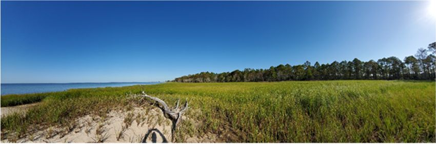
Journal of Dredging
 Volume 19, No. 2, April 2021

 Official Journal of the Western Dredging Association
 (A Non-Profit Professional Organization)

Bucket dredge using a Cable Arm® clamshell in the Lower Passaic River, NJ.

 Produced and printed by the Western Dredging Association (WEDA)

 ISSN 2150-9409
CONTENTS

Journal of Dredging Editorial Board ........................................................................................... ii

Western Dredging Association Board of Directors ..................................................................... ii

Editor’s Note .............................................................................................................................. iii

Dominating Factors in Slurry Transport in Inclined Pipes
by Sape A. Miedema, F. Wang , G. Hong and X. Chen ............................................................ 1

Overcoming Barriers To Beneficial Use Of Dredged Material In The US
by Kristin Searcy Bell, Brandon M. Boyd, Staci L. Goetz, Donald F. Hayes,
Victor S. Magar, Burton Suedel ................................................................................................ 20

Aims and Scope of the Journal .................................................................................................. 43

Notes for Contributors ............................................................................................................... 43

 i
© 2021 Western Dredging Association WEDA Journal of Dredging, Vol. 19, No. 2

 JOURNAL OF DREDGING EDITORIAL BOARD

 Dr. Donald Hayes (Editor), U.S. Army Engineer Research and Development Center, Vicksburg, MS
 Dr. Todd Bridges (Associate Editor), U.S. Army Engineer Research and Development Center, Vicksburg, MS
 Dr. Michael Palermo (Associate Editor), Consultant, Durham, NC
 Dr. Robert Randall (Associate Editor), Texas A&M University, College Station, TX
 Mr. Alan Alcorn, Moffatt & Nichol, San Diego, CA
 Mr. Matt Binsfeld, JF Brennan, La Crosse, WI
 Mr. Steve Garbaciak, Foth Infrastructure & Environment, Glen Ellyn, IL
 Ms. Rebecca Gardner, Anchor QEA, LLC, Seattle, WA
 Mr. William Hanson, Great Lakes Dredge & Dock Company, Chicago, IL
 Dr. Ram Mohan, Anchor QEA, LLC, Horsham, PA
 Mr. Roger Santiago, Environment Canada, Toronto, ON
 Mr. Tim Welp, U.S. Army Engineer Research and Development Center, Vicksburg, MS
 Mr. Steven Wolfe, U.S. Army Corps of Engineers, Concord, MA

 WESTERN DREDGING ASSOCIATION BOARD OF DIRECTORS
 Mr. Alan Alcorn (President/Chair), Moffatt & Nichol, San Diego, CA
 Mr. Matt Binsfeld (Vice President), JF Brennan Company, La Crosse, WI
 Mr. Walter Dinicola (Treasurer), Anchor QEA, LLC, Baltimore, MD
 Ms. Carol Shobrook (Secretary), J.T. Cleary, Inc., Chestnut Ridge, NY
 Dr. Shelly Anghera (Director), Moffatt & Nichol, Carlsbad, CA
 Dr. Todd Bridges (Director), U.S. Army Engineer Research and Development Center, Vicksburg, MS
 Mr. Chuck Broussard (Director), Weeks Marine, Inc., Covington, LA
 Ms. Lori Brownell (Director), Port of Houston, Houston, TX
 Mr. Steve Cappellino (Director), Anchor QEA, LLC, Mission Viejo, CA
 Mr. Jos Clement (Director), CEDA Dredging & Fluid Management, Edmonton, Canada
 Mr. Paul Fuglevand (Director), Dalton, Olmstead & Fuglevand, Inc., Kirkland, WA
 Dr. Donald Hayes (Director), U.S. Army Engineer Research and Development Center, Vicksburg, MS
 Ms. Julie Hile (Director), Hile Group, Normal, IL
 Ms. Janet Kirkton, (Director) Caterpillar, Peoria, IL
 Mr. Robert Ramsdell (Director), Dredging Resources, Downers Grove, IL
 Mr. Steve Shaw, (Director), Sevenson Environmental, Baltimore, MD
 Mr. Dana Trierweiler (Director), Infrastructure Alternatives, Rockford, MI
 Mr. Craig Vogt (Director), Consultant, Hacks Neck, VA
 Mr. Michael Warwick (Director), Manson Construction Co., Jacksonville, FL
 Mr. Marcel Hermans* (Ex-Officio Board Member), Port of Portland, Portland, OR
 Mr. John Vannoy* (Ex-Officio Board Member), Orion Marine, Houston, TX
 Mr. Raul Figueroa* (Ex-Officio Board Member), Panama Canal Authority, Panama
 Mr. Kenneth Mika* (Ex-Officio Board Member), Geosyntec Consultants, Inc., Green Bay, WI
 Mr. Andrew Timmis* (Ex-Officio Board Member), JF Brennan Company, Braintree, MA
 Mr. Ricardo Hernandez Perez* (Ex-Officio Board Member), Grupo MH, Mexico
 Mr. Jan Van Den Driessche* (Ex-Officio Board Member), Jan De Nul, Buenos Aires, Argentina

 * Non-Voting Board Members

 ii
© 2021 Western Dredging Association WEDA Journal of Dredging, Vol. 19, No. 2

 EDITOR’S NOTE
 Now in its 19th year, the Journal of Dredging is gaining traction. This issue marks the Journal’s
 third consecutive quarterly publication containing multiple manuscripts. Sufficient manuscripts
 are under review to publish issues in July and October 2021. But, plenty of space remains in
 upcoming as well as in future issues. Garnering sufficient high-quality submissions to maintain
 a consistent publication schedule remains our most significant challenge. I hope that you will
 consider submitting a manuscript for consideration. As editor, I am committed to a fair and
 thorough review process. If you have information about an interesting project, informative data,
 or any other publication ideas, but need help getting it into a publishable manuscript, please
 reach out to me; I will be glad to help. We need your submissions!

 This issue of Western Dredging Association’s (WEDA) Journal of Dredging contains two
 interesting manuscripts. The first provides a technically sound basis for analyzing slurry
 transport in inclined pipes. The results are very useful for estimating slurry flows from deep
 depths through an inclined pipe. The second paper discusses a range of approaches to increase
 beneficial use, specifically in the United States, significantly compared to the long-term
 historical rate of about 30%. This paper is particularly timely given the U.S. Congress’ call in
 the Water Resources Development Act of 2020 to prioritize beneficial use. I appreciate Mr.
 Craig Vogt shepharding this manuscript through the review process in a manner that helped me
 avoid potential conflicts of interest as a co-author.

 The quality of any journal depends on the effort reviewers invest in providing objective, critical
 feedback to authors. Our reviewers have been outstanding and responsive, allowing us to
 maintain a relatively expedient publication schedule. Further, their reviews have been
 constructive, helping authors improve their manuscripts prior to publication. As an author, I
 really appreciate it when someone invests their time to help me increase the quality of a
 publication. As an editor, I am especially appreciative of our reviewers.

 If you have suggestions for the journal or questions about potential submissions, please contact
 me.

 Don Hayes
 Editor, WEDA Journal of Dredging
 April 2021

 iii

© 2021 Western Dredging Association WEDA Journal of Dredging, Vol. 19, No. 2

 DOMINATING FACTORS IN SLURRY TRANSPORT IN INCLINED PIPES

 Sape A. Miedema1, F. Wang2, G. Hong3, and X. Chen4

 ABSTRACT
In deep sea mining, the valuable materials will often be transported to the surface by means of slurry
transport through pipelines, using centrifugal pumps to generate the pressure. The slurry transport pipeline
has vertical, but also inclined trajectories. It is thus of interest what are the dominating factors in slurry
transport in inclined pipes. Here this is investigated for Newtonian settling slurries. Experiments to
investigate the dominating factors in slurry transport in inclined pipes were carried out in the CCCC
National Engineering Research Center of Dredging Technology and Equipment, Shanghai, China. These
experiments were carried out in a Dp=0.3 m pipe with sand with a d50 of 0.77 mm, concentrations up to
16%, inclination angles up to 44° and line speeds up to 7 m/s.

The physics of slurry transport can be divided into 5 main flow regimes. Each flow regime has its
dominating physics. The stationary bed regime is based on bed friction, the sliding bed flow regime on
sliding friction, the heterogeneous flow regime on collisions and collision intensity, the homogeneous flow
regime on wall friction and the sliding flow regime on sliding friction. So, each flow regime requires its
own approach how to deal with inclined pipes. Models in literature most often multiply the so-called solids
effect with the cosine of the inclination angle, without considering different flow regimes, which is
considered here as incorrect. Because different flow regimes respond differently, also the transitions
between the flow regimes will depend on the inclination angle. It should be noted however that the potential
energy term always dominates the hydraulic gradients measured.

Keywords: Slurry transport, inclined pipes, flow regimes.

 INTRODUCTION
The research question here is, what is the influence of the inclination angle on the hydraulic gradient, on
the Limit of Stationary Deposit Velocity (LSDV) and on the Limit Deposit Velocity (LDV). The effect of
inclined pipes is expressed based on the length of the pipe, not the horizontal distance. The hydraulic
gradient is a dimensionless number, used by most researchers to express pressure losses in pipes. By
dividing the pressure losses by the carrier liquid density and the length of the pipeline, a very convenient
dimensionless number is found.

 with (1)

1
 Associate Professor, Delft University of Technology, Mekelweg 2, 2628 CD, Delft, The Netherlands, T:
 ++31-15-2788359, Email: s.a.miedema@tudelft.nl.
2
 Senior engineer, CCCC National Engineering Research Center of Dredging Technology and Equipment,
 China. Email: wangfeixin@cccc-drc.com.
3
 Senior engineer, CCCC National Engineering Research Center of Dredging Technology and Equipment,
 China. Email: hongguojun@cccc-drc.com.
4
 PhD Candidate, Offshore and Dredging Engineering, Delft University of Technology. Email: x.chen-
 1@tudelft.nl.

 1
© 2021 Western Dredging Association WEDA Journal of Dredging, Vol. 19, No. 2

Another very convenient dimensionless number is the relative solids effect, given by:

 ℎ with R 1 (2)

Before focusing on the DHLLDV Framework, first several models/equations from literature are shown.

The Heterogeneous Flow Regime, Durand and Condolios and Gibert.

The basic equation for the solids effect of Durand and Condolios (1952) and Gibert (1960) for inclined
pipes, is adding the cosine of the inclination angle according to:
 /
 / (3)
 , 1 81

The first term in this equation is the Darcy Weisbach hydraulic gradient for the carrier liquid. The second
term is the potential energy term for both the carrier liquid and the solids. The third term is the solids effect
term. So, the solids effect is multiplied with the cosine of the inclination angle to the power of 3/2. This
means the solids effect is decreasing with an increasing inclination angle, whether the inclination is upwards
or downwards. It should be mentioned that the hydraulic gradient is based on the length of the pipe and not
on the horizontal component of the length.

The Heterogeneous Flow Regime, Worster and Denny.

Worster and Denny (1955) have a slightly different approach. They state that the hydraulic gradient in an
inclined pipe equals the sum of the hydraulic gradients of the horizontal component and the vertical
component. This gives the following equation:
 /
 , 1 81 (4)

The difference with Durand and Condolios (1952) and Gibert (1960) is the power of the cosine. In both
cases, the equations match the hydraulic gradient of a horizontal pipe if the inclination angle equals zero
and a vertical pipe if the inclination angle equals 90 degrees, whether the inclination is upwards (positive
inclination angle) or downwards (negative inclination angle). However, in both cases, the Equivalent Liquid
Model (ELM) component for a vertical pipe is missing.

The Heterogeneous Flow Regime, Wilson et al.

For inclined pipes, Wilson et al. (2006) modified the equation for horizontal pipes, matching the reasoning
of Worster and Denny (1955), but with the use of the power M according to:

 , 1 (5)

The power M has a value of 1.7 for uniform or narrow graded sands and decreases to 0.25 for very broad
graded sands. For narrow graded sands the influence of the inclination angle is similar to the Durand and
Condolios (1952) and Gibert (1960) approach with a power of 1.5 versus 1.7 for Wilson et al. (2006). For
medium graded sands with a power around 1, the influence is like the Worster and Denny (1955) approach.

 2
© 2021 Western Dredging Association WEDA Journal of Dredging, Vol. 19, No. 2

The Sliding Bed Regime, Doron et al.

Doron et al. (1997) investigated the influence of inclined pipes, based on their 2LM and 3LM models
(LM=Layer Model). Basically, they multiplied the sliding friction with the cosine of the inclination angle,
and they added the potential energy term, which is proportional with the sine of the inclination angle. They
carried out experiments with inclination angles from -7 to +7 degrees. The resulting data however is
dominated by the potential energy term, because of the small inclination angles.

 DISCUSSION OF LITERATURE
After adding the potential energy terms to the hydraulic gradient in a correct way, the pipe inclination effect
can be considered, by multiplying the solids effect term with the cosine of the inclination angle to a power
ranging from 1.0 to 1.7. Different researchers give different powers, most probably because the models are
either empirical or have different physical backgrounds. This implies that the solids effect reduces to zero
for a vertical pipe, which is doubtful, especially for very small particles giving homogeneous flow (ELM).
One would expect an equation of the following form:

 , 1 1 ℎ (6)

The first term on the right-hand side is the Darcy Weisbach friction, including the mobilized ELM (the
homogeneous solids effect) corrected for the inclination angle. The second term is the potential energy
term. The third term is the solids effect (Erhg) corrected for the inclination angle. So, where the solids effect
decreases with the inclination angle, the homogeneous solids effect increases. In this form a vertical pipe
shows mobilized/reduced ELM behavior, which is observed by Newitt et al. (1961). Other flow regimes
were not considered. Although this equation is a big improvement compared to the equations from
literature, it does not yet distinguish explicitly between the flow regimes.

 DHLLDV FRAMEWORK MODELING
The DHLLDV Framework combines the 5 flow regimes into one hydraulic gradient or relative solids effect
curve. Figure 1 shows the definitions used in a cross section of the pipe used for the stationary and sliding
bed flow regimes. A short summary of each flow regime is given, since Miedema (2017) already explained
the detailed derivation for each flow regime.

Pure Carrier Liquid in an Inclined Pipe

The hydraulic gradient for pure carrier liquid in an inclined pipe can now be determined with:

 , (7)

So apparently, the hydraulic gradient increases with the sine of the inclination angle (Figure 2). This also
means that a downwards slope with a negative inclination angle gives a negative sine and thus a reduction
of the hydraulic gradient. In this case the hydraulic gradient may even become negative.

Stationary Bed Regime in an Inclined Pipe

Since the bed is not moving, the friction between the bed and the pipe wall compensates for the weight
component of the bed. The hydraulic gradient can now be determined with:

 , (8)

 3

© 2021 Western Dredging Association WEDA Journal of Dredging, Vol. 19, No. 2 Dp Qm τ1 τ1 L Lꞏsin(θ) θ .A p Figure 2. Pure carrier liquid in an inclined pipe. Figure 1. Definitions. which is the hydraulic gradient of a stationary bed in a horizontal pipe plus the sine of the inclination angle. The weight of the solids does not give a contribution to the hydraulic gradient, since the solids are not moving. See Figure 3: The stationary bed regime in an inclined pipe. Sliding Bed Regime in an Inclined Pipe The hydraulic gradient for the sliding bed regime is: , 1 (9) The relative excess hydraulic gradient or relative solids effect, Erhg,θ, is now: , , ℎ , (10) See Figures 4 and Figure 5: A sliding bed in an inclined pipe. The friction velocity u* is defined as √(λ/8)ꞏvls, a measure for the friction on the pipe wall and also a measure for the thickness of the viscous (laminar) sub layer. Heterogeneous Regime in an Inclined Pipe In an inclined pipe the effective terminal settling velocity perpendicular to the pipe wall gives a potential energy term of (β is part of the hindered settling model): ℎ ℎ (11) , For the kinetic energy losses, the angle of attack has to be adjusted in an inclined pipe. The angle of attack is defined as the ratio between the terminal settling velocity and the velocity at the thickness of the viscous sub layer, giving (see Figure 6): 4

© 2021 Western Dredging Association WEDA Journal of Dredging, Vol. 19, No. 2 Wb,sꞏsin(θ) Dp Wb,sꞏcos(θ) Qm τ1 τ 12 L Lꞏsin(θ) . A1 µsfꞏWb,sꞏcos(θ) p θ Wb,s Figure 3: The stationary bed regime in an Figure 4: The submerged weight components inclined pipe. and the sliding bed friction force. Dp Dp Qm Qm ꞏu * ) 6 of s(θ 11. g le τ1 ꞏco τ1 An ack at t s ꞏW b , τ 12 µ sf τ 12 (θ) τ2 cos (θ) v ꞏt θ) Lꞏsin(θ) si n v Lꞏsin(θ) . A1 ꞏs in( L v ꞏt t p θ θ W b,s .A p .A2 p Figure 5: A sliding bed in an inclined pipe. Figure 6: Heterogeneous flow in an inclined pipe, the angle of attack. / / , (12) . ∗ So, for very small particles with vt

© 2021 Western Dredging Association WEDA Journal of Dredging, Vol. 19, No. 2

 ℎ ,

Sliding Flow Regime or Fully Stratified Flow in an Inclined Pipe

The sliding flow regime behaves the same as the sliding bed regime, since both regimes are dominated by
sliding friction, so:

 , 1 (15)

The relative excess hydraulic gradient or relative solids effect Erhg,θ is now:

 , ,
 ℎ , (16)

The Limit Deposit Velocity

The Limit of Stationary Deposit Velocity is affected by the pipe inclination. In an ascending pipe, the cross-
sectional averaged line speed has to be higher compared to a horizontal pipe in order to make a bed start
sliding. In a descending pipe this line speed is lower. It is even possible that in a descending pipe the bed
will always slide because of gravity. The Limit of Stationary Deposit Velocity is at the transition of the
stationary bed regime and the sliding bed regime. The Limit Deposit Velocity, defined as the line speed
above which there is no stationary or sliding bed, is determined by either the potential energy losses or a
limiting sliding bed. In both cases this is affected by the cosine of the inclination angle, the component of
gravity perpendicular to the pipe wall. Since in both cases the Limit Deposit Velocity depends on the cube
root of this cosine, the Limit Deposit Velocity will decrease according to Miedema (June 2016):
 /
 , , , (17)

Because of the cube root of this cosine, this means that for angles up to 45º the reduction is less than 10%.

 DISCUSSION OF MODELING
For the stationary bed regime, only the potential energy term of the pure liquid must be added to the
hydraulic gradient of the mixture (basically the pure liquid hydraulic gradient in the restricted area above
the bed). For all other flow regimes, the potential energy term of the mixture must be added, together with
a correction of the so-called solids effect. The result of this is a higher line speed for the intersection point
of the stationary bed curve and the sliding bed curve. So, in general an increase of the Limit of Stationary
Deposit Velocity (LSDV) with increasing inclination angle. This may however also result in omission of
the occurrence of a sliding bed for an inclined pipe, where a sliding bed would occur in a horizontal pipe.
This makes sense, since a higher line speed is required to make a bed start sliding, there is the possibility
that the bed is already fully suspended before it could start sliding. With negative inclination angles, a
stationary bed may never occur if the arctan of the sliding friction coefficient of the sand with the pipe wall
is smaller than the inclination angle. Usually this sliding friction angle or angle of external friction will be
about 20°. So, if the descending inclination angle is smaller than -20°, the LSDV does not exist and even
at zero-line speed the bed is already sliding. This is also the reason why the Wilson et al. (2006) graph for
the correction for inclined pipes starts at -20°.

In the sliding bed/sliding flow regime and the heterogeneous regime, the hydraulic gradient is lower for an
inclined pipe compared with a horizontal pipe, if the potential energy term of the mixture (static head) is
not considered, especially for small particles in the heterogeneous regime. For the heterogeneous regime,

 6
© 2021 Western Dredging Association WEDA Journal of Dredging, Vol. 19, No. 2

there is a difference between ascending and descending pipes, due to the term with the angle of attack in
the kinetic energy losses. The decrease in an ascending pipe is smaller than in a descending pipe and could
even give a small increase in an ascending pipe at low line speeds. The transition line speed of the
heterogeneous flow regime to the homogeneous flow regime will also decrease with increasing inclination
angle.

In case of a sliding bed one may expect more stratification in an ascending pipe compared to a descending
pipe, due to the higher line speed in an ascending pipe to make the bed start sliding. In other words, a higher
shear stress on the bed is required in an ascending pipe, resulting in a thicker sheet flow layer at the top of
the bed.

The hydraulic gradients of the inclined pipes are determined per meter of inclined pipe and not per meter
of horizontal pipe. In order to find the correct hydraulic gradient curves for an inclined pipe, one first has
to determine the hydraulic gradient curves for each flow regime individually. The resulting curve can be
found by comparing flow regime curves with the line speed as a variable.

1. If the sliding bed hydraulic gradient (SB) is smaller than the stationary (fixed) bed hydraulic gradient
 (FB), the sliding bed hydraulic gradient (SB) is chosen, otherwise the stationary (fixed) bed hydraulic
 gradient (FB). The resulting curve is named the FB-SB curve, or in a descending pipe with an angle
 smaller than about -20°, the SB curve.
2. In the case of sliding flow (SF, large particles), d>0.015ꞏDp according to Wilson et al. (2006), this is
 also the final curve (see Miedema (2018a) and (2018b) for a more detailed criterion). This curve is
 named the FB-SB-SF curve, or in a descending pipe with an angle smaller than about -20°, the SB-SF
 curve. If there is no sliding flow (small and medium sized particles) steps 3 and 4 must be taken.
3. If the heterogeneous flow regime hydraulic gradient (He) is smaller than the FB-SB hydraulic gradient,
 the heterogeneous hydraulic gradient (He) is chosen, otherwise the FB-SB hydraulic gradient. The
 resulting curve is named the FB-SB-He curve, or in a descending pipe with an angle smaller than -20°,
 the SB-He curve. Depending on the parameters (particle and pipe diameter), it is possible that this curve
 does not contain a sliding bed regime. In that case the resulting curve is the FB-He curve. The particles
 will be so small that sliding flow will not occur in this case.
4. If there is no sliding flow and the homogeneous flow regime hydraulic gradient (Ho) is larger than the
 FB-SB-He hydraulic gradient, the homogeneous hydraulic gradient (Ho) is chosen, otherwise the FB-
 SB-He or FB-He hydraulic gradient. The resulting curve is named the FB-SB-He-Ho curve, or in a
 descending pipe with an angle smaller than -20°, the SB-He-Ho curve.

It may be clear that the resulting hydraulic gradient curves do not respond in a single way to the inclinations
angle, since each flow regime has its own characteristic behavior. This implies that the models from
literature are not useable, since the Durand and Condolios (1952) , Worster and Denny (1955) and Wilson
et al. (2006) models are created only for the heterogeneous flow regime and constant transport
concentration, while the Doron and Barnea (1997) model was created for a sliding bed and constant spatial
concentration. The reality seems to be more complicated.

 VALIDATION
De Vreede (2018), carried out experiments at the National Engineering Research Center for Dredging
(NERCD) in Shanghai. The experiments were carried out with a flow loop with a pipe diameter of 300 mm.
It contains a measurement section of over 110 meters, part of which is inclinable. Pipe inclination angles
of 17.9, 28.9 and 44 degrees were tested with slurry concentrations up to 15 % at flow velocities between
2 and 7 m/s. The sand used in the experiments had a d50 of 0.77 mm on average. The flow velocities (line
speeds), delivered concentrations, total pressures, differential pressures and pump data were recorded.

 7
© 2021 Western Dredging Association WEDA Journal of Dredging, Vol. 19, No. 2

Conducting these experiments on this scale under controlled laboratory conditions is a unique research.
Figure 7 gives a schematic display of the test setup.

In Figure 7 the slurry would "start" at the slurry tanks (1) (not displayed). Upstream from the slurry tanks,
the water reservoir is located. The slurry tanks and water reservoir are connected via a set of pipes and
valves. The pump is located at 2, downstream from the reservoirs in the figure. Directly after the pump a
section that serves as a U-loop (3) is found. The U-loop is outfitted with 2 differential pressure meters (one
on each leg) and an ultrasonic density meter. After the U-loop, the pipe is led through a water basin (4) that
can serve as cooling section. From the cooling system, the pipe is led upwards where the electromagnetic
flow meter (5) is attached to the vertical ascending leg of the vehicle crossing. Directly downstream from
the vehicle crossing, the inclinable segment (6) starts with the ascending section, then a 180 degree turn
and the descending section. Several differential pressure meters and total pressure sensors are attached to
it. The horizontal section (7) begins right after the inclinable segment downstream from the descending
section. This horizontal section includes differential pressure meters and total pressure sensors. The
horizontal pipe has a Perspex observation section built in to monitor sliding or stationary beds. After the
horizontal measurement section, the second 180 degree turn (8) is located which leads the flow led back to
the slurry tanks. The ascending and descending legs of the inclinable section have a combined maximum
length of approximately 50 meters depending on the inclination angle. At inclination angles over 18
degrees, the inclinable section is shortened to fit under the roof of the laboratory. The horizontal
measurement section excluding the inclinable section is a little under 60 meters long. Except for the
connections at the slurry reservoir, the pipe diameter of the whole setup is 300 mm. Figure 8 shows the
inclinable sections with inclination angles of 20, 30 and 45 degrees, both ascending and descending.
Because the top of the inclinable section did not completely fit in the building, the angles used were slightly
smaller, 17.9, 28.9 and 44 degrees. The lengths of the inclinable sections are 11.5 m, 17.5 m and 26.5 m. A
detailed description of the experimental setup including the transducers and measurement methods used
can be found in de Vreede (2018). The facility is shown in Figure 9.

 Figure 7: Schematic display of the test setup (source: de Vreede (2018)).

 8
© 2021 Western Dredging Association WEDA Journal of Dredging, Vol. 19, No. 2

Figure 8: The inclinable section with inclination angles of 20, 30 and 45 degrees (source: de Vreede
 (2018)).

The experiments were carried out with intended constant delivered concentrations of 0%, 2.5%, 5%, 7.5%,
10% and 12.5%. In reality, it was difficult to obtain constant delivered concentrations during the
experiments. Based on the way the experiments were carried out, an almost constant amount of solids in
the whole system, the assumption of an almost constant spatial volumetric concentration is more realistic.
This spatial concentration is also required in the DHLLDV model described here. Still there are differences
in the concentration between the experiments at different inclination angles. Since the inclinable section
contains both the ascending and the descending pipe and the hydraulic gradients were measured
simultaneously, there may have been a difference in the spatial concentrations between the ascending and
descending pipes. It is likely that the ascending pipe had a slightly higher spatial concentration compared
with the descending pipe, especially at low line speeds.

 Figure 9: The testing facility with the inclined loop.
The experimental data has been corrected for these effects, based on the potential energy component of the
hydraulic gradient, since this component does not depend on the modelling of the solids effect. The resulting

 9
© 2021 Western Dredging Association WEDA Journal of Dredging, Vol. 19, No. 2

hydraulic gradients are shown in Figure 10, Figure 11, Figure 12, Figure 13, Figure 14 and Figure 15. The
actual spatial volumetric concentrations used in the graphs are 0%, 2%, 5%, 7.5%, 10% and 13.5%.

Figure 10 shows the hydraulic gradient curves and experimental data for pure liquid. The pipe wall
roughness is calibrated based on these experiments, resulting in a good match. So, the theoretical
assumption of the potential energy term for all inclined pipes seems to be valid. It should be mentioned
here that it is always advised to check experimental data of something known, since there may be errors in
the measurement.

The data points in the ascending pipe show a very good correlation with the theoretical curves, while the
data points in the descending pipes show more scatter. Figure 11, Figure 12, Figure 13, Figure 14 and
Figure 15 show the hydraulic gradient curves and experimental data for the mixtures. Based on the theory
and the way the experiments were carried out, one may expect the following phenomena:
 1. In the ascending pipes there will be a fixed bed regime at low line speeds, followed by the
 heterogeneous regime and the homogeneous regime (FB-He-Ho). The sliding bed regime will not
 occur due to the combination of particle and pipe diameters and the spatial concentrations. So, there
 is expected to be a direct transition from the fixed bed regime to the heterogeneous regime.
 2. In the descending pipes there may be some fixed bed regime at very low line speeds at an inclination
 angle of -17.9°, followed by the sliding bed regime, the heterogeneous regime and the
 homogeneous regime. The inclination angle of -17.9° is already close to the expected friction angle
 of 20°. For the inclination angles of -28.9° and -44°, the sliding bed will already occur at zero line
 speed (compare with a brick on an inclined slope, the brick will start sliding if the inclination angle
 is larger than the friction angle). This sliding bed regime is followed by the heterogeneous regime
 and the homogeneous regime (SB-He-Ho).
 3. Because of the layout of the circuit one may expect some accumulation of solids in the horizontal
 pipe sections at very low line speeds, resulting in a decrease of the spatial concentration in the
 inclinable sections. This will result in slightly lower hydraulic gradients at these low line speeds in
 the ascending pipe and slightly higher hydraulic gradients in the descending pipes, especially at the
 higher spatial concentrations.
 4. Because of possible deceleration and accumulation in the ascending pipe and acceleration in the
 descending pipe, the spatial concentration in the ascending pipe may be slightly higher than in the
 descending pipe, resulting in some underestimation of the hydraulic gradient in the ascending pipe
 and in absolute value overestimation in the descending pipe, based on the overall average spatial
 concentration.

 CONCLUSIONS AND DISCUSSION
 Models from literature multiply the so-called solids effect with the cosine of the inclination angle to a
 power between 0.25 and 1.7, based on the heterogeneous flow regime only or the sliding bed regime
 only. These models do not take the homogeneous (reduced) Equivalent Liquid Model (ELM) into
 consideration for very high inclination angles. The consequence is, that there is no solids effect in
 vertical pipes, which is doubtful.

 The use of the cosine of the inclination angle on the solids effect for the sliding bed regime seems
 appropriate, a good first estimate. However, for the heterogeneous flow regime this is more
 complicated, resulting in a difference for an ascending compared to a descending pipe. In this case an
 ELM component containing the sine of the inclination angle should be added.

 10
© 2021 Western Dredging Association WEDA Journal of Dredging, Vol. 19, No. 2

 Carrier Liquid Based Hydraulic Gradients Without Fines, Cvs
 1.00

 0.90
 θ=44.00 º
 0.80

 θ=28.90 º
 0.70

 0.60 θ=17.90 º

 0.50
 θ=0.00 º
 0.40
 Carrier Liquid Based Hydraulic Gradient (m/m)

 θ=-17.90 º
 0.30

 0.20 θ=-28.90 º

 0.10
 θ=-44.00 º
 0.00

 Limit Deposit
 -0.10
 Velocities

 -0.20 Exp. θ=+44.0 º

 -0.30
 Exp. θ=+28.9 º
 -0.40

 Exp. θ=+17.9 º
 -0.50

 -0.60 Exp. θ=+00.0 º

 -0.70
 Exp. θ=-17.9 º
 -0.80

 Exp. θ=-28.9 º
 -0.90

 -1.00 Exp. θ=-44.0 º
 2.0 2.5 3.0 3.5 4.0 4.5 5.0 5.5 6.0 6.5 7.0
 Line Speed (m/s)
 Dp=0.3000 m, d50=0.770 mm, Rsd=1.598, μsf=0.416, ρcl =1.020 ton/m3, Cvb=0.55, Cvs =0.000, Fines=0.00%

 Figure 10. Inclined pipes Cvs=0.0%, experiments versus DHLLDV.

 11
© 2021 Western Dredging Association WEDA Journal of Dredging, Vol. 19, No. 2

 Carrier Liquid Based Hydraulic Gradients Without Fines, Cvs
 1.00

 0.90
 θ=44.00 º
 0.80

 θ=28.90 º
 0.70

 0.60 θ=17.90 º

 0.50
 θ=0.00 º
 0.40
 Carrier Liquid Based Hydraulic Gradient (m/m)

 θ=-17.90 º
 0.30

 0.20 θ=-28.90 º

 0.10
 θ=-44.00 º
 0.00

 Limit Deposit
 -0.10
 Velocities

 -0.20 Exp. θ=+44.0 º

 -0.30
 Exp. θ=+28.9 º
 -0.40

 Exp. θ=+17.9 º
 -0.50

 -0.60 Exp. θ=+00.0 º

 -0.70
 Exp. θ=-17.9 º
 -0.80

 Exp. θ=-28.9 º
 -0.90

 -1.00 Exp. θ=-44.0 º
 2.0 2.5 3.0 3.5 4.0 4.5 5.0 5.5 6.0 6.5 7.0
 Line Speed (m/s)
 Dp=0.3000 m, d50=0.770 mm, Rsd=1.598, μsf=0.416, ρcl =1.020 ton/m3, Cvb=0.55, Cvs =0.020, Fines=0.00%

 Figure 11. Inclined pipes Cvs=2.0%, experiments versus DHLLDV.

 12
© 2021 Western Dredging Association WEDA Journal of Dredging, Vol. 19, No. 2

 Carrier Liquid Based Hydraulic Gradients Without Fines, Cvs
 1.00

 0.90
 θ=44.00 º
 0.80

 θ=28.90 º
 0.70

 0.60 θ=17.90 º

 0.50
 θ=0.00 º
 0.40
 Carrier Liquid Based Hydraulic Gradient (m/m)

 θ=-17.90 º
 0.30

 0.20 θ=-28.90 º

 0.10
 θ=-44.00 º
 0.00

 Limit Deposit
 -0.10
 Velocities

 -0.20 Exp. θ=+44.0 º

 -0.30
 Exp. θ=+28.9 º
 -0.40

 Exp. θ=+17.9 º
 -0.50

 -0.60 Exp. θ=+00.0 º

 -0.70
 Exp. θ=-17.9 º
 -0.80

 Exp. θ=-28.9 º
 -0.90

 -1.00 Exp. θ=-44.0 º
 2.0 2.5 3.0 3.5 4.0 4.5 5.0 5.5 6.0 6.5 7.0
 Line Speed (m/s)
 Dp=0.3000 m, d50=0.770 mm, Rsd=1.598, μsf=0.416, ρcl =1.020 ton/m3, Cvb=0.55, Cvs =0.050, Fines=0.00%

 Figure 12. Inclined pipes Cvs=5.0%, experiments versus DHLLDV.

 13
© 2021 Western Dredging Association WEDA Journal of Dredging, Vol. 19, No. 2

 Carrier Liquid Based Hydraulic Gradients Without Fines, Cvs
 1.00

 0.90
 θ=44.00 º
 0.80

 θ=28.90 º
 0.70

 0.60 θ=17.90 º

 0.50
 θ=0.00 º
 0.40
 Carrier Liquid Based Hydraulic Gradient (m/m)

 θ=-17.90 º
 0.30

 0.20 θ=-28.90 º

 0.10
 θ=-44.00 º
 0.00

 Limit Deposit
 -0.10
 Velocities

 -0.20 Exp. θ=+44.0 º

 -0.30
 Exp. θ=+28.9 º
 -0.40

 Exp. θ=+17.9 º
 -0.50

 -0.60 Exp. θ=+00.0 º

 -0.70
 Exp. θ=-17.9 º
 -0.80

 Exp. θ=-28.9 º
 -0.90

 -1.00 Exp. θ=-44.0 º
 2.0 2.5 3.0 3.5 4.0 4.5 5.0 5.5 6.0 6.5 7.0
 Line Speed (m/s)
 Dp=0.3000 m, d50=0.770 mm, Rsd=1.598, μsf=0.416, ρcl =1.020 ton/m3, Cvb=0.55, Cvs =0.075, Fines=0.00%

 Figure 13. Inclined pipes Cvs=7.5%, experiments versus DHLLDV.

 14
© 2021 Western Dredging Association WEDA Journal of Dredging, Vol. 19, No. 2

 Carrier Liquid Based Hydraulic Gradients Without Fines, Cvs
 1.00

 0.90
 θ=44.00 º
 0.80

 θ=28.90 º
 0.70

 0.60 θ=17.90 º

 0.50
 θ=0.00 º
 0.40
 Carrier Liquid Based Hydraulic Gradient (m/m)

 θ=-17.90 º
 0.30

 0.20 θ=-28.90 º

 0.10
 θ=-44.00 º
 0.00

 Limit Deposit
 -0.10
 Velocities

 -0.20 Exp. θ=+44.0 º

 -0.30
 Exp. θ=+28.9 º
 -0.40

 Exp. θ=+17.9 º
 -0.50

 -0.60 Exp. θ=+00.0 º

 -0.70
 Exp. θ=-17.9 º
 -0.80

 Exp. θ=-28.9 º
 -0.90

 -1.00 Exp. θ=-44.0 º
 2.0 2.5 3.0 3.5 4.0 4.5 5.0 5.5 6.0 6.5 7.0
 Line Speed (m/s)
 Dp=0.3000 m, d50=0.770 mm, Rsd=1.598, μsf=0.416, ρcl =1.020 ton/m3, Cvb=0.55, Cvs =0.100, Fines=0.00%

 Figure 14. Inclined pipes Cvs=10.0%, experiments versus DHLLDV.

 15
© 2021 Western Dredging Association WEDA Journal of Dredging, Vol. 19, No. 2

 Carrier Liquid Based Hydraulic Gradients Without Fines, Cvs
 1.00

 0.90
 θ=44.00 º
 0.80

 θ=28.90 º
 0.70

 0.60 θ=17.90 º

 0.50
 θ=0.00 º
 0.40
 Carrier Liquid Based Hydraulic Gradient (m/m)

 θ=-17.90 º
 0.30

 0.20 θ=-28.90 º

 0.10
 θ=-44.00 º
 0.00

 Limit Deposit
 -0.10
 Velocities

 -0.20 Exp. θ=+44.0 º

 -0.30
 Exp. θ=+28.9 º
 -0.40

 Exp. θ=+17.9 º
 -0.50

 -0.60 Exp. θ=+00.0 º

 -0.70
 Exp. θ=-17.9 º
 -0.80

 Exp. θ=-28.9 º
 -0.90

 -1.00 Exp. θ=-44.0 º
 2.0 2.5 3.0 3.5 4.0 4.5 5.0 5.5 6.0 6.5 7.0
 Line Speed (m/s)
 Dp=0.3000 m, d50=0.770 mm, Rsd=1.598, μsf=0.416, ρcl =1.020 ton/m3, Cvb=0.55, Cvs =0.135, Fines=0.00%

 Figure 15. Inclined pipes Cvs=13.5%, experiments versus DHLLDV.

 16
© 2021 Western Dredging Association WEDA Journal of Dredging, Vol. 19, No. 2

A proper model for inclined pipes should consider the different flow regimes individually and then combine
the flow regime hydraulic gradients, based on which flow regime will occur at which line speed. The effect
of the inclination angle may be different for the different flow regimes. Also, the transition line speeds
between the different flow regimes depend on the inclination angle.

Since the occurrence of the different flow regimes depends strongly on the particle and pipe diameters and
the line speed, this also has a dominant effect on the occurrence of the flow regimes in inclined pipes.
In an ascending pipe a bed will start sliding at a higher line speed and transit to heterogeneous flow at a
lower line speed, with the possibility that there is no sliding bed at all, while there would be in a horizontal
pipe. So, the line speed range of the sliding bed is reduced, possibly to zero. In a descending pipe the
opposite will occur, with the possibility that there is a sliding bed from line speed zero up to the transition
to heterogeneous transport.

The validation with the de Vreede (2018) experiments (CCCC National Engineering Research Center of
Dredging Technology and Equipment, Shanghai, China) show a good correlation. However, it should be
stated that the potential energy terms are dominating, and it is very difficult to identify the exact behavior
of the solids effect. A good correlation means that the theoretical offset of the hydraulic gradient because
of the potential energy matches the experiments, but also the shape of the theoretical hydraulic gradient
curve matches the experiments, with sometimes some explainable deviation at low line speeds.
Now one could say, deduct the potential energy term and then compare the solids effect with the theory.
This is possible; however, this would increase the scatter of the experimental data enormously in
percentage. Also, because a small error in the spatial concentration would be magnified in the solids effect.
Because the data have been taken largely in the heterogeneous regime, above 3.5 m/s, it is difficult to see
if predictions of the LSDV/LDV are correct.

The approach chosen in the DHLLDV Framework as described here, determining hydraulic gradient curves
for each flow regime and then combine/construct the resulting hydraulic gradient curve, seems to work very
well.

 REFERENCES
Doron, P., Simkhis, M., and Barnea, D. (1997). Flow of solid liquid mixtures in inclined pipes. International
 Journal of Multiphase Flow, Vol. 23, No. 2., 313-323.
Durand, R., and Condolios, E. (1952). Etude experimentale du refoulement des materieaux en conduites en
 particulier des produits de dragage et des schlamms. Deuxiemes Journees de l'Hydraulique., 27-55.
Gibert, R. (1960). Transport hydraulique et refoulement des mixtures en conduites. Annales des Ponts et
 Chausees., 130(3), 307-74, 130(4), 437-94.
Miedema, S. A. (2016). Slurry Transport: Fundamentals, A Historical Overview and The Delft Head Loss
 and Limit Deposit Velocity Framework. (1st Edition ed.). (R. C. Ramsdell, Ed.) Miami, Florida,
 USA: Delft University of Technology.
Miedema, S. A. (2017). Slurry transport in inclined pipes. Dredging Summit and Expo (p. 15). Vancouver,
 Canada: WEDA.
Miedema, S. A. (2018a). Slurry transport, fully stratified flow in the sliding flow regime. Dredging Summit
 and Expo (p. 15). Norfolk, Virginia, USA.: WEDA.
Miedema, S. A. (2018b). Slurry transport, the sliding flow regime or fully stratified flow. Submitted to:
 Terra et Aqua, 8.
Newitt, D. M., Richardson, J. F., and Gliddon, B. J. (1961). Hydraulic conveying of solids in vertical pipes.
 Transactions Institute of Chemical Engineers, Vol. 39., 93-100.

 17
© 2021 Western Dredging Association WEDA Journal of Dredging, Vol. 19, No. 2

Vreede, M. d. (2018). Hydraulic transport in inclined large diameter pipelines. Delft, the Netherlands: Delft
 University of Technology.
Wilson, K. C., Addie, G. R., Sellgren, A., and Clift, R. (2006). Slurry transport using centrifugal pumps.
 New York: Springer Science+Business Media Inc.
Worster, R. C., and Denny, D. F. (1955). Hydraulic transport of solid materials in pipelines. Institution of
 Mechanical Engineers (London), 563-586.

 NOMENCLATURE
 A,Ap Cross section pipe m2
 A1 Cross section restricted area above the bed m2
 A2 Cross section bed m2
 c Proportionality constant -
 Cvb Bed volumetric concentration -
 Cvs Spatial volumetric concentration -
 d Particle diameter m
 Erhg Relative excess hydraulic gradient without pipe inclination -
 Erhg,θ Relative excess hydraulic gradient with pipe inclination -
 g Gravitational constant (9.81) m/s2
 il Hydraulic gradient liquid without pipe inclination -
 il,θ Hydraulic gradient liquid with pipe inclination -
 im Hydraulic gradient mixture without pipe inclination -
 im,θ Hydraulic gradient mixture with pipe inclination -
 L Length of pipe m
 O1 Circumference restricted area above the bed in contact with pipe wall m
 O2 Circumference of bed with pipe wall m
 O12 Width of the top of the bed m
 p Pressure in pipe kPa
 Rsd Relative submerged density of solids -
 Shr Settling velocity Hindered Relative without pipe inclination -
 Shr,θ Settling velocity Hindered Relative with pipe inclination -
 Srs Slip Ratio Squared without pipe inclination -
 Srs,θ Slip Ratio Squared with pipe inclination -
 u* Friction velocity m/s
 vls Line speed m/s
 vt Terminal settling velocity m/s
 vsl Slip velocity solids m/s
 vls,ldv Limit Deposit Velocity without pipe inclination m/s
 vls,ldv,θ Limit Deposit Velocity with pipe inclination m/s
 Wb Weight of the bed ton
 Wb,s Submerged weight of the bed ton
 x Distance in pipe length direction m
 αE Homogeneous lubrication factor -
 β Richardson and Zaki hindered settling power -
 δv Thickness viscous sub-layer m
 ρb Density of the bed including pore water ton/m3
 ρs Density of the solids ton/m3
 ρl Density of the liquid ton/m3
 ρm Mixture density ton/m3

 18
© 2021 Western Dredging Association WEDA Journal of Dredging, Vol. 19, No. 2

 τ1 Shear stress between liquid and pipe wall kPa
 τ12 Shear stress on top of the bed kPa
 θ Inclination angle (positive upwards, negative downwards) º
 μsf Sliding friction coefficient -
 κC Concentration eccentricity factor -

 DATA AVAILABILITY

All data and models generated or used during the study are included in the manuscript. The data can be
found in the graphs, the models in the equations.

 19
© 2021 Western Dredging Association WEDA Journal of Dredging, Vol. 19, No. 2

 OVERCOMING BARRIERS TO BENEFICIAL USE OF
 DREDGED MATERIAL IN THE US

 Kristin Searcy Bell*†1, Brandon M. Boyd2, Staci L. Goetz3,
 Donald F. Hayes2, Victor S. Magar1, Burton Suedel2

 ABSTRACT
Thousands of projects have successfully used millions of cubic meters of dredged material for beneficial use
applications since the concept was introduced in the 1970s. Most projects have been technical successes, though
some were unable to achieve sufficient financial success to be sustainable. Despite those successes, currently
less than 40% of dredged material in the US is used beneficially. Limited Federal budgets, as well as state and
local sponsor budgets, discourage the use of more costly beneficial use alternatives, even if those alternatives
are more environmentally sustainable. Incompatible project timing and volume inconsistencies between
dredging projects and beneficial use projects also discourage increased beneficial use. These barriers must be
overcome if beneficial use of dredged material is to become standard practice. A more holistic evaluation of
beneficial use and disposal options is needed, considering both short-term and long-term benefits and costs. Cost
differentials will narrow as disposal costs increase and conventional disposal capacities decrease. Furthermore,
increasing the recognition of the sediment’s value in the ecological health of our aquatic ecosystems with a
desire to improve sustainability in view of sea level rise will generate creative opportunities and encourage
innovative partnerships. Local and regional beneficial use advocacy groups can foster collaboration,
communication, advanced planning, and coordination between stakeholders; these steps can bridge the gap
between the timing of projects and volume differentials, and further support beneficial use projects in general.
This paper discusses barriers to beneficial use of dredged material in the US and strategies to overcome them.
Given that only a small fraction of dredged material is unsuitable for reuse without treatment, a logical goal is
for all dredged material in the US to be used beneficially unless chemically unsuited to remain in the
environment. While that laudable goal may not be achievable in the short term, identifying mechanisms to
overcome economic and institutional barriers will facilitate expansion of beneficial use opportunities.

Keywords: sediment, sustainable infrastructure, resiliency, Engineering with Nature®, habitat development

 INTRODUCTION
Dredged sediment has been used beneficially as long as dredging has occurred. The beneficial use of dredged
material can be used for engineering or environmental purposes, including construction materials, beach
nourishment, flood protection, or habitat creation. Dredged “spoils” were used historically to raise expansive
areas of marshes and swamps adjacent to existing shorelines above the high-water tide to create new land
(Kennish 2002; Wong 2019). The Tokyo Haneda Airport, where construction started in 1931, is just one example
of many important infrastructure features resulting from such efforts (Watabe and Sassa 2016). Similar examples
exist in virtually every major port city. Such projects resulted from a combination of convenience and cost.
Landfill projects provided a nearby location to place dredged material and the resulting filled land had value

1
 * All authors contributed equally to this paper and are listed in alphabetical order.
†
 Corresponding author, ksbell@ramboll.com
1
 Ramboll, 333 West Wacker Drive, Suite 2700, Chicago, IL, 60606, USA
2
 US Army Engineer Research and Development Center, 3909 Halls Ferry Rd, Vicksburg, MS, 39180, USA
3
 Ramboll, 234 West Florida St, Fifth Floor, Milwaukee, WI, 53204, USA

 20
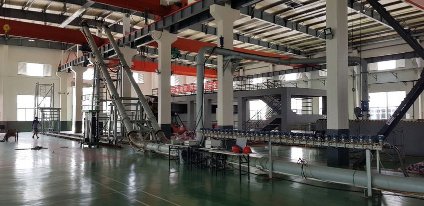
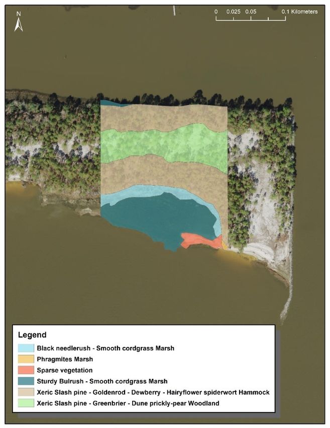
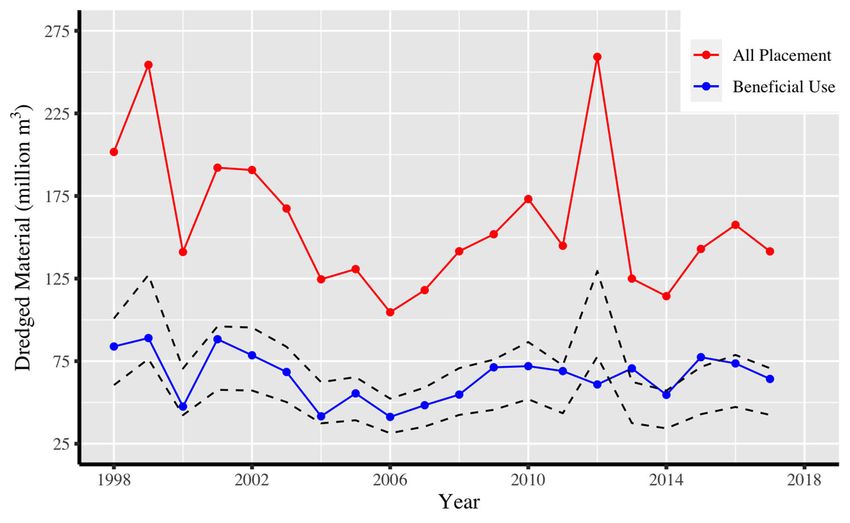
© 2021 Western Dredging Association WEDA Journal of Dredging, Vol. 19, No. 2

where the swamps and marshes were assumed to have none. In addition, the proximity to shipping and nearshore
industrial activities bolstered newly created land values.
The concept of dredged material beneficial use became more formalized during the 1970s and 1980s.
Environmental regulations made sediment disposal more complicated and increased sediment disposal costs,
particularly when associated with constructing new dredged material placement facilities. These societal and
economic pressures made beneficial use more attractive. Construction of many successful beneficial use projects
helped extend existing placement capacity of existing facilities while new solutions were pursued. This period
culminated with the Engineer Manual 1110-2-5026 (USACE 1987) that summarized a host of successful
strategies for dredged material beneficial use. Funded by the Dredging Operations and Environmental Research
(DOER) program, the USACE recently revisited several USACE beneficial use projects constructed in the late
1970s to document their long-term successes and trajectories; these projects were initially documented by
Newling and Landin (1985). The findings show that all projects produced ecological (e.g., habitat development)
or engineering (e.g., shoreline resiliency) benefits. Drake Wilson Island is one successful example that continues
to provide benefits, as summarized in the Engineering With Nature Atlas Volume 2
(https://ewn.el.erdc.dren.mil/atlas.html). The long-term success demonstrated by this project demonstrates that
the technical capacity to successfully implement beneficial use has been available for decades.

With the successful application of beneficial use, dredged material drew increasing interest in the 1990s as a
potential resource, especially in urban areas where soil sources are scarce. For example, the New Jersey
Department of Transportation (NJDOT) conducted numerous demonstration projects related to the use of
dredged sediment for mine reclamation, highway embankment construction, and other uses (Yozzo et al. 2004).
They also evaluated a host of treatment technologies that could reduce chemical concentrations in dredged
material to levels suitable for different beneficial uses.

Despite a long history of successful beneficial use projects (see for example Bridges et al. [2018] and
https://budm.el.erdc.dren.mil/), beneficial use is not practiced on a widespread and consistent basis. Bridges
(2018) asked, “What would it take to reach 100% beneficial use?” This paper investigates potential feasibility,
cost, and institutional barriers that currently restrict achieving this goal and identifies potential solutions for
overcoming these barriers and expanding beneficial use. Portions of this paper are excerpted from a forthcoming
update on the PIANC (2009) international standard of practice on sediment beneficial use.

 CATEGORIZING BENEFICIAL USES AND BENEFICIAL USE TRENDS
Dredged material consists primarily of super-saturated granular particles typical of most soils and sediment—
gravel, sand, silt, and clay. Although some dredged material contains elevated concentrations of chemical
contaminants, the vast majority of navigational dredged material does not. Thus, almost any need for additional
soil or sediment provides a potential opportunity for using dredged material.

PIANC (2009) defines sediment beneficial use as any use of dredged material rather than mere disposal is
regarded as use. This definition allows consideration of the widest range of options available to the port
operator, contractor or other proposer seeking to use dredged material from dredging operations. The Central
Dredging Association (CEDA 2019) defined sediment beneficial use as the use of dredged or natural sediment
in applications that are beneficial and in harmony to human and natural development. While also broad, this
definition focuses on sediment uses that benefit society and the natural environment. It places a greater burden
on decision makers to consider societal and ecological benefits of sediment use. USACE (1987), USEPA and
USACE (2007a) and USACE (2015), and Childs (2015) identified multiple beneficial use categories in an
attempt to better understand and expand beneficial use opportunities. Those uses are listed in Table 1. Here, we
define beneficial use as using dredged sediment to achieve additional benefits beyond the purposes related to
its removal, including other economic, environmental, or social benefits.

While these approaches categorize beneficial use by application or technology, the USACE Regional Sediment
Management (RSM) Database (USACE 2020) uses a simplified version of Child’s (2015) approach and
categorizes beneficial use based on location where sediment is applied rather than type: i.e., beach, in-river, and

 21
© 2021 Western Dredging Association WEDA Journal of Dredging, Vol. 19, No. 2

 Table 1. Comparison of attempts to categorize beneficial use alternatives by previous efforts.
 USEPA and USACE (2007a)
 USACE (1987) Childs (2015)
 and USACE (2015)
 Habitat restoration and Upland placement for ecological
 Habitat development
 development habitat
 Beach or nearshore placement
 Beach nourishment Beach nourishment for shoreline protection or beach
 nourishment
 Placement for upland land
 Parks and recreation Parks and recreation
 development
 Agriculture, forestry, and Agriculture, forestry, horticulture, Shallow water placement for
 horticulture and aquaculture wetland, marsh, or habitat
 Strip mine reclamation and solid Strip-mine reclamation and solid
 Unconfined aquatic placement
 waste management waste management
 Construction/industrial
 Construction and industrial use Island placement for benefits
 development
 Ocean placement for beneficial
 Multiple purpose Multiple-purpose activities
 use
 Material transfer Upland placement for soil reuse
 Shoreline stabilization and Confined in-water placement for
 erosion control beneficial purpose
 Aquaculture

littoral; open water, upland, and wetland. Child’s categories are used in the Great Lakes Beneficial Use manual
(GLDT 2020).

USEPA and USACE (2007a) estimated that only 20-30% of the total volume dredged in the US is being used
beneficially. Unfortunately, the data to differentiate beneficial use rates for channel maintenance as compared
to channel deepening or other new work are not available. Since 1997, USACE has tracked dredge volumes and
sediment beneficial use (USACE 2020). Figure 1 shows annual dredged volumes and beneficial use volumes
from 1997 through 2017. The data show an average of 38% beneficial use for sediment removed from federal
navigation channels between 1998 and 2017. For 2004-2006, beneficial use is closer to 30%, reasonably
consistent with the conclusions drawn by USEPA and USACE (2007a). Other years are closer to 40% or 50%
beneficial use.

While the volume of beneficial use in the US, 50 to 80 million cubic meters (MCM) annually, is impressive,
Figure 1 also shows the potential for redirecting an additional 80 MCM annually to beneficial uses in lieu of
disposal. The National Research Council (1994) estimated that only 5% of maintenance dredged material in the
US is unsuitable for open water placement. More recent or specific citable data were not identified, but it is
believed that only a very small portion would have restrictions on beneficial use or require treatment because of
sediment contamination.

Encouraging the expansion of beneficial use will be especially important in upcoming decades, as dredged
material placement options reach capacity in many areas and open water placement is under increasing scrutiny.
Societal pressures, regulations, and space limitations make open water disposal and the permitting and
construction of new placement facilities increasingly difficult and expensive. For example, the closure of the
“Mud Dump” disposal site in New York / New Jersey Harbor in 1992 resulted in a dredging crisis for the State
of New Jersey that spurred the region toward beneficial use (Maher et al. 2013). The closure of this open water
disposal site put into jeopardy New Jersey’s ability to conduct maintenance dredging and to implement new
capital projects, like the planned deepening of entrance channels to the Port of New York and New Jersey. This
eventually led to numerous policy changes, including regulatory overhaul and the establishment of policies that
supported innovative techniques to manage dredged material, such as a greater investment in beneficial use.
More recently, the State of Ohio banned open water disposal in Lake Erie starting July 2020, also leading to

 22
You can also read