Microfluidic Single-Cell Manipulation and Analysis: Methods and Applications - MDPI
←
→
Page content transcription
If your browser does not render page correctly, please read the page content below
micromachines

Review
Microfluidic Single-Cell Manipulation and Analysis:
Methods and Applications
Tao Luo 1,† , Lei Fan 1,† , Rong Zhu 2 and Dong Sun 1,3, *
 1   Department of Biomedical Engineering, City University of Hong Kong, Hong Kong, China;
     taoluo4-c@my.cityu.edu.hk (T.L.); leifan-c@my.cityu.edu.hk (L.F.)
 2   State Key Laboratory of Precision Measurement Technology and Instruments, Department of Precision
     Instrument, Tsinghua University, Beijing 100084, China; zr_gloria@mail.tsinghua.edu.cn
 3   Shenzhen Research Institute of City University of Hong Kong, Shenzhen 518057, China
 *   Correspondence: medsun@cityu.edu.hk; Tel.: +852-3442-8405
 †   These authors contributed equally to this work.

 Received: 19 December 2018; Accepted: 30 January 2019; Published: 1 February 2019

 Abstract: In a forest of a hundred thousand trees, no two leaves are alike. Similarly, no two cells in a
 genetically identical group are the same. This heterogeneity at the single-cell level has been recognized
 to be vital for the correct interpretation of diagnostic and therapeutic results of diseases, but has
 been masked for a long time by studying average responses from a population. To comprehensively
 understand cell heterogeneity, diverse manipulation and comprehensive analysis of cells at the
 single-cell level are demanded. However, using traditional biological tools, such as petri-dishes and
 well-plates, is technically challengeable for manipulating and analyzing single-cells with small size
 and low concentration of target biomolecules. With the development of microfluidics, which is a
 technology of manipulating and controlling fluids in the range of micro- to pico-liters in networks of
 channels with dimensions from tens to hundreds of microns, single-cell study has been blooming for
 almost two decades. Comparing to conventional petri-dish or well-plate experiments, microfluidic
 single-cell analysis offers advantages of higher throughput, smaller sample volume, automatic
 sample processing, and lower contamination risk, etc., which made microfluidics an ideal technology
 for conducting statically meaningful single-cell research. In this review, we will summarize the
 advances of microfluidics for single-cell manipulation and analysis from the aspects of methods and
 applications. First, various methods, such as hydrodynamic and electrical approaches, for microfluidic
 single-cell manipulation will be summarized. Second, single-cell analysis ranging from cellular
 to genetic level by using microfluidic technology is summarized. Last, we will also discuss the
 advantages and disadvantages of various microfluidic methods for single-cell manipulation, and then
 outlook the trend of microfluidic single-cell analysis.

 Keywords: microfluidics; single-cell manipulation; single-cell analysis

1. Introduction
     Over the past few decades, cellular heterogeneity has gradually been emphasized on fundamental
biological and clinical research as numerous novel tools/methods for single-cell analysis have
emerged [1]. Phenotype heterogeneity between genetically identical cells plays an important
role in tumor metastasis [2], drug resistance [3], and stem cell differentiation [4]. For instance,
different responses of individual cells to drugs cause the emergence of drug-resistant cells, but only
a small percentage (0.3%) of these cells have the ability for tumor recurrence [5]. However, cellular
heterogeneity has been masked for a long time because previous biological studies are mainly based
on manipulating and analyzing cells at the bulk-scale, which interpreted all phenomena by using

Micromachines 2019, 10, 104; doi:10.3390/mi10020104                    www.mdpi.com/journal/micromachines
Micromachines 2019, 10, 104                                                                          2 of 31

average results. Until today, single-cell study still has been recognized as the most straightforward way
to performance comprehensive heterogeneity study from the aspects of cellular behavior to genetic
expression. Comprehensive single-cell study heavily relies on the use of high-throughput and efficient
tools for manipulating and analyzing cells at the single-cell level.
      Single-cell analysis is technically more difficult than bulk-cell analysis in terms of the sizes
of cells and the concentrations of cellular components. The majority of cells, such as mammalian
and bacteria cells, have sizes at the scale of microns. Therefore, manipulation of those cells at the
single-cell level becomes difficult when using traditional biological tools, such as petri-dishes and
well-plates. Additionally, most of the intracellular, extracellular components are presented in very
small concentrations and have a wide range of concentrations, which demand highly sensitive and
specific detection methods. Many single-cell analysis applications require a single-cell isolation first,
and multi-well plates are commonly used in most biological labs for single-cell isolation, which is low in
efficiency and labor-intensive [6]. While the use of robotic liquid handling workstation reduces the labor
intensity, it is very expensive for some labs to afford it [7]. Flow cytometry or laser scanning cytometry,
which rapidly screens fluorescently labeled cells in a flow, has been developed and recognized as a
golden standard for single-cell analysis for a long time [8]. Taking flow cytometry as an example,
although they are automatic, capable of multiple detections, and efficient in single-cell sorting, they are
bulky, mechanically complicated, expensive, and demanding for relatively large sample volumes.
Besides, they can only be used for analyzing cells at one time-point. Hence, it is impossible to use
flow cytometry for continuously monitoring cell dynamics. Owing to the capability of manipulating
and controlling fluids in the range of micro to pico-liters, microfluidics has been developed as a
platform-level and continuously evolving technology for single-cell manipulation and analysis for
about two decades.
      Microfluidics has many incomparable advantages over conventional techniques.
Firstly, the microfluidic chip can be flexibly designed to fulfill the demands of diverse single-cell
manipulation and analysis tasks. For instance, single-cell manipulation can be achieved by using either
passive [9–11] or active [12,13] method, and single-cell analysis can be achieved by implementing
either optical [14,15] or electrochemical [16,17] method. Secondly, miniaturized microfluidic systems
work can work with very small volume (down to pL level) of liquid, which helps to reduce sample loss
and decrease dilution, resulting in highly sensitive detections. Hence, numerous microfluidics-based
biosensors have been developed. Thirdly, microfluidics allows for high-throughput parallel
manipulation and analysis of the sample, which is beneficial for the statistically meaningful single-cell
analysis. Fourthly, multiple functionalities are easily integrated on the same chip, which allows
for automation, and can also avoid contamination and errors introduced by manual operations.
Many single-cell studies require single-cell capture/isolation, and different microfluidic methods,
such as hydrodynamic [11,18,19], electrical [20], optical [21], magnetic [22], and acoustic [23] methods,
have been developed. Various detection methods, such as fluorescence microscopy, fluorometry
and mass spectroscopy, can be combined with microfluidic systems for single-cell analysis from cell
morphology to secreted proteins. As for either single-cell manipulation or single-cell analysis, it is
hard to obtain a comprehensive result by merely using one method. Therefore, two or more methods
are usually combined into a microfluidics system for various single-cell studies [24,25].
      While reviews about single-cell manipulation and analysis by using microfluidics are reported
almost every year, systematic summarization of this area can give valuable references to both academic
and industrial fields. In this review, we mainly focus on microfluidic technologies for single-cell
manipulation analysis from the aspects of methods and applications. We highlight methods that are
promising for future development, which are discussed in terms of single-cell manipulation including
hydrodynamic, electrical, optical, magnetic, acoustic, and micro-robots assisted methods. We also
highlight applications that are accepted by academic and industrial fields, which are discussed in
terms of single-cell analysis from cellular to protein analysis. Last, we also discuss the technology and
application trend for microfluidics based single-cell analysis.
Micromachines 2019, 10, 104                                                                                            3 of 31

2. Microfluidic Single-Cell Manipulation
     With the development of Microelectromechanical Systems (MEMS) technology, many micro-scale
devices have been fabricated for bioanalysis at single-cell resolution. As a powerful technology
to perform precise fluidic control, microfluidics has attracted great interests for various single-cell
manipulations, such as single-cell encapsulation and single-cell trapping (Table 1). Nowadays, various
methods, including hydrodynamic, electrical, optical, acoustic, magnetic, and micro-robotic method,
were used for diverse microfluidic single-cell manipulations.
                                      Table 1. Various single-cell manipulations.

                 Manipulations                                           Descriptions
        Single-cell encapsulation [26–30]            Entrapping single cells in isolated microenvironments
                                               Separating homogenous populations of cells from heterogeneous
          Single-cell sorting [12,31–33]
                                                            populations at the single-cell resolution
          Single-cell trapping [34–36]       Immobilizing single cells from bulk cells on the designated positions.
          Single-cell isolation [37,38]                Pick or isolate single cells from bulk populations
            Single-cell rotation [39]                             Rotating targeted single cells
           Single-cell pairing [20,40]        Positioning two homo- or heterotypic cells in proximity or contact
           Single-cell patterning [23]        Positioning single cells on a substrate with defined spatial selection
           Single-cell stretching [41]                Using external forces to deform targeted single cells
         Single-cell transportation [42]                      Moving cells at the single-cell level
            Single-cell lysis [43,44]                       Breaking down the targeted single cells
                                              Applying external physical/chemical/biological cues to stimulate
        Single-cell stimulation [19,45,46]
                                                                       targeted single cells

2.1. Hydrodynamic Method
      Compared with other single-cell manipulation methods, the hydrodynamic method is much
simpler and higher throughput. Hydrodynamic manipulation mainly relies on the interaction among
microstructure, fluid, and cells. This technique has the advantages of high throughput, less damage to
cells, mature chip fabrication crafts, and easy integration with other analysis functionalities. Based on
the used mechanisms, the hydrodynamic method can be categorized into droplet microfluidics,
inertial microfluidics, vortex, and mechanical methods.

2.1.1. Droplet Microfluidics
      Droplet microfluidics has attracted more and more interests for its capability to encapsulate
cells and many reagents in a microscale environment [47]. It is also a powerful technique for
high-throughput single-cell encapsulation. The size, shape, and uniformity of droplets can be precisely
controlled. This method usually requires two immiscible fluids to create monodispersed water-in-oil
(w/o) microdroplets with sizes that range from the submicron to several hundreds of microns [48].
As shown in Figure 1, three types of microfluidic droplet generation approach usually used: T-junction,
flow focusing, and co-flow [28]. However, the basic principles of these three approaches are the
same. One fluid becomes the dispersed phase to form the droplets and the other fluid becomes the
continuous phase to separate the droplets. As illustrated in Figure 1a, Zhang et al. integrated T-junction
structure with droplet inspection, single-cell droplet sorting and exporting on one chip to analyze DNA
and RNA at both gene-specific and whole-genome levels [49]. Zilionis et al. utilized flow focusing
structure, shown in Figure 1b, to conduct single-cell barcoding and sequencing [27]. Adams et al.
encapsulated multi-component in one droplet using co-flow method, as shown in Figure 1c [50].
All three approaches require to control each fluid phase precisely, which usually make the system
a little bit complex. Khoshmanesh et al. proposed a novel mechanism for generating microscale
droplets of aqueous solutions in oil using a highly porous PDMS sponge [51]. Compared to the existing
microfluidic droplet generation approach, the sponge-based approach is a self-sufficient, stand-alone
device, which can be operated without using pumps, tubes, and microfluidic skills. Single-cell is
randomly encapsulated in each droplet, and the number of cells in each droplet follows nonuniform
poisson distribution. Therefore, the cell suspension usually requires to be highly diluted before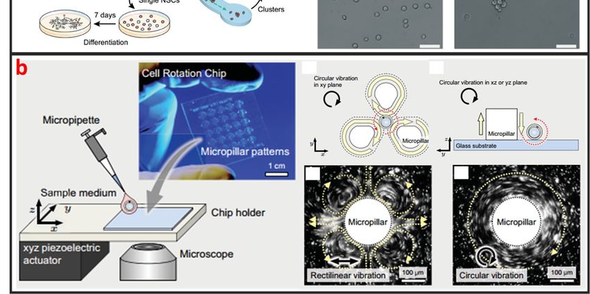
Micromachines 2019, 10, 104                                                                                              4 of 31

     Micromachines 2019, 10, x FOR PEER REVIEW                                                                 4 of 31
encapsulation to ensure only one single cell in one droplet. However, this procedure leads to reagent
    leads
waste andtodegrades
              reagent waste     and degrades
                        throughput            throughput
                                        because          because
                                                most of the       most of
                                                            generated     the generated
                                                                        droplets   do not droplets
                                                                                           contain do  not cells.
                                                                                                    single
    contain  single cells. Several  methods have been developed to overcome  this limitation. For
Several methods have been developed to overcome this limitation. For example, post-sorting based  example,
    post-sorting based on property differences can be applied to enhance single-cell encapsulation
on property   differences can be applied to enhance single-cell encapsulation efficiency. Moreover, this
    efficiency. Moreover, this technique is hampered by some other drawbacks. For instance, the cell
technique is hampered by some other drawbacks. For instance, the cell culture in droplet is suspended,
    culture in droplet is suspended, which means that the culture of adherent cell in droplet is difficult.
which  means that the culture of adherent cell in droplet is difficult. Introducing/picking components
    Introducing/picking components in/out of droplets without risking cross-contamination among cell-
in/out  of droplets
    contained        without
                droplets         risking cross-contamination among cell-contained droplets is difficult.
                          is difficult.

          Figure
     Figure       1. Three
              1. Three     types
                        types  of of methodsand
                                  methods     anddesigns
                                                   designs for
                                                           formicrofluidic
                                                               microfluidicsingle-cell droplet
                                                                             single-cell       generation.
                                                                                          droplet          Adapted
                                                                                                   generation.  Adapted
          by   permission   from   Reference  [28], copyright  Royal  Society  of Chemistry    2015.
     by permission from Reference [28], copyright Royal Society of Chemistry 2015. (a) T-junction    (a) T-junction
          microchannel based droplet generation for encapsulating single cells for cultivation and genomic
     microchannel     based droplet generation for encapsulating single cells for cultivation and genomic
          analysis. Adapted by permission from reference [49], under the Creative Commons Attribution
     analysis. Adapted by permission from reference [49], under the Creative Commons Attribution License
          License 2017. (b) Flow-focusing for encapsulating a single cell and a barcoding hydrogel bead in a
     2017. (b) Flow-focusing for encapsulating a single cell and a barcoding hydrogel bead in a droplet for
          droplet for single-cell barcoding and sequencing. Adapted by permission from Reference [27],
     single-cell  barcoding and sequencing. Adapted by permission from Reference [27], copyright Nature
          copyright Nature Publishing Group 2017. (c) Co-flow for preparing multiple component double
     Publishing   Group
          emulsions.       2017.by
                       Adapted    (c)permission
                                      Co-flow for
                                                frompreparing
                                                      Referencemultiple  component
                                                                [50], copyright Royal double    emulsions.
                                                                                        Society of ChemistryAdapted
                                                                                                             2012.   by
     permission from Reference [50], copyright Royal Society of Chemistry 2012.
     2.1.2. Inertial Microfluidics
2.1.2. Inertial Microfluidics
            As a cross-streamline cell manipulation method, inertial microfluidics is based on using inertial
      As a cross-streamline
      forces  under certain high cell manipulation
                                   flow                method, inertial
                                          rates to continuously    focus andmicrofluidics
                                                                              sort cells with is based   onsizes
                                                                                                 different  using   inertial
                                                                                                                  and
forces  underascertain
      shapes,            highinflow
                  illustrated        rates
                                 Figure  2ato continuously
                                            [52]. The inertial focus   and sorthas
                                                                microfluidics   cells
                                                                                   thewith   different
                                                                                        advantages    of sizes
                                                                                                         simpleand
                                                                                                                 chipshapes,
      structure, in
as illustrated    ultra-high
                     Figure 2athroughput,   and less microfluidics
                                [52]. The inertial    damage to cellshaswhich  is beneficial to
                                                                           the advantages      ofmaintain   highstructure,
                                                                                                  simple chip     cell
      survival
ultra-high      rate for downstream
             throughput,                 culture. to
                             and less damage       However,    intercellular
                                                     cells which             interaction
                                                                    is beneficial           can greatly
                                                                                  to maintain             reduce
                                                                                                  high cell        the rate
                                                                                                             survival
      efficiency of cell
for downstream           manipulation
                      culture.  However,by using  inertial microfluidics.
                                             intercellular  interaction Therefore,
                                                                           can greatlyit isreduce
                                                                                            only applicable  to workof cell
                                                                                                    the efficiency
      under a certain cell concentration. This method is usually used for separating single circulating cancer
manipulation by using inertial microfluidics. Therefore, it is only applicable to work under a certain
cell concentration. This method is usually used for separating single circulating cancer cells from
blood cells, and it usually requires pre-dilution of blood samples [53,54]. Nathamgari et al. used
Micromachines 2019, 10, 104 5 of 31
Micromachines 2019, 10, x FOR PEER REVIEW 5 of 31
cells from
inertial blood cells,to
microfluidics and it usually
separate therequires pre-dilution
single neural cells of
andblood samples
clusters from[53,54]. Nathamgari
a population et al.
of chemically
used inertial microfluidics to separate the single neural cells and clusters from a population of
dissociated neurospheres shown in Figure 2a [55]. In contrast to previous sorting technologies that
chemically dissociated neurospheres shown in Figure 2a [55]. In contrast to previous sorting
require operating at high flow rates, they implemented a spiral microfluidic channel in a novel-focusing
technologies that require operating at high flow rates, they implemented a spiral microfluidic channel
regime that occurs at relative lower flow rates. The curvature-induced Dean’s force focused the smaller
in a novel-focusing regime that occurs at relative lower flow rates. The curvature-induced Dean's
single cells towards
force focused the inner
the smaller wall
single cellsand the larger
towards clusters
the inner towards
wall and the center
the larger clustersoftowards
channel.
the center
of channel.
2.1.3. Vortex
2.1.3. Vortex
Vortex based method is based on generating a time-averaged secondary flow known as steady
streaming eddies
Vortex based[56,57],
methodwhich
is basedis generated
on generatingby the interaction between
a time-averaged secondary frequency
flow known oscillations
as steady of the
fluid medium
streaming and [56,57],
eddies fixed cylinder
which isingenerated
a microchannel to trap single
by the interaction cells.frequency
between Therefore, the vortex
oscillations of approach
the
is fluid medium
also called and fixedhydrodynamic
single-cell cylinder in a microchannel
tweezer. Into2006,trap single cells.
Lutz et al. Therefore,
used motile thephytoplankton
vortex approachcells to
is also called
measure single-cell
the trapping hydrodynamic
location tweezer.
and trapping forceIn 2006, Lutz et
[34]. They al. used
proved motile
that eachphytoplankton cells
eddy traps a single-cell
to measure the trapping location and trapping force [34]. They proved that each
near the eddy center, precisely at the channel midplane, and the trapped cell is completely suspended eddy traps a single-
bycell
thenear
fluidthe eddy center,
without touching precisely at the
any solid channelFurthermore,
surface. midplane, and thethe trappedforce
trapping cell is
arecompletely
comparable to
suspended by the fluid without touching any solid surface. Furthermore, the trapping force are
dielectrophoretic force and optical tweezer force, whereas the trap environment is within physiological
comparable to dielectrophoretic force and optical tweezer force, whereas the trap environment is
limits of shear in arterial blood flow. Thus, the hydrodynamic tweezer does not limit the cell type,
within physiological limits of shear in arterial blood flow. Thus, the hydrodynamic tweezer does not
shape, density, or composition of the fluid medium. As shown in Figure 2b, Hayakawa et al. adopted
limit the cell type, shape, density, or composition of the fluid medium. As shown in Figure 2b,
three
Hayakawa et al. arranged
micropillars in a triangular
adopted three micropillarsconfiguration
arranged in aand an xyz piezoelectric
triangular configuration actuator
and an xyz to apply
thepiezoelectric
circular vibration
actuator to apply the circular vibration to generated vortex for trapping and 3D rotating [58].
to generated vortex for trapping and 3D rotating mouse oocytes single-cell
Additionally,
mouse oocytes they measured
single-cell the
[58]. rotational speeds
Additionally, in the focal
they measured and vertical
the rotational planes
speeds focal±and
as 63.7
in the 4.0◦ ·s−1
and ◦
3.5 ±planes − 1
2.1 ·s as ,63.7
respectively.
vertical ± 4.0°∙s−1 and 3.5 ± 2.1°∙s−1, respectively.
Figure2.2.Inertial
Figure Inertial and
and vortex
vortex microfluidic
microfluidicsingle-cell manipulation
single-cell manipulationandand
some designs.
some (a) Inertial
designs. (a) Inertial
microchannel to separate single-cell from cell cluster. Adapted by permission from References [52,55],
microchannel to separate single-cell from cell cluster. Adapted by permission from References [52,55],
copyrightRoyal
copyright Royal Society
Society of
of Chemistry
Chemistry20092009andand2015. (b) (b)
2015. Vortex generated
Vortex by micropillar
generated to rotate
by micropillar to rotate
single-cell. Adapted by permission from Reference [58], under the Creative Commons Attribution
single-cell. Adapted by permission from Reference [58], under the Creative Commons Attribution
License 2015.
License 2015.
Micromachines 2019, 10, 104 6 of 31
2.1.4. Mechanical Method
Mechanical method for single-cell manipulation mainly refers to the use of membrane pump,
microvalve, and microstructures.
Micromachines 2019, 10, x FOR PEER REVIEW 6 of 31
• Microvalve
2.1.4. Mechanical Method
Having the advantages of small size, fast response, and simple fabrication, the active microvalve
Mechanical method for single-cell manipulation mainly refers to the use of membrane pump,
is widely used in the manipulation of single cells [29]. Multilayer soft lithography, which is the
microvalve, and microstructures.
basement of microvalve,
● Microvalve was first developed by Quake’s group [59]. They used this technique to build
active microfluidic
Having the systems
advantages containing on-off
of small size, valvesand
fast response, andsimple
switching valves.
fabrication, Themicrovalve
the active invention of these
is widely
valves made used in the
it possible to manipulation
realize highofdensity
single cells [29].control
fluid Multilayerand soft lithography,functional
large-scale which is theintegration
basement of microvalve, was first developed by Quake’s group [59]. They used this technique to
on a chip, which is a milestone in the development of microfluidic technology. Thus, this kind of
build active microfluidic systems containing on-off valves and switching valves. The invention of
microvalvethese is valves
calledmade “Quake valve”.
it possible to The structure
realize of “Quake
high density valve”
fluid control andconsists of afunctional
large-scale vertically crossed
flow layer and a control
integration on a chip,layer,
which between which
is a milestone in the a deformable
development film is formed.
of microfluidic When
technology. Thus,the
this pressure is
kind of microvalve
applied through the control is called
layer,“Quake valve”.
the film The structure
deforms of “Quake
and sticks to the valve”
bottomconsists of a vertically
surface of flow channel to
block thecrossed
flow in flow layer and a control layer, between which a deformable film is formed. When the pressure
the flow layer. On the contrary, when the control layer does not exert pressure or
is applied through the control layer, the film deforms and sticks to the bottom surface of flow channel
apply a relatively
to block thesmallflow inpressure, the On
the flow layer. flowthelayer appears
contrary, when the to control
be open ordoes
layer semi-open. Fluidigm
not exert pressure or Company
of UnitedapplyStates developed
a relatively a single-cell
small pressure, the flowautomatic
layer appears pretreatment system called
to be open or semi-open. FluidigmC1 Single-Cell Auto
Company
of United
Prep System basedStates developed
on this a single-cell
technology, whichautomatic pretreatment system
can automatically separate called
96C1 Single-Cell cells
suspended Auto at one time.
Prep System based on this technology, which can automatically separate 96 suspended cells at one
At present, the system has been used in many universities and research institutions in the world for
time. At present, the system has been used in many universities and research institutions in the world
single-cellforgenomics research.research.
single-cell genomics ShalekShalek
et al.etuses this
al. uses thissystem
system totoisolate
isolate single-cell
single-cell and conduct
and conduct RNA- RNA-seq
libraries seq
prepared
libraries from
prepared over from1700
over primary
1,700 primary mouse
mousebone-marrow-derived
bone-marrow-derived dendritic dendritic cells shown in
cells shown
in Figure
Figure 3 [60]. While 3 [60]. While microvalves
microvalves offer manyoffer advantages,
many advantages, theirtheir external
external controldevices
control devices are
are extremely
complex extremely complex and cumbersome. Thus, the external operation of large-scale integrated
and cumbersome. Thus, the external operation of large-scale integrated microfluidic chips
microfluidic chips based on microvalves must be simplified and adapted to the working habits of
based onbiological
microvalves must be simplified and adapted to the working habits of biological researchers.
researchers.
Figure 3.Figure 3. Microfluidic valve single-cell isolation and a design Adapted by permission from References
Microfluidic valve single-cell isolation and a design Adapted by permission from
[29,60], copyright Nature Publishing Group 2017 and 2014.
References [29,60], copyright Nature Publishing Group 2017 and 2014.
● Microstructure
• Microstructure
The method based on microstructures, such as microtraps and microwells, only requires
The researcher
method based onmicrostructures
to design microstructures, whosesuch
sizesasaremicrotraps
similar to theand
size microwells,
of a single cell.only
Afterrequires
injecting researcher
to designcells into microfluidicwhose
microstructures chip, cells floware
sizes along the streamlines
similar of the
to the size oflaminar
a single flow, andAfter
cell. can beinjecting
trapped cells into
by shearing force generated by microstructure. Current microstructure for single-cell trap include U-
microfluidic chip, cells flow along the streamlines of the laminar flow, and can be trapped by shearing
shaped, S-shaped, and microwell based traps.
force generated by microstructure.
U-shaped Currentfirstly
microtrap was demonstrated microstructure
by Di Carlo et for
al. tosingle-cell trapsingle
trap and culture include
Hela U-shaped,
S-shaped,cells
and[61].
microwell based
The U-shaped traps. was fabricated by polydimethylsiloxane (PDMS), bonded with
structure
glass and
U-shaped there was awas
microtrap gap between the trap and
demonstrated the glass
firstly substrate
by Di Carloforetincreasing
al. to traptheand
single-cell
culturetrapsingle Hela
efficiency. Then, the U-shaped microtrap was modified by Wlodkowic et al. to add three gaps in the
cells [61]. The U-shaped structure was fabricated by polydimethylsiloxane (PDMS), bonded with
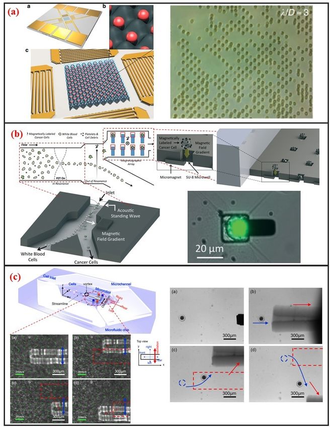
edge of U-shaped groove for increasing the cell viability [19]. In the last years, Tran et al. designed
glass andU-shaped
there was a gap
micro sievebetween
comprisedthe trap and
semicircular the
arcs glassatsubstrate
spaced for and
specific offsets increasing
distance asthe single-cell trap
shown
efficiency.in Then,
Figure the U-shaped
4a [62]. microtrap
Using this micro sieve,was
theymodified by Wlodkowic
realized label-free and rapidet al. tobreast
human add three
cancer gaps in the
single-cell isolation
edge of U-shaped groovewithforup to 100% trapping
increasing the cellyield and >95%[19].
viability sequential
In theisolation efficiency.
last years, TranLuo et et
al. designed
al. fabricated a high throughput single-cell trap and culture platform to investigate clonal growth of
U-shaped micro sieve comprised semicircular arcs spaced at specific offsets and distance as shown
in Figure 4a [62]. Using this micro sieve, they realized label-free and rapid human breast cancer
single-cell isolation with up to 100% trapping yield and >95% sequential isolation efficiency. Luo et al.
fabricated a high throughput single-cell trap and culture platform to investigate clonal growth of
arrayed single-cells under chemical/electrical stimuli for the week-scale period [63]. To achieve
Micromachines 2019, 10, 104 7 of 31
Micromachines 2019, 10, x FOR PEER REVIEW 7 of 31
arrayed single-cells
deterministic single-cell under chemical/electrical
capture in large-sizedstimuli for the week-scale
microchambers, periodsieve
a U-shaped [63]. with
To achieve
a 5µm-thick
deterministic
bottom single-cell
microchannel wascapture
used to in capture
large-sized microchambers,
a single-cell, a U-shaped
and two streamsieve with arms
focusing a 5µm-thick
were placed
bottom
in front of microchannel was usedcapture
the sieve to enhance to capture a single-cell,
efficiency. Zhangand et
two
al.stream focusing arms
demonstrated were placed
a handheld single-cell
in front of the sieve to enhance capture efficiency. Zhang et al. demonstrated a handheld single-cell
pipette, which allows for rapid single-cell isolation from low concentration cell suspension, by using a
pipette, which allows for rapid single-cell isolation from low concentration cell suspension, by using
U-shaped microtrap, as shown in Figure 4b [37].
a U-shaped microtrap, as shown in Figure 4b [37].
S-shaped microstructure is based on the different fluidic resistance in different position of
S-shaped microstructure is based on the different fluidic resistance in different position of
microchannel.
microchannel.The TheS-shaped microstructurewas
S-shaped microstructure was firstly
firstly reported
reported by Tan
by Tan et al.ettoal. to and
trap traprelease
and release
microbeads
microbeads[64].[64].
After microbead
After microbead trapping, one objective
trapping, bead bead
one objective couldcould
be release by optical
be release by microbubbles.
optical
In recent years, S-shaped
microbubbles. In recent microstructure
years, S-shaped was also further
microstructure optimized.
was Kim.
also further et al. proposed
optimized. Kim. et a al.simple,
proposed
efficient a simple,
S-shaped efficient array
microfluidic S-shaped chipmicrofluidic
integrated witharraya chip integrated
size-based with a size-based
cell bandpass cellThe key
filter [65].
bandpass filter
advancement [65].chip
to this The is
key advancement
not to this of
the optimization chip is not the trap,
single-cell optimization
but the of single-celloftrap,
capability but cells
trapping
the capability of trapping cells within a specific range of sizes. Mi et al. combined
within a specific range of sizes. Mi et al. combined U-shape and S-shape, which is named m-by-n U-shape and S- trap
shape, which is named m-by-n trap units, to pattern single Hela cells, as shown in Figure 4c [10]. Each
units, to pattern single Hela cells, as shown in Figure 4c [10]. Each unit has two roundabout channels
unit has two roundabout channels and one capture channel. Different from previous S-shaped
and one capture channel. Different from previous S-shaped microchannels, this structure enables each
microchannels, this structure enables each trap unit to be treated equally and independently.
trapTherefore,
unit to beany
treated equally
unit can and independently.
be selected for finalizing theTherefore,
geometricany unit canofbe
parameters theselected for finalizing
fluidic channels to the
geometric parameters
satisfy the of the fluidic channels to satisfy the capture condition.
capture condition.
Figure
Figure 4. Microstructure
4. Microstructure basedsingle-cell
based single-cellmanipulation
manipulation methods
methods and
andsome
sometypical
typicaldesigns.
designs.(a)(a)
Micro-
Micro-sieve
sieve to isolate floating single cancer cell under continuous flow. Adapted by permission
to isolate floating single cancer cell under continuous flow. Adapted by permission from Reference from [62],
Reference [62], copyright Royal Society of Chemistry 2016. (b) A microfluidic pipette tip with a micro-
copyright Royal Society of Chemistry 2016. (b) A microfluidic pipette tip with a micro-hook for trapping
hook for trapping and releasing a single cell. Adapted by permission from Reference [37], copyright
and releasing a single cell. Adapted by permission from Reference [37], copyright Royal Society of
Royal Society of Chemistry 2016. (c) Microchannel to trap single-cell based on fluidic circuit. Adapted
Chemistry 2016. (c) Microchannel to trap single-cell based on fluidic circuit. Adapted by permission from
Reference [10], copyright Royal Society of Chemistry 2016. (d) A dual-microwell design for the trap
and culture of single cells. Adapted by permission from Reference [66], copyright Royal Society of
Chemistry 2015.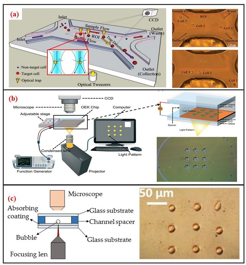
Micromachines 2019, 10, 104                                                                        8 of 31

     Microwell is another passive microstructure for single-cell trapping. This structure is mainly
based on the size match of the single cell and microwell. When the diameter of microwell approaches
the diameter of a single cell, redundant cells will be wash out and one single cell settled down to one
microwell can be trapped. After injecting cell suspension to microfluidic channel, cells will sediment
down and go into microwells. When the depth of the microwell is deep enough, vortex generates
inside the microwell and single cells can be trapped firmly. Most of current microwells were fabricated
by soft lithography. In 2004, Revzin et al. developed a cytometry platform for characterization and
sorting of individual leukocytes [32]. Poly (ethylene glycol) (PEG) was employed to fabricate arrays
of microwells composed of PEG hydrogel walls and glass substrates. PEG micropatterned glass
surfaces were further modified with cell-adhesive ligands, poly-L-lysine, anti-CD5, and antiCD19
antibodies. Cell occupancy reached 94.6 ± 2.3% for microwells decorated with T-cell specific anti-CD5
antibodies. Later on, Rettig et al. fabricated tens of thousands of microwells on a glass substrate [9].
And they characterized microwell occupancy for a range of dimensions and seeding concentration
using different cells. For culturing single-cell in one chamber, Lin et al. fabricated a dual-well (DW)
device which allows for highly efficient loading of single-cells into large microwells for single-cell
culture, as shown in Figure 4d [66]. Single-cell loading in large microwells is achieved by utilizing
small microwells to trap single cells followed by using gravity to transfer the trapped single cells into
large microwells for single-cell culture.

2.2. Electrical Method
     The electrical methods have been widely used to trap and pattern single-cell because it usually
imposes lower physical pressure on the cell membrane. Two typical methods exist for electronically
controlled single-cell manipulation: Dielectrophoresis (DEP) and electroosmosis.

2.2.1. Dielectrophoresis (DEP)
      DEP manipulation relies on the use of DEP forces, which are generated by the interaction between
the nonuniform electric field and the cells. DEP forces applied to cells depend on the size of the cells,
the dielectric properties of the cells and the surrounding solution, the gradient of the electric field,
and the frequency of the electric field [67]. As shown in Figure 5a, DEP forces can be categorized
as positive or negative [68]. Under positive DEP forces, cells move to strong electric field regions.
By contrast, under negative DEP forces, cells move to weak electric field regions. The frequency of
the electric field when the DEP force is zero is called cross-over frequency, at which the DEP forces
applied to cells is zero. The cell manipulation performance of the DEP chip depends largely on the
design of the DEP electrode. DEP can be easily combined with microfluidic systems, is label-free,
and has high selectivity in manipulating rare cells. Most DEP cell manipulation systems require a
low-conductivity solution. However, physiological solutions, such as blood and urine, are highly
conductive. Thus, cell samples require stringent pretreatment. This requirement limits the application
of DEP-based approaches and may have prevented the application of DEP-based cell manipulation
in the clinical field. Taff et al. first presented a scalable addressable positive-dielectrophoretic
single-cell trapping and sorting chip using MEMS technology based on silicon substrate [31]. The chip
incorporates a unique “ring-dot” pDEP trap geometry organized in a row/column array format.
A passive, scalable architecture for trapping, imaging, and sorting individual microparticles, including
cells, using a positive dielectrophoretic (pDEP) trapping array was fabricated. Thomas et al. presented
a novel micron-sized particle trap that uses nDEP to trap cells in high conductivity physiological
media [13]. The design is scalable and suitable for trapping large numbers of single-cells. Each trap has
one electrical connection, and the design can be extended to produce a large array. The trap consists
of a metal ring electrode and a surrounding ground plane, which creates a closed electric field cage
in the center. The device is operated by trapping the single latex spheres and HeLa cells against a
moving fluid. In recent years, Wu. et al., as shown in Figure 5b, reported a design and fabrication of a
planar chip for high-throughput cell trapping and pairing by pDEP within only several minutes [20].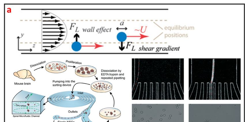
Micromachines 2019, 10, x FOR PEER REVIEW 9 of 31
cells against2019,
Micromachines a moving
10, 104 fluid. In recent years, Wu. et al., as shown in Figure 5b, reported a design9 and of 31
fabrication of a planar chip for high-throughput cell trapping and pairing by pDEP within only
several minutes [20]. The pDEP was generated by applying an alternating current signal on a novel
The pDEPinterdigitated
two-pair was generatedarray by applying
(TPIDA)anelectrode.
alternating Incurrent
Figuresignal on a novel
5c, Huang et al.two-pair
reportedinterdigitated
DEP-based
array (TPIDA) electrode. In Figure 5c, Huang et al. reported DEP-based single-cell
single-cell trap and rotation chip for 3D cell imaging and multiple biophysical property trap and rotation
chip for 3D cell[69].
measurements imaging
Theyand multiple
firstly biophysical
trapped property
a single-cell measurements
in constriction [69]. They firstly
and subsequently trapped
released it toa
single-cell in constriction and subsequently released it to a rotation chamber formed
a rotation chamber formed by four sidewall electrodes and one transparent bottom electrode, which by four sidewall
electrodes
are powered andbyone
ACtransparent
signals. bottom electrode, which are powered by AC signals.
Figure
Figure 5.5.Electrical
Electrical single-cell
single-cell manipulation
manipulation methodsmethods
and someand some
designs. designs.
(a) Theory (a) Theory of
of dielectrophoresis
dielectrophoresis
(DEP). Adapted by (DEP). Adapted
permission by Reference
from permission[68],
from Reference
copyright [68], copyright
Elsevier 2005. (b)Elsevier 2005. (b)
2D electrode 2D
to trap
electrode to trap
and pair single andAdapted
cells. pair single cells. Adapted
by permission frombyReference
permission
[20],from Reference
copyright Royal[20], copyright
Society Royal
of Chemistry
Society
2017. (c)of
3DChemistry
electrode to2017.
rotate(c) 3D cell.
single electrode to rotate
Adapted single cell.
by permission fromAdapted
Referenceby permission
[69], from
copyright Royal
Reference
Society of [69], copyright
Chemistry 2018.Royal Society electric
(d) Rotating of Chemistry 2018. (d) Rotating
field induced-charge electric fieldtoinduced-charge
Electro-osmosis trap single cell.
Electro-osmosis to trap single
Adapted by permission cell. Adapted
from Reference [70],by permission
copyright from Reference
American Chemical [70], copyright
Society 2016. American
Chemical Society 2016.
2.2.2. Electroosmosis
2.2.2.Electroosmotic
Electroosmosis flow is caused by the Coulomb force that is induced by an electric field on
net mobile electric flow
Electroosmotic charge in a solution.
is caused Two kinds
by the Coulomb of that
force electroosmosis
is induced by areanusually
electricused
field for cell
on net
manipulation,
mobile electricnamely,
chargealternating currentTwo
in a solution. electroosmosis
kinds of (ACEO), and induced
electroosmosis charge electroosmosis
are usually used for cell
manipulation, namely, alternating current electroosmosis (ACEO), andapplied
(ICEO). ACEO is induced by ionic cloud migration in response to a tangentially inducedelectric field
charge
on the electrode surface and only occurs when the applied frequency is far below
electroosmosis (ICEO). ACEO is induced by ionic cloud migration in response to a tangentially the charge relaxation
frequency
applied of thefield
electric fluid.
on ACEO is one surface
the electrode of the most
and promising
only occurselectrokinetic
when the appliedapproaches
frequencyfor is
developing
far below
fully integrated lab-on-a-chip systems because it is a label-free and well-established
the charge relaxation frequency of the fluid. ACEO is one of the most promising electrokinetic technique for
approaches for developing fully integrated lab-on-a-chip systems because it is a label-free and well-a
microelectrode fabrication, as well as low voltage requirement. Gilad Yossifon et al. reported
multifunctional microfluidic platform on-chip electroporation integrated with ACEO-assisted cell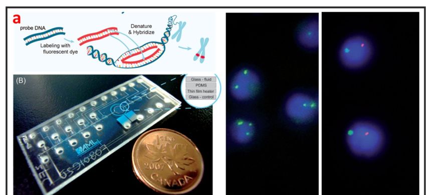
Micromachines 2019, 10, 104                                                                           10 of 31

trapping [71]. ACEO vortices enable the rapid trapping/alignment of particles at sufficiently low
activation frequencies. ICEO is an electrochemical effect that occurs on the surface of an object and
manifests as nonlinear fluid flow under electric conditions. As shown in Figure 5d, the induced charge
diffusion stimulated by the electric field induces slip-like local fluid flow under the applied electric
field. The induced diffusion charges are distributed in the boundary layer on the solid/liquid interface,
i.e., a double electrical layer. Electric force can be applied to the fluid molecules to control microfluidic
movement given the existence of the double layer [72]. ICEO efficiently enriches cells in specific
areas, and high-throughput and noncontact single-cell capture can also be achieved in a given area
(Figure 5d) [70]. The ICEO microfluidic chip can enable the small-scale integration of electrode arrays
and microchannels. The ICEO chip has a compact structure and is easy to process. Given that the
floating electrode does not require an external electrical signal wire connection, the design layout can
be flexibly designed in accordance with different application scenarios. However, the performance of
the ICEO microfluidic chip is dependent on the induced secondary flow. In the case of continuous
sampling, cell manipulation efficiency and precision will greatly decrease with the increase of the
flow rate.

2.3. Optical Method
    Three types of optical cell manipulation methods currently exist: Optical tweezer, optically
induced-dielectrophoresis (ODEP), and opto-thermocapillary.

2.3.1. Optical Tweezer
      The use of optical tweezers to move particles was first discovered by the American scientist Arthur
Ashkin. He found that a highly focused laser beam could drag an object with a higher refractive index
than the medium to the middle of the laser beam. He first studied the “optical tweezer” effect with a
single laser beam in 1987 [73]. The tweezer based on monochromatic lasers can manipulate particles
within the size range of nanometers to tens of microns. Therefore, the optical tweezer can be used
to manipulate biological single-cells. Robotic-assisted optical tweezers have enabled the automated
multidimensional manipulation of cells and have been applied in studies on cell mechanics [74],
cell transportation [42], and cell migration [75]. Optical tweezers can achieve cell manipulation
under static environments and combined with microfluidic chips to realize cell manipulation under
continuous flow. The most typical application is optical tweezer-enhanced microfluidic cell sorting [12].
As shown in Figure 6a, the cell sample is first focused on the channel upstream through the sheath
flow. Then, the cells are identified through the image processing of the fluorescence characteristics of
the cells. The tweezer automatically captures and drags the target single-cells to make them laterally
cross the streamline. The target single-cells are thus collected at a specific outlet.
      Optical tweezers offer the advantages of high accuracy, non-intrusiveness, and high-throughput
single-cell manipulation. However, the manipulative laser force exerted on the cells is typically
in the order of pico-Newtons. Thus, cell manipulation under continuous flow requires low fluid
velocity; otherwise, the optical tweezers will experience difficulty in deflecting cells. In addition,
the massive peripherical optical system required by this technique is difficult to miniaturize and is
also very expensive.
Micromachines 2019, 10, 104 11 of 31
Micromachines 2019, 10, x FOR PEER REVIEW 11 of 31
Optical single-cell
Figure 6. Optical single-cell manipulation
manipulation methods
methods and some designs. (a) (a) Optical
Optical tweezer
tweezer based
Adapted by permission
single-cell sorting. Adapted permission from
from Reference
Reference [12], copyright Royal Society
Society of
of Chemistry
Chemistry
2011. (b)
(b)ODEP
ODEPbased single-cell
based array
single-cell rotation.
array Adapted
rotation. by permission
Adapted from Reference
by permission [76], copyright
from Reference [76],
Royal Society of Chemistry 2017. (c) Opto-thermocapillary based single-cell pattern.
copyright Royal Society of Chemistry 2017. (c) Opto-thermocapillary based single-cell pattern. Adapted by
permission from Reference [77], copyright Royal Society of Chemistry 2013.
Adapted by permission from Reference [77], copyright Royal Society of Chemistry 2013.
2.3.2. Optically Induced Dielectrophoresis (ODEP)
2.3.2. Optically Induced Dielectrophoresis (ODEP)
Optically induced dielectrophoresis (ODEP) is a novel particle manipulation technology.
Optically induced dielectrophoresis (ODEP) is a novel particle manipulation technology. The
The forces used to manipulate particles in ODEP-based chip are the same as those used in traditional
forces used to manipulate particles in ODEP-based chip are the same as those used in traditional DEP
DEP technology. That is, a nonuniform electric field is used to polarize cells and generate DEP forces.
technology. That is, a nonuniform electric field is used to polarize cells and generate DEP forces. The
The difference between the two technologies lies in the technique by which the nonuniform electric
difference between the two technologies lies in the technique by which the nonuniform electric field
field is generated. In contrast to conventional DEP manipulation, ODEP does not need prefabricated
is generated. In contrast to conventional DEP manipulation, ODEP does not need prefabricated
electrode patterns. However, digital micromirror device (DMD) projector can be used to project the
electrode patterns. However, digital micromirror device (DMD) projector can be used to project the
light pattern onto the chip substrate via a microscope to generate flexible and controllable virtual
light pattern onto the chip substrate via a microscope to generate flexible and controllable virtual
electrodes [21]. Its working principle is similar to that of photovoltaic power generation. An amorphous
electrodes [21]. Its working principle is similar to that of photovoltaic power generation. An
silicon substrate material generates photocarriers under light excitation, thereby increasing carrier
amorphous silicon substrate material generates photocarriers under light excitation, thereby
concentration in the illumination area. Consequently, the electrical conductivity of the illumination
increasing carrier concentration in the illumination area. Consequently, the electrical conductivity of
area rapidly increases, thereby generating a nonuniform electric field. ODEP can also enable the
the illumination area rapidly increases, thereby generating a nonuniform electric field. ODEP can also
DEP manipulation of live single-cell. It is contactless and label-free. As shown in Figure 6b, Xie et al.
enable the DEP manipulation of live single-cell. It is contactless and label-free. As shown in Figure
utilized ODEP to effectively trap and transport unicellular swimming algae [76]. They found that the
6b, Xie et al. utilized ODEP to effectively trap and transport unicellular swimming algae [76]. They
trapped cells started to rotate and demonstrated that functional flagella played a decisive role in the
found that the trapped cells started to rotate and demonstrated that functional flagella played a
decisive role in the rotation. Furthermore, they also realized homodromous rotation of a live C.Micromachines 2019, 10, 104 12 of 31
rotation. Furthermore, they also realized homodromous rotation of a live C. reinhardtii cell array in an
ODEP trap and the speed of rotation can be controlled by varying the optical intensity.
The ODEP system is considerably simpler than optical tweezer systems and can be miniaturized.
Moreover, ODEP can manipulate cells that are not optically transparent, thus exhibiting great flexibility.
However, ODEP and its clinical applications are hindered by the same inherent drawbacks as
traditional DEP: The manipulation of cells in low-conductivity solutions. Moreover, the substrate of
the ODEP chip is opaque because of the deposition of amorphous silicon. The opacity of the substrate
precludes the use of an inverted biological microscope for live cell imaging.
2.3.3. Opto-Thermocapillary
Different from the above two optical methods, the opto-thermal method uses light to generate
heat for opto-thermophoresis or opto-thermocapillary. Thermophoresis is the thermos-migration or
thermos-diffusion of particles subjected to a temperature gradient [78]. The opto-thermophoresis
can be used to trap small biological molecules. However, it is difficult for trapping large particle,
such as cells. The thermocapillary, also named thermal Marangoni effect, refers to mass transfer
along a liquid–gas interface due to a surface tension gradient created by a temperature gradient.
Thus, opto-thermocapillary actuation is not dependent on the optical properties of the object.
And opto-thermocapillary is not sensitive to the electrical properties of the liquid medium and the
object. However, opto-thermocapillary actuation shares the flexibility of optical control, which enables
parallel and independent manipulation of multiple micro-objects [79]. Opto-thermocapillary force
can be used to actuate microbubbles that enable manipulating single-cells and biomolecules [80].
As shown in Figure 6c, a microbubble can be generated after focusing optical beam on the absorbing
coating. This microbubble can be seen as micro-scale actuator to manipulate single cell. Hu et al.
used a near-infrared laser focused on indium tin oxide (ITO) glass to generate thermocapillary effect
that can trap and transport living single cells with forces of up to 40 pN [77]. Moreover, they also
patterned single-cell in two kinds of hydrogels: Polyethylene glycol diacrylate (PEGDA) and agarose.
High viability rates were observed in both hydrogels, and single cells patterned in agarose spread and
migrated during culture.
2.4. Acoustic Method
Acoustic cell manipulation is based on the complex flow–structure interaction that occurs when
acoustic waves enter a microfluidic channel. Acoustic waves can be categorized into body and surface
waves. A surface acoustic wave (SAW) is an elastic acoustic wave that can propagate only on the
substrate surface. Most of its energy is concentrated on the substrate surface at a depth of several
wavelengths. Given their advantages of high frequency, high energy density, good penetrability,
and easy integration, SAW chips have been widely used in recent years for cell manipulation on
microfluidic chips. Interdigital transducers (IDTs) are generally used to generate SAW. The resonant
frequency of the SAW can be controlled by adjusting the interdigital spacing of electrodes. The resonant
frequency of SAW devices can reach up to GHz, indicating that they can precisely control micron-sized
or even submicron-sized particles. In addition, the distribution of the acoustic field can be regulated
by changing the shape of the IDTs, further demonstrating the flexibility of this manipulation method.
SAW devices are generally processed using standard microfabrication technology. Thus, SAW devices
have excellent reproducibility and consistency. The planar processing method enables the integration
of SAW devices into microfluidic chips. When acoustic waves propagate into a fluidic medium,
the fluid acquires momentum by absorbing acoustic waves. Bulk flow, in turn, is induced by acoustic
wave absorption. This phenomenon is called the acoustic flow effect. The particle moves with the
fluid if its size is substantially smaller than the wavelength and its density is small. This phenomenon
thus enables the manipulation of particles in the fluid. When two columns of SAWs propagate
opposite each other on the same surface, a standing surface acoustic wave (SSAW) is generated.
Under the influence of SSAW, particles are subjected to standing wave acoustic radiation force andMicromachines 2019, 10, x FOR PEER REVIEW 13 of 31
Acoustic radiation is mainly attributed to the effects of particles on sound waves. These effects
include reflection, refraction, and absorption and result in the exchange of momentum between
sound waves and particles. The magnitude of the acoustic radiation force is related to the physical
Micromachines 2019, 10, 104 13 of 31
properties, such as wavelength and amplitude, of the SSAW and the size and density of the particles.
In recent years, considerable research effort has been directed toward the establishment of SSAWs on
then accumulate
microfluidic chipsat the antinode
to realize or node
precise andposition depending on
high-throughput the properties
single-cell of the particles
manipulation. and the
As shown in
surrounding medium, such as density and compressibility. Acoustic radiation
Figure 7a, Collins et al. introduced multiple high-frequency SSAWs with one cell per acoustic well is mainly attributed
to the
for theeffects of particles
patterning on sound
of multiple waves. separated
spatially These effects include reflection,
single-cells [23]. They refraction, and absorption
also characterized and
and result in the
demonstrated exchange
patterning forofa wide
momentum
range of between
particlesound waves
sizes, and and particles.
patterning of cells,The magnitude
including human of
the acoustic radiation force is related to the physical properties, such
lymphocytes and red blood cells infected by the malarial parasite Plasmodium falciparum. as wavelength and amplitude,
of the SSAW and
Acoustic the size for
technology andsingle-cell
density ofmanipulation
the particles. presents
In recentthe years, considerable
advantages research
of high effort
frequency,
has been
high directed
energy density,toward
goodthe establishment
penetrability, easyof fabrication,
SSAWs on microfluidic chips and
easy integration, to realize precise and
noninvasiveness.
high-throughput
However, single-cell
the application ofmanipulation.
acoustic control Asinshown in Figure
microfluidic 7a, Collins
single-cell et al. introduced
manipulation multiple
remains in its
high-frequency
infancy and posesSSAWs with one
numerous cell perthat
problems acoustic well forresolution.
still require the patterning of problems
These multiple spatially separated
include nonlinear
single-cells [23].
interactions amongTheyacoustic
also characterized and demonstrated
waves, fluids, patterning
and cells. Moreover, for a wide
current range
acoustic of particle
chips sizes,
are mostly
and patterning
based on LiNbOof3 substrates,
cells, including
and human lymphocytes
device substrates basedandonrednew
blood cells infected
piezoelectric by the must
materials malarialbe
parasite Plasmodium falciparum.
investigated.
Figure 7. Acoustic,magnetic
7. Acoustic, magneticand
andmicrorobot
microrobot single-cell
single-cell manipulation
manipulation methods
methods andand some
some designs.
designs. (a)
(a) Surface
Surface acoustic
acoustic waves
waves based
based single-cell
single-cell pattern.Adapted
pattern. Adaptedbybypermission
permissionfrom
fromReference
Reference [23],
[23],
copyright Nature Publishing Group 2015. (b) Micromagnet based single-cell trap. Adapted by
permission from Reference [81], copyright Royal Society of Chemistry 2016. (c) Noncontact cell
transportation by oscillation of microrobot in microfluidic chip. Adapted by permission from
Reference [82], copyright AIP Publishing 2017.You can also read