Micro/Nanostructured Materials from Droplet Microfluidics - Wiley-VCH
←
→
Page content transcription
If your browser does not render page correctly, please read the page content below
1

1

Micro/Nanostructured Materials from Droplet Microfluidics
Xin Zhao 1 , Jieshou Li 1 , and Yuanjin Zhao 1,2
1 Medical School of Nanjing University, Research Institute of General Surgery, Jinling Hospital, No. 305,

East Zhongshan Road, Xuanwu District, Nanjing 210002, P. R. China
2
 Southeast University, State Key Laboratory of Bioelectronics, School of Biological Science and Medical
Engineering, No. 2, Sipailou, Xuanwu District, Nanjing 210096, P. R. China

1.1 Introduction
Since the emergence of microfluidics at the beginning of 1980s, microfluidic tech-
nologies have been extensively applied in the fabrication of materials with spe-
cific physicochemical features and versatile applications [1–3]. This relatively new
field is the synergy of science and technology of systems with integrated channels
on the microscale dimensions, through which small quantities of fluids (usually
10−9 to 10−18 l) can flow in designed configurations and are precisely controlled
and manipulated [4–6]. In the field of microfluidics, as fluid dimensions shrink
to the microscale level, their specific surface area increases, thus showing behav-
iors divergent from those of macroscopic fluids, which can be characterized by
three major phenomena: highly efficient mass–heat transfer, relative dominance
of viscous force over inertial force, and significant surface effects [7, 8]. In addi-
tion, the high integration of microfluidic channels facilitates the coexistence and
diverse interactions of multiple fluid phases and paves the way for miniaturized
systematic control over individual fluids and fluid interfaces [9, 10]. These fea-
tures offer obvious advantages over bulk synthesis, most notably in their ability to
ensure monodispersity and control the structure of final products [11–13]. There-
fore, microfluidics has promoted the development of multidisciplinary research
in physical, chemical, biological, medical, and engineering fields.
 Droplet microfluidics is an important subcategory of the microfluidic tech-
nologies, which generates and manipulates discrete droplets through immiscible
multiphase flows inside the microchannels [14–16]. In the past two decades,
fostered by great progress in both theoretical and technical aspects, droplet
microfluidics has fulfilled original expectations and become a significant
approach to generate materials for a broad range of applications [17–19]. The
basic principles and microfluidic devices for droplet generation are shown

Nanotechnology and Microfluidics, First Edition. Edited by Xingyu Jiang.
© 2020 Wiley-VCH Verlag GmbH & Co. KGaA. Published 2020 by Wiley-VCH Verlag GmbH & Co. KGaA.
2 1 Micro/Nanostructured Materials from Droplet Microfluidics

 in Figure 1.1, including a T-junction chip (Figure 1.1a), a flow-focusing chip
 (Figure 1.1b), and a coaxial structured chip (Figure 1.1c) [20]. In the T-junction
 chip, the dispersed phase flows from a vertical channel to a horizontal channel
 filled with the continuous phase. Under the combined action of both shear force
 and extrusion pressure from the continuous phase, monodispersed droplets
 are generated. In the flow-focusing chip, the dispersed phase flows from the
 middle channel and undergoes extrusion force of the continuous phase from all
 directions. The dispersed phase experiences stretching and breakage, leading to
 droplet formation. In the coaxial structured chip, the dispersed phase channel is
 embedded in the continuous phase channel, and the dispersed phase flows paral-
 lel to the continuous phase toward the same direction. Also, the dispersed phase
 is broken into droplets. In microfluidic systems, droplet generation is influenced
 by microchannel construction, viscosity and flow velocity of each phase, and
 interfacial tension between adjacent flows. Therefore, the dimensions and
 production rates of droplets can be regulated by adjusting the above parameters.
 In addition, through a flexible design of microchannels, double or even multiple
 emulsions could be generated in a controlled manner (Figure 1.1d,e) [21, 22].
 These microfluidic droplets have diverse morphologies and components and can
 serve as excellent templates to synthesize materials with specific structures and
 functions.
 With the development of microfabrication technology, considerable research
 has been made to synthesize microstructured materials (MMs)/nanostructured
 materials (NMs) because the microscopic architectures give additional prop-
 erties to the materials [23–26]. Conventional bulk methods usually adopt a
 certain physical or chemical procedure (e.g. mechanical stirring) [27, 28]. These
 methods usually generate materials with a monotonous morphology, and the
 dispersity of products and synthetic processes are difficult to control [29, 30]. In
 particular, for fabrication of composite materials, such as “intelligent materials”
 or “core–shell materials,” the conventional approaches are insufficient to meet
 the requirements. MMs/NMs synthesized from droplet microfluidics possess
 narrow size distribution, flexible structures, and desired properties [31–33].
 Compared to conventional methods, the advantages of microfluidic synthesis
 lie in the following aspects [20, 34–36]. The material size, structure, and compo-
 sition are easily controlled, resulting in superior properties and functions. The
 addition of reagents is very simple, which is beneficial for the manipulation of
 multistep and multireagent synthesis. Through scale integration of microfluidic
 systems and equipment automation, the complex reaction process can be largely
 simplified. Because majority of materials used to make microfluidic chip are
 facilitated to be observed, real-time monitoring of the reaction process could
 be realized, which helps to clarify the synthesis mechanism. Therefore, the
 application of droplet microfluidics to design and prepare MMs/NMs has
 become a hot topic recently and will bring about infinite possibilities for the
 future development of materials science.
 In this chapter, we summarize the classical and recent achievements in the
 MMs/NMs engineered from droplet microfluidics and their various applica-
 tions. We first provide an overview of MMs fabricated by droplet microfluidics,
 including the droplet formation mechanism and various microchips used to
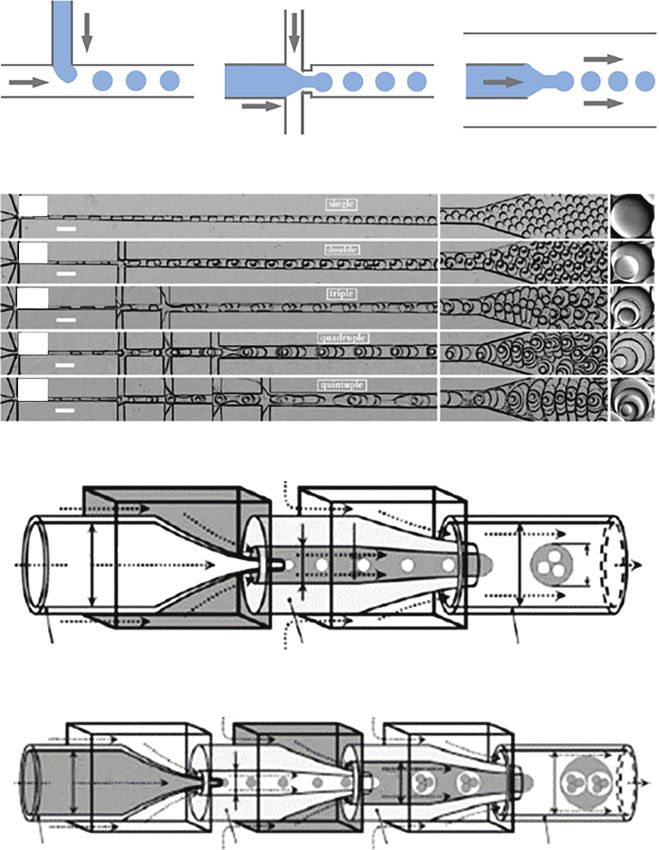
1.1 Introduction 3

(a) (b) (c)
 Dispersed Continuous Continuous phase
 phase phase

 Continuous phase Dispersed
 phase Dispersed phase

(d)
 (i)

 (ii)

 (iii)

 (iv)

 (v)

(e)
 Middle fluid Outer fluid (Q3)
 (Q2)
 D2

 d1

 Inner fluid
 D1

 D3

 d2
 (Q1)

 Injection tube Transition tube Collection tube

 Middle fluid (l) Middle fluid (lI) (Q3) Outer fluid (Q4)
 (Q2)
 D2

 Inner fluid
 D1

 D4
 D3

 (Q1)

 Injection tube Transition tube (I) Transition tube (II) Collection tube

Figure 1.1 (a–c) The principles and chip designs with different flow regimes for droplet
generation, including T-junction (a), flow-focusing (b), and coaxial (c) structured chip. Source:
Ma et al. 2017 [20]. https://www.mdpi.com/2072-666X/8/8/255. Licensed under CCBY 4.0 (d)
Generation of multiple emulsions in a stepwise flow-focusing device: (i–v) single-, double-,
triple-, quadruple-, and quintuple-emulsion droplets, respectively. Source: Adapted with
permission from Abate and Weitz [21]. Copyright 2009, John Wiley & Sons. (e) Generation of
multiple emulsions in a stepwise coflow platform. Source: Adapted with permission from Chu
et al. [22]. Copyright 2007, John Wiley & Sons.
4 1 Micro/Nanostructured Materials from Droplet Microfluidics

 generate different droplets, the methods to prepare MMs templated from
 these droplets, and the unique and complex structures enabled by microfluidic
 techniques. We then present basic synthesis methods for inorganic and organic
 NMs through droplet microfluidics, and the heterogeneous and multifunctional
 nanostructures from microfluidic platforms are also introduced. Following
 these two sections, much emphasis will be laid on the applications of the
 generated MMs/NMs, including drug delivery, cell encapsulation, TE, and
 analytical applications. Finally, we will discuss the current status and existing
 challenges and provide opinions on the directions of future development of
 droplet microfluidics in the synthesis of advanced MMs/NMs.

 1.2 MMs from Droplet Microfluidics
 Although the history of MMs with sizes ranging from 1 to 1000 μm has started in
 the 1960s, their application was only expanded recently after they were utilized
 as drug delivery agents by mimicking genetic materials carrying pollens [37–
 39]. Thereafter, other studies have continuously investigated the functionalities
 of MMs and they are now being utilized in various fields including pharmaceu-
 ticals, food industry, cosmetics, photonics, coatings, and printing [40, 41]. These
 applications of MMs depend on their properties that correlate with their size,
 structure, composition, and configuration [42, 43]. Typically, MMs have been
 prepared through traditional methods including emulsion polymerization, dis-
 persion polymerization, and spray drying [44]. These methods always result in
 MMs with large polydispersity, poor reproducibility, limited functionality, and
 less tunable morphology [44–46]. Therefore, it is becoming increasingly urgent
 to fabricate MMs with defined sizes, morphologies, and compartments in a con-
 trolled manner to improve their capability. Droplet microfluidics can generate
 emulsion droplets with a precisely controlled size, shape, and composition, which
 provide excellent templates for the synthesis of functional MMs with uniform
 size, controllable shape, and versatile compositions [47–49]. Moreover, precise
 control over single emulsion droplets by microfluidics allows further creation
 of multiple emulsions with highly controllable, nested, and droplet-in-droplet
 structures [50, 51]. Thus, using such multiple emulsions as templates, MMs with
 well-tailored internal compartments and specific functions can be successfully
 fabricated for many applications.

 1.2.1 Simple Spherical Microparticles (MPs)
 Simple spherical microparticles (MPs) are synthesized straightforwardly by
 solidification of the droplet templates, which involves a chemical or physical
 reaction process [52–54]. Photopolymerization is one of the most prevalent
 chemical processes because it enables in situ solidification and continuous
 fabrication in a fast response time, which helps to determine the particle
 location and better control the size distribution [55, 56]. For example, Jeong et al.
 developed a simple and cost-effective method for the fabrication of polymeric
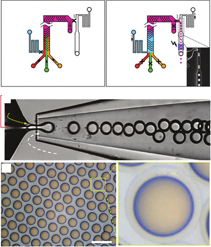
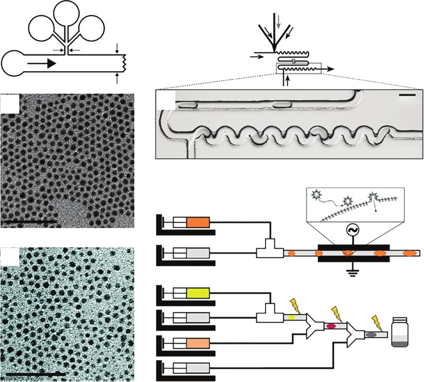
1.2 MMs from Droplet Microfluidics 5

MPs in droplet microfluidics [57]. The polymerizable sample fluid and the
immiscible nonpolymerizable sheath fluid (mineral oil) were introduced into
the inlet channels of the sample and sheath flow, respectively. Both fluids were
combined at the tip of the pulled micropipette (dotted area in Figure 1.2a),
producing hydrogel droplets floating among the sheath stream. The separated
droplets traveled through the main channel without touching the inner wall of
the channel and then the hydrogel droplets were polymerized by continuous
ultraviolet (UV) exposure at the unshielded area. The size of the MPs could
be adjusted within the range of tens to hundreds of micrometers by changing
the flow rates of the dispersed and continuous phases. This method has been
extensively applied for the synthesis of a large variety of MPs by using precursors
with unsaturated hydrocarbon chains.
 MPs synthesized via UV irradiation are inappropriate when considering
their biotoxicity and biocompatibility. In those cases, physical gelation or ionic
reactions are more applicable and has been employed to synthesize many kinds
of MPs [62, 63]. For example, Tan and Takeuchi described the production
of monodisperse alginate hydrogel MPs using a method that combined the
internal gelation method with T-junction droplet formation in microfluidic
devices (Figure 1.2b) [58]. They dispersed droplets of Na-alginate solution
containing CaCO3 nanoparticles (NPs) in a continuous phase of corn oil at room
temperature. Syringe pumps were used to infuse fluids into the microfluidic
device fabricated from polydimethylsiloxane (PDMS) using soft lithography
techniques. Corn oil with lecithin sheared off droplets of Na-alginate solution
containing insoluble CaCO3 NPs one at a time to generate an inverse emulsion
with a narrow size distribution. Lecithin was added to the corn oil to stabilize
the droplets against coalescence, thereby preserving the monodispersity of the
droplets. In downstream, acetic acid dissolved in corn oil was introduced and
mixed with oil flowing in the main stream. The acetic acid then diffused into
the aqueous Na-alginate droplets, reduced pH, and released Ca2+ ions from the
insoluble calcium complex, causing gelation. Also, they demonstrated that the
gelation conditions in this approach were mild enough to encapsulate cells
without loss of their viability.
 The low production rate of microfluidic devices for generation of MPs
has remained a key challenge to successfully translate many promising
laboratory-scale results to commercial-scale production of microfluidics-
generated materials [64, 65]. To address these challenges, Yadavali et al. incor-
porated an array of 10 260 (285 × 36) microfluidic droplet generators onto a
3D-etched single silicon wafer that was operated using only a single set of
inlets and outlets (Figure 1.2c) [59]. The monolithic construction from a single
silicon wafer obviated the alignment and bonding challenges of prior multilayer
approaches and allowed high-pressure use. To demonstrate the power of this
approach, they generated polycaprolactone solid MPs, with a coefficient of
variation (CV)
6 1 Micro/Nanostructured Materials from Droplet Microfluidics

 (a) UV (b) Corn oil with lecithin
 Corn oil with and acetic acid
 PDMS lecithin Mixing and reaction channel

 Sample flow
 Sodium T-junction
 Micropipette(glass) Alginate with
 CaCO3 Droplets
 nanoparticles undergoing
 Sheath flow gelation
 (Mineral oil)

 (c)

 (d) Janus droplets Aqueous phase Monomer
 (black)

 135° Monomer
 (white)
 200 μm Aqueous phase

 (e) (f)

 Alginate solution Alginate solution
 with red beads with green beads

 1 cm 500 μm

 Figure 1.2 (a) MP synthesis through UV-induced photopolymerization. Source: Adapted with
 permission from Jeong et al. [57]. Copyright 2005, American Chemical Society. (b) Synthesis of
 alginate MPs through the physical cross-linking process. Source: Adapted with permission
 from Tan and Takeuchi [58]. Copyright 2007, John Wiley & Sons. (c) Droplet generator design
 for high-throughput emulsion generation. Source: Yadavali et al. 2018 [59]. https://www
 .nature.com/articles/s41467-018-03515-2. Licensed under CCBY 4.0. (d) Formation of
 bicolored Janus droplets in a planar microfluidic geometry. Source: Adapted with permission
 from Nisisako et al. [60]. Copyright 2006, John Wiley & Sons. (e, f ) Photograph of the
 centrifugal microfluidic chip and fluorescence image of the Janus MPs. Source: Adapted with
 permission from Liu et al. [61]. Copyright 2016, Elsevier.
1.2 MMs from Droplet Microfluidics 7

arbitrary microfluidic droplet generators to be parallelized, it could produce
higher order emulsions and particles that required multistep processing.

1.2.2 Janus MPs
Janus particles, named after the ancient twofaced Roman god Janus, refer to parti-
cles with two hemispheres of different compositions. Such structural asymmetry
brings about combination of different features and functionalities. Janus particles
have received increasing attention because of their application values in various
areas [66, 67]. Janus droplets serve as templates for direct synthesis of Janus
particles through photoinduced or heat-induced polymerization, as well as
ionic cross-linking [68, 69]. For example, Nisisako et al. showed a microfluidic
technology to engineer monodisperse polymeric Janus particles with color
anisotropies (Figure 1.2d) [60]. First, pigments of carbon black and titanium
oxide were dispersed in an acrylic monomer (isobornyl acrylate, IBA) to prepare
separate black and white monomers. The black and white IBAs were introduced
into the Y-junction at the same volumetric flow rate to form a two-color stream.
In downstream, aqueous streams containing a steric stabilizer co-flow symmetri-
cally around the two-color stream. Droplets having black and white hemispheres
were formed reproducibly by a shear-rupturing mechanism at an appropriate
disperse-phase flow rate and continuous-phase flow rate. Then, monodisperse
bicolored particles were synthesized outside the fluidic module by thermal poly-
merization of the generated Janus droplets. The two-color boundary was obscure,
but these balls still had black and white hemispheres, with a CV less than 2%.
 Microfluidic generation of Janus MPs was mainly based on T-junction and
flow-focusing geometries. These particles were produced from the droplets
generated by the breakup of the fluid because of the Rayleigh–Plateau instability.
However, these methods depend strongly on the precise control over the
geometries of the chips and manipulation of the flow rate of each fluid [70, 71].
Recently, centrifugal microfluidics, taking advantage of centrifugal force for
particle generation, presented as an available method in manipulating the size
and structure of particles and exhibited potentials in preparing particles with
complex structures [72]. Liu et al. synthesized Janus MPs based on droplet tem-
plates formed by using a centrifugal microfluidic technique [61]. The centrifugal
system simply consisted of a spin coater and a chip fabricated using the universal
soft-lithographic technique (Figure 1.2e). By designing two channels adjacently
parallel with each other, Janus alginate particles with two distinct fluorescent
hemispheres could be synthesized (Figure 1.2f ). In addition, the production
throughput of the particles could be dramatically increased simply by arranging
plenty of parallel channels on the chip.

1.2.3 Core–Shell MPs
Core–shell MPs are microscale materials composed of solid, liquid, or gas
bubbles surrounded by a shell or coating. Because of the unique core–shell
structure and high flexibility of material selection, these MPs could be imparted
with diverse properties and functionalities such as efficient encapsulation,
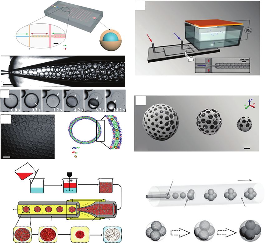
8 1 Micro/Nanostructured Materials from Droplet Microfluidics

 controlled release, mass transfer, mechanical response, etc. [73, 74] In conven-
 tional approaches such as shear-induced sequential emulsification, core–shell
 MPs are fabricated with polydispersity in size and shape, which are unfavorable
 for practical applications [75]. Droplet microfluidics overcomes this dilemma
 because of its ability to fabricate uniform emulsion droplets with a precisely
 controlled size and morphology. In a single-emulsion system, core–shell MPs
 could be derived through phase separation, wettability control, interfacial reac-
 tion, and assembly [76, 77]. Also, core–shell MPs could be conveniently derived
 from multiple emulsion templates via different shell solidification processes
 such as triggered polymerization, solvent evaporation, phase transition, and
 dewetting [78, 79]. For example, Montazeri et al. used a flow focusing system
 to create core–shell MPs [80]. The microfluidic device consisted of three inlets
 and one outlet was made by soft lithography. In the first flow focusing part,
 the H2 O2 solution as a disperse phase was introduced into the central channel.
 The poly(lactic-co-glycolic acid) (PLGA) solution entered from the second
 inlet and flowed into the two side channels as the continuous phase. At the
 junction, the PLGA solution stream splits the H2 O2 stream, which resulted in
 the formation of H2 O2 droplets. This emulsion encountered the second flow
 focusing part while it flowed in the central channel. At the junction, the emulsion
 was dispersed by a poly(vinyl alcohol) (PVA) solution as the second continuous
 phase, which led to the generation of a double emulsion. After extracting the
 solvent, core–shell structured, uniform PLGA MPs were successfully fabricated
 (Figure 1.3a).
 To enhance the practical performances, more complex MPs with core–shell
 structure have been fabricated [85]. Through stepwise emulsification, dou-
 ble and higher order polymersomes were generated, with a shell membrane
 being added in each step. Ingredients encapsulated in different levels could
 be released in a programmed manner by sequentially rupturing the multilayer
 membranes [86]. For example, Amstad et al. used capillary microfluidic devices
 to produce monodisperse W/O/W double-emulsion drops as templates to
 form polymersomes (Figure 1.3b–d) [81]. The device consisted of two tapered
 cylindrical capillaries inserted in one square capillary. An aqueous solution of
 poly(ethylene glycol) (PEG) was injected as the innermost phase. A mixture
 of chloroform and hexane containing PEG-b-poly(lactic acid) (PLA) diblock
 copolymers was injected as the middle oil phase. To render the membranes
 thermoresponsive feature, poly(N-isopropylacrylamide) (PNIPAM)-b-PLGA
 diblock copolymers were added, and to render the membrane photoresponsive
 feature, dodecylthiol-stabilized gold nanoparticles (AuNPs) were added into the
 oil phase. An aqueous solution of PVA was injected as the outer continuous
 phase. The resulting double-emulsion drops were flowed through the collection
 capillary and collected. After the diffusion-induced dewetting process, the two
 amphiphiles assembled into polymersomes with AuNPs located in the bilayers
 (Figure 1.3e). The resultant polymersomes thus showed a thermoresponsive
 release behavior when the temperature was raised above the lower critical
 solution temperature of the PNIPAm-b-PLGA copolymer. Additionally, because
 of the photothermal feature of AuNPs, the polymersomes were endowed with a
 photoresponsive feature and encapsulant release capacity.
1.2 MMs from Droplet Microfluidics 9

 (a) (g)

 Alginate
 solution Cyclohexane
 CaCl3

 FC-40

 (b)

 (c)
 (h)

 (d) (e)

 μCT 150 μm
 PEG-b-PLA
 PNIPAM-b-PLGA
 Dodecylthiol-stabilized Au NPs

 (f)
 (i) Go sloution Flow direction

 SiO2-dispersed ETPTA t
 Water with surfactan

 Polymerization Reduction

Figure 1.3 (a) Schematic presentation of the partially hydrophobic/hydrophilic chip for
fabrication of the core–shell-structured MPs. Source: Adapted with permission from Montazeri
et al. [80]. Copyright 2016, Royal Society of Chemistry. (b–e) Optical microscopy image
showing the generation of double-emulsion drops in a capillary microfluidic device (b); a
series of optical microscopy images showing dewetting of the middle phase on the surface of
the innermost drop, leading to the formation of polymersomes (c); optical microscopy image
of monodisperse polymersomes (scale bar = 200 mm) (d); and schematic illustration of the
polymersomes (e). Source: Adapted with permission from Amstad et al. [81]. Copyright 2012,
John Wiley & Sons. (f ) Schematic illustration of the preparation procedure of open-celled
porous PNIPAM microgels. Source: Adapted with permission from Mou et al. [82]. Copyright
2014, American Chemical Society. (g, h) Schematics of the device used for the manufacturing
of porous microbeads (g); 3D reconstructions of the porous microbeads (h). Source: Adapted
with permission from Costantini et al. [83]. Copyright 2018, John Wiley & Sons. (i) Schematic
diagram of the capillary microfluidic device used to generate the W/O/W double and the
fabrication process of the porous particles encapsulated with spongy graphene. Source:
Adapted with permission from Wang et al. [84]. Copyright 2015, John Wiley & Sons.

1.2.4 Porous MPs
Porous particles are valuable because of their distinct structure and applicable for
drug delivery, adsorption, sensors, etc. [87] By using droplet microfluidic tech-
niques, porous particles could be synthesized by introducing templates into the
droplet precursors and then removing them after solidification, thus generating
void spaces in the particles [88]. For example, Mou et al. synthesized open-cell
10 1 Micro/Nanostructured Materials from Droplet Microfluidics

 porous PNIPAM microgel particles by using tiny oil drops as porogens [82].
 The oil drops were first embedded in the aqueous phase of NIPAM monomers.
 Such a mixture was then emulsified to produce W/O emulsion droplets, which
 were polymerized upon UV irradiation. Afterward, by adding 2-propanol or
 by increasing the temperature, the embedded oil drops were squeezed out in
 response to volume shrinkage of the PNIPAM microgel. The resultant microgel
 particles were accommodated with a large number of interconnected free
 channels and thus showed enhanced thermal response rates compared with
 normal hydrogels (Figure 1.3f ).
 Apart from using single droplets as templates, double emulsions with multiple
 encapsulated inner droplets can also be used as templates for the fabrication of
 the porous MPs. Costantini et al. fabricated highly tailorable porous MPs by cou-
 pling a microfluidic droplet generator with a secondary breakup triggered by a
 pulsed electric field (EF) (Figure 1.3g) [83]. The method started with the genera-
 tion of a monodisperse O/W emulsion inside a flow-focusing microfluidic device.
 This emulsion was later broken-up, with the use of EF, into mesoscopic double
 droplets, which in turn served as a template for the porous MPs (Figure 1.3h).
 The porosity and the pore size could be controlled independently by regulating
 the flow rates of the two immiscible phases. Further, they showed that the overall
 size of microbeads could be precisely controlled in a wide range by using electro-
 dripping with a pulsed EF applied to the exit needle of the microfluidic device.
 By using short EF pulses with adjustable amplitude and frequency, they were able
 to avoid electrocoalescence of the inner droplet phase and further fine-tune the
 double-emulsion drop sizes. Because of its high reproducibility, high flexibility
 in terms of achievable particle morphologies, and potential versatility in terms of
 processable biomaterials, this coupled method advanced the current state of the
 art of porous MP synthesis.
 Recently, Wang et al. generated porous MP adsorbents encapsulated with
 spongy graphene oxide (GO) by a coaxial capillary microfluidic device composed
 of inner, middle, and outer capillaries (Figure 1.3i) [84]. The GO solution, silica
 NPs dispersed in ethoxylated trimethylolpropane triacrylate (ETPTA), and an
 aqueous surfactant solution were used as the inner, middle, and outer phases,
 respectively, and were forced to flow through the corresponding capillaries.
 When these fluids flowed through the capillaries, GO aqueous core droplets
 were generated at the end of the inner capillary and subsequently encapsulated
 by a shell drop of the ETPTA at the end of the middle capillary in dripping mode.
 The overall size and the numbers of the encapsulated core droplets of the double
 emulsions could be adjusted by tuning the orifice size of the capillaries and
 the velocities of the three phases. Under UV illumination, the openings of the
 encapsulated cores to the particle surface were formed because of mechanical
 damages to the ultrathin and fragile shell layers during the treatment. Such
 porous spongy structure, together with the encapsulated GO, imparted the MPs
 with the ability of adsorbing oils both floating on and under water.

 1.2.5 Other MMs
 MMs with other shapes also show unique properties and have specific applica-
 tions [89, 90]. For example, cylindrical MMs self-assembled from copolymers can
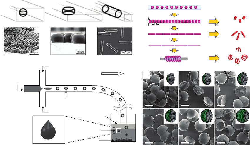
1.2 MMs from Droplet Microfluidics 11

persist in the blood circulation of rodents 10 times longer than their spherical
counterparts. Helical MMs can convert rotational motion into translational
motion in liquid media under remote control of a rotated magnetic field, showing
great potentials for many applications [91]. Thus, creation of uniform MMs
with versatile shapes is crucial for achieving advanced functions. With excellent
manipulation of microflows, droplet microfluidics provides a powerful platform
for fabricating MMs with versatile structures and compositions. One of the most
convenient approaches is to exert spatial confinement. Xu et al. described a
versatile strategy of synthesizing tripropyleneglycol diacrylate (TPGDA) MMs in
various shapes such as spheres, disks, and rods, by controlling the droplet diame-
ter and cross-sectional geometry (height and width, h and w, respectively) of the
microfluidic channel [92]. As shown in Figure 1.4A, when both of the geometries
were smaller than ds, the droplet maintained its original spherical shape, when
w > ds and h < ds, that is, the droplet flowed into a wide channel, it changed to
a disk shape, and when both of the geometries were smaller than ds, the droplet
was confined into a rod-like shape. By illumination with UV light, these droplets
were polymerized into solid particles and their shapes were retained. Another
facile approach was introduced by Wang et al.; they encapsulated monodisperse
droplets generated from microfluidics into cross-linked polymeric networks via
interfacial cross-linking reaction in microchannel to produce droplet-containing
fiber-like matrices [93]. By stretching and twining the dried fiber-like matrices,
the encapsulated droplets could be engineered into versatile shapes from tablet
to helix. Based on these deformed droplet templates, versatile MMs were
synthesized, such as tablet-like, rod-like, needle-like MMs and complex 3D
helices for magnetic-driven rotational and translational motion (Figure 1.4B).
 The material shape can also be tailored by controlling the reaction parameters
during the solidification process. For example, Lin et al. synthesized tail-shaped
alginate MPs in a slow cross-linking process. As shown in Figure 1.4C, sodium
alginate droplets were first generated in a microfluidic device and then fell
from the oil carrier phase into a CaCl2 solution under gravity [94]. During the
slow sedimentation process, the droplets were deformed under the competitive
effects of viscous deformation and the interfacial restoring forces, which resulted
in the generation of alginate MPs with teardrop or tail shapes. By changing
the alginate viscosity and the Ca2+ concentration, the size and the morphology
of the particles could be tuned. In another interesting study, acorn-like or
sharp-edged MMs were fabricated by tuning the wettability properties between
two immiscible drops. When the drop pairs were emulsified together in a third
carrier fluid phase and came into contact, an equilibrium structure formed
in accordance with the spreading coefficient values and droplet volumes. By
carefully controlling the interfacial tensions between the two fluid phases
using surfactants, the spreading coefficients could be adjusted so that partial
engulfment between the two dispersed phases occurred in compliance with the
minimum total interfacial energy. Therefore, the drop pairs could finally form
a dumbbell- or acorn-shaped configuration. Additionally, Nisisako and Torii
synthesized particles with sharp edges by selective polymerization of one of
the droplet pairs. They constructed a triphase microfluidic system composed
of photocurable monomer 1,6-hexanediol diacrylate (HDDA), a silicone oil
phase, and an aqueous phase [95]. Biphasic droplets were generated downstream
(A) (B) Droplet-containing fiber-like matrix Microstructured
 materials
 Template
 Drying synthesis

 D
 L
 Stretching

 Stretching

 Twining

 (C) Continuous phase: oil
 Dispersed phase: (a) (b) (c)
 1% Na-alginate (D)
 Flow direction
 in water

 Na-alginate emulsion

 (d) (e) (f)
 Continuous phase: oil Oil

 Ca-alginate
 particle
 CaCl2

Figure 1.4 (A) Representations of the shapes of droplets in the microfluidic channel, and optical microscopy images of microfluidic MMs based on these
deformed droplets. Source: Adapted with permission from Xu et al. [92]. Copyright 2005, John Wiley & Sons. (B) Manipulation of the encapsulated droplets by
drying, stretching, stretching, and twining for flexible deformation and synthesis of nonspherical MMs and helices from the deformed droplets. Source:
Adapted with permission from Wang et al. [93]. Copyright 2017, John Wiley & Sons. (C) Formation of a tail-shaped Ca-alginate particle from a spherical
Na-alginate droplet. Source: Adapted with permission from Lin et al. [94]. Copyright 2013, John Wiley & Sons. (D) MMs of various shapes engineered from
Janus droplets containing different volume ratios of silicone oil and the monomer. The scale bars represent 100 μm. Source: Adapted with permission from
Nisisako and Torii [95]. Copyright 2007, John Wiley & Sons.
1.3 NMs from Droplet Microfluidics 13

at equilibrium, and MPs were synthesized by photopolymerization of the
monomer. It was demonstrated that, with increasing fraction of the HDDA
monomer, the particle shape varied from convex to planar and further became
concave (Figure 1.4D).

1.3 NMs from Droplet Microfluidics
In recent decades, NMs have drawn significant attention in various applications
[96, 97]. Because of electric confinement and surface asymmetry effects, NMs
show distinct properties such as optical emission in semiconductor NMs and
surface plasmon resonance in noble metal NMs. Additionally, as their dimen-
sion is similar to that of biomolecules, they can be tailored to coordinate with
biological systems and showed unique properties in imaging, optoelectronics,
catalysis, sensing, and drug delivery [98, 99]. The synthesis of NMs goes through
four steps: supersaturation, nucleation, growth, and aggregation, and there have
emerged many techniques for NM synthesis, which can be classified into two
main categories: “top-down” and “bottom-up.” [100] Although the properties of
NMs are highly related to their size and morphology, it is technically challenging
in conventional batch processes to reproducibly fabricate NMs having a desired
morphology with a small standard deviation [101].
 Since 1990s, much research effort has been devoted to the synthesis of NMs by
droplet microfluidics. In contrast to conventional batch systems, the microflu-
idic method stands out for its intrinsic advantages, including miniaturization,
enhanced mass and heat transfer, and reduced time and reagent consumption.
Especially, the droplet reactor offers additional fascinating strengths. For
example, as the reaction is confined in the microscale droplets, toxic or volatile
chemicals can be utilized, and the resultant NMs would not contact the channel
walls, thus avoiding possible contamination and blocking. In addition, the
advection flow field within the droplets further improves the mixing efficiency,
thus offering a well-defined starting point and a consistent residence time, which
contributes to a narrower size distribution of the final NMs. Moreover, local
control over the synthetic environments could be exerted on separate droplet
reactors. Therefore, the reaction parameters scale up linearly, enabling homoge-
neous synthesis and quantity production [102–105]. Here, we reviewed recent
developments in synthesizing inorganic, organic, and other composite NMs
through droplet microfluidics.

1.3.1 Inorganic NMs
Inorganic NMs can be classified as amorphous and crystalline ones. Their
chemical and physical properties are related to the size, shape, and structure of
the particles. Thus, the monodispersity of inorganic NMs should be considered
during the formation process, which is largely dependent on the specially
controlled reaction kinetics, rapid mixing of the injected precursors, and
well-defined time–temperature profiles [106, 107]. All of these parameters
14 1 Micro/Nanostructured Materials from Droplet Microfluidics

 can be precisely regulated in microfluidics based on microscale characteristics
 [108, 109]. Controllable synthesis of colloidal semiconductor, metal, metal
 oxide, and hybrid NMs has been demonstrated. For example, Lazarus et al.
 used a two-phase microfluidic droplet device to synthesize AuNPs and silver
 nanoparticles (AgNPs) [110]. As shown in Figure 1.5a, a carrier oil phase was
 injected through inlet 1. The two reaction reagents of a metal salt precursor
 and the reductant flowed via inlets 2 and 4, respectively. Also, an ionic liquid
 stream flowed through inlet 3 and served as a stabilizer and also prevented
 contact of the reaction reagents before droplet formation. When droplets were
 generated in the T-junction and kept in the dripping regime, the recirculating
 streamline induced a convective flow, which largely accelerated mixing of the
 two reaction reagents. This promoted a rapid nucleation burst and thus ensured
 a homogeneous synthesis environment. As demonstrated by the authors in
 Figure 1.5b,c, well-dispersed spherical NPs were obtained that were smaller
 and more monodisperse than those produced in analogous batch reactions as a
 result of the rapid mixing and the homogeneous reaction environment afforded
 by the discrete droplets within an immiscible carrier phase.
 Besides the demands for homogeneity in NMs, controllable nanostructures are
 another significant consideration. Based on the flexible design of microfluidic
 chips and flows, various complex nanostructures have been achieved, such as
 core–shell NPs, nanogels with controlled pore size, Janus NPs, and other com-
 plex materials [100–102]. Shestopalov et al. reported a plug-based, microfluidic
 method for performing multistep chemical reactions to synthesize CdS/CdSe
 core–shell NPs with millisecond time control [111]. In this microfluidic method,
 the investigators first generated droplets from the initial reaction mixture. Two
 aqueous reagent streams were brought together into the channel where they were
 allowed to flow laminar alongside each other (labeled R1 and R2 in Figure 1.5d).
 These reagent streams were then sheared into droplets by an inert stream (labeled
 S in Figure 1.5d). The winding channels induced mixing by chaotic advection,
 and the droplets were allowed to react rapidly. To initiate the second stage of
 the multistep reaction, an aqueous stream of an additional reagent (labeled R3
 in Figure 1.5d) was directly injected into the droplets at a junction. The sec-
 ond reaction proceeded as droplets flowed through another length of serpentine
 channel (Figure 1.5e). Therefore, by conducting multistep reactions in droplets,
 the CdS/CdSe core–shell NPs were produced and prevented from aggregating on
 the walls of the microchannels.
 Because of the small dimensions of droplets and the closed environment of
 a pressure-driven flow system, it is typically difficult to control the delivery of
 chemicals across the continuous phase into the microdroplets. As a result, most
 applications involve only an initial mixing of all the chemicals prior to the gener-
 ation of microdroplets. However, many chemical reaction systems require addi-
 tion of chemicals into generated microdroplets at precise time intervals [113,
 114]. An effective method is to directly inject chemicals into the droplets through
 a side channel, where the chemical solution forms a pendant drop at the junc-
 tion and merges with the microdroplets passing by. Based on previous studies,
 Gu et al. presented a novel method that could control material transport into
 the microfluidic droplets [112]. Instead of using an inert oil as the carrier fluid,
1.3 NMs from Droplet Microfluidics 15

(a) (d) S
 3
 R1 R2
 2 4
 1000 μm
 200 μm Oil
 1 Out

 R3
 (e) 100 μm
(b)

 wf = 0.2, U = 67 mm s–1

 (f) Nanodroplet

 Aqueous DP Convection
 Electrocoalescence

(c)
 W/O miniemulsion CP
 HAuCI4/PVP
 solution

 Ascorbic acid
 emulsion
 Na2PdCI4
 emulsion
 Au-Pd core–shell
 Ascorbic acid nanoparticles
 emulsion

Figure 1.5 (a–c) Schematic representation of the multiple inlet T-junction microfluidic device
used to synthesize AuNPs and AgNPs (a); transmission electron microscopy micrographs of
AuNPs (b) and AgNPs (c) produced in a droplet-based microfluidic device. Scale bars were
50 nm. Source: Adapted with permission from Lazarus et al. [110]. Copyright 2012, American
Chemical Society. (d, e) A schematic diagram of the microfluidic network (d) and a micrograph
showing droplets merging with the aqueous stream (e). Source: Adapted with permission
from Shestopalov et al. [111]. Copyright 2004, Royal Society of Chemistry. (f ) Experimental
setup for generating aqueous microdroplets and Au-Pd core–shell NPs with a W/O
miniemulsion and electrocoalescence. Source: Gu et al. 2018 [112]. https://pubs.rsc.org/en/
content/articlelanding/2018/lc/c8lc00114f#!divAbstract. Licensed under CCBY 3.0.

a W/O miniemulsion was used by the investigators as the continuous phase to
generate aqueous monodisperse microdroplets as dispersed phase (Figure 1.5f ).
The W/O miniemulsion was a thermodynamically metastable system, composed
of 50–500 nm aqueous nanodroplets dispersed in an immiscible organic solvent
with a stabilizing surfactant. Via electrocoalescence, these nanodroplets served as
carriers for chemicals and were transported into the microdroplets. As the nan-
odroplets were 3 orders of magnitude smaller than the microdroplets, the inves-
tigators could easily achieve a nanodroplet-to-microdroplet population ratio of
greater than 1 million. Such a large population ratio made it possible to con-
trol the chemical addition rate over a wide range, and the addition was in fact
“quasi-continuous.” Finally, this method was successfully applied to a single-step
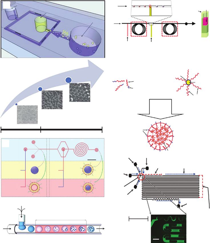
16 1 Micro/Nanostructured Materials from Droplet Microfluidics

 synthesis of AuNPs and a multistep flow synthesis of Au-Pd core–shell NPs with
 a narrow size distribution.

 1.3.2 Organic NMs
 Amphiphilic molecules such as block copolymers and lipids can self-assemble
 into NPs when they experience a change in solvent quality. A common and flexi-
 ble way to accomplish such a change is by mixing the solvent with the antisolvent,
 where the mixing time directly influences the final size and size distribution of
 the resultant NPs [115, 116]. However, the heterogeneous environment prevents
 stabilization of the nascent NPs, facilitates their aggregation, and leads to for-
 mation of larger and polydisperse products. In microfluidic systems, the highly
 efficient mixing of the flow has resulted in polymeric and lipid NPs with tunable
 size, narrow distribution, and batch-to-batch reproducibility [117, 118]. For
 example, Hung et al. presented droplet microfluidics-based solvent evaporation
 and extraction process to enable the controlled generation of monodisperse
 PLGA particles (Figure 1.6a,b) [119]. A mixture of PLGA-DMSO and water
 droplets was formed in a carrier phase of silicon oil. After droplet coalescence,
 DMSO was extracted out into water, and the PLGA nanospheres precipitated
 as a result of supersaturation. By tuning the PLGA concentration in solvent and
 the relative flow rates of oil and aqueous phases in the system, they were able to
 synthesize particles ranging from 70 nm to 30 μm in diameter.
 Although the size-controlled synthesis of polymeric NPs was achieved by the
 aforementioned one-stage microfluidic chips, it is still difficult to synthesize the
 hybrid core–shell NPs with tunable sizes because of their complex structures.
 Recently, via a specifically designed two-stage microfluidic chip, Zhang et al.
 realized the synthesis of controllable core–shell NPs with polymer cores and
 lipid shells. The first stage of the chip consisted of three inlets and one straight
 synthesis channel, whereas the second stage had one middle inlet and a spiral
 synthesis channel (Figure 1.6c) [104]. In mode A, they introduced PLGA solution
 into the first stage of chip to precipitate intermediate PLGA NPs and injected
 lipid solution into the second stage to assemble lipid monolayer shell onto
 the surface of PLGA NPs by hydrophobic attraction between lipid tail and
 PLGA. In mode B, they generated an intermediate liposome by injecting lipid
 solution into the first stage, which could reassemble onto the PLGA NPs when
 PLGA solution was injected into the second stage. In mode A, the NPs were
 covered by lipid–monolayer–shell, whereas in mode B, NPs were coated by
 lipid–bilayer–shell. The results indicated an enhanced mixing effect at the high
 flow rate in microfluidic chips, thus resulting in the assembly of small and
 monodisperse hybrid NPs.

 1.3.3 Other NMs
 Metal–organic frameworks (MOFs) are porous crystalline materials consist-
 ing of metal clusters or ions that act as connecting nodes and rigid organic
 bridging ligands. They have attracted immense attention because of their
 potential for extremely diverse structural topologies and tunable chemical
1.3 NMs from Droplet Microfluidics 17

 (a) 1% PVA (e) me
 rgin
 g
 Co3BTC2
 Continuous phase Co3BTC2 Ni3BTC2 (core)
 PLGA/DMC crystals (shell)
 Discrete phase in droplets

 PLGA particles
 So
 eva lvent Mineral
 por BPR
 atio oil
 n

 140 °C 140 °C, 4.5 MPa
 Co3BTC2@Ni3BTC2
 Core MOF Shell MOF
 precursor precursor

 (b) (f)
 PS-b-PAA block copolymer PS-CdS quantum dot building block
 stabilizing chains
 PACd layer

 PS block CdS quantum
 dot
 PAA block

 PS corona

 Water
 addition

 Quantum dot compound
 micelle
 PAA
 10 nm 1 μm 30 μm

 Stage Second stage
 (c) Inlet 1 Inlet 2 Outlet

 PS-CdS
 5 mm
 DMF/water inlet Argon inlet

 MP DMF Mixing channel Flow direction
 Mode A: PLGA Lipid separator
 inlet

 BP
 Mode B: Lipid PLGA
 Injector

 DMF/solids inlet

(d) Organic
 Solvents
 Metallic
 Outlet
 ligand salt
 Post formation
 Reaction 1 cm channel
 time

Oil

 Droplet Solvothermal
 generation synthesis

Figure 1.6 (a, b) Schematic of device design for the solvent evaporation method (a) and size
graph showing that a wide range of particle sizes were achieved with the extraction and
evaporation methods (b). Source: Adapted with permission from Hung et al. [119]. Copyright
2010, Royal Society of Chemistry. (c) Schematic of the two-stage microfluidic chip and
generated monolayer-covered or bilayer-covered PLGA NPs. Source: Adapted with permission
from Zhang et al. [104]. Copyright 2015, American Chemical Society. (d, e) Schematic
representation of the general microchemical process (d) and the integrated hydrothermal
microchemical process for synthesis of core–shell MOFs (e). Source: Adapted with permission
from Faustini et al. [120]. Copyright 2013, American Chemical Society. (f ) Schematic of the
QDCM assembly process and the microfluidic reactor. Source: Adapted with permission from
Wang et al. [121]. Copyright 2010, American Chemical Society.

functionalities [122, 123]. Microfluidics has recently been employed for the
synthesis of MOFs. For example, Faustini et al. reported an ultrafast and
continuous synthesis of versatile MOFs with unique morphologies based on
microfluidic strategy. Compared to conventional batch processes, the reaction
kinetics of MOFs preparation were tremendously improved in confined droplets
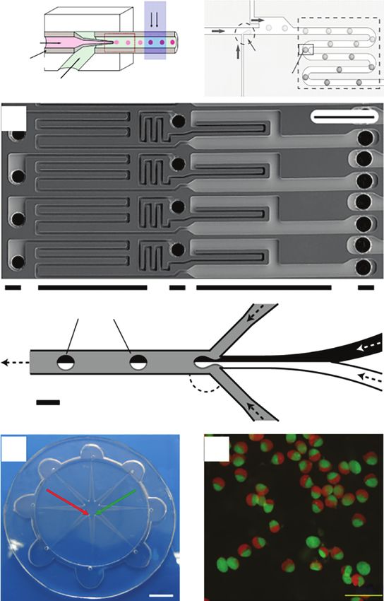
18 1 Micro/Nanostructured Materials from Droplet Microfluidics

 (Figure 1.6d) [120]. Representative MOF structures, such as HKUST-1, MOF-5,
 IRMOF-3, and UiO-66, were synthesized within a few minutes. In addition,
 three different types of core–shell MOFs composites, i.e. Co3 BTC2 @Ni3 BTC2 ,
 MOF-5@diCH3 -MOF-5, and Fe3 O4 @ZIF-8, were synthesized by exploiting a
 unique two-step integrated microfluidic system (Figure 1.6e). Unique features
 such as anisotropic crystal growth or enhanced stability against moisture were
 observed in these MOFs. Therefore, the microfluidic strategy allowed continuous
 fabrication of high-quality MOFs crystals and composites exhibiting distinct
 morphological characteristics in a time-efficient manner.
 The droplet platform also provides a microchamber for NM assembly into
 high-order structures, which exhibit distinct features and potential application
 values. Wang et al. used a two-phase gas–liquid-segmented microfluidic reactor
 to control the self-assembly of polystyrene-coated quantum dots (PS-CdS) and
 stabilizing PS-b-PAA block copolymer into quantum dot compound micelles
 (QDCMs) (Figure 1.6f ) [121]. Mixing of water with polymeric constituents
 was greatly enhanced because of chaotic advection in the liquid plugs as they
 traveled through the sinusoidal channel. In addition, circulating flow within the
 liquid plugs provided two convenient handles for size control following initial
 self-assembly: shear-induced particle breakup and collision-induced particle
 coalescence. The resulting particle size was a balance of the relative rates of
 these fluids under a specific set of experimental parameters. By changing the
 self-assembly conditions, the mean particle size was tuned in the range of
 40–137 nm. These results demonstrate that microfluidic strategies have obvious
 advantages in controlling self-assembly of block copolymers and other colloids.

 1.4 Applications of the Droplet-Derived Materials
 Droplet microfluidics enables synthesis of materials with uniform and highly con-
 trolled sizes and structures. By incorporating specific ingredients, such materials
 could be endowed with distinct physical and chemical properties such as opti-
 cal features, mechanical strength, selective permeability, and stimulus-responsive
 capacity. Therefore, they are highly applied in various fields. Herein, we categorize
 their applications into several aspects.

 1.4.1 Drug Delivery
 Encapsulation and controlled release of active agents are of significant interest in
 developing advanced delivery system for drugs, nutrients, fragrances, and cos-
 metics. Especially, for efficient drug delivery, the agents should be encapsulated
 within carriers with desired doses and then released in a specific target location
 [124, 125]. However, the clinical translation of drug delivery systems is relatively
 slow, which can be partially ascribed to the poor control of the preparation
 processes in the conventional batch method [126]. For example, the poly-
 meric particles prepared by the conventional batch method usually show high
 batch-to-batch variations in physicochemical properties, such as the average
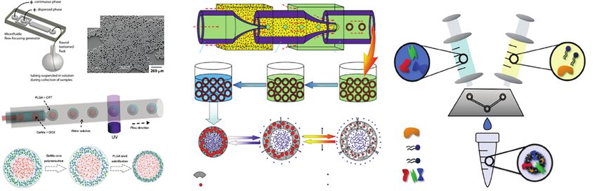
1.4 Applications of the Droplet-Derived Materials 19

particle size, size distribution, surface charge, and drug release profiles. Materials
synthesized by droplet microfluidics possess several advantages to overcome the
dilemma, which lie in the following aspects. First, droplet-synthesized materials
are highly tunable and uniform in size, structure, and encapsulation efficiency.
This provides a guarantee for maintaining a consistent release response and thus
for regulating the release rate. Second, the droplet-based drug delivery system
allows for a wide range of material choices, and multiple drugs could be loaded
simultaneously for investigating their synergetic effects. Third, by using different
matrix materials, various release profiles can be achieved under an external
stimulus, which are important for specific usages [127, 128].
 Many MP-based drug delivery platforms are developed through O/W single
emulsion, where the drugs are encapsulated into a biocompatible polymeric
particle matrix, including PLGA, poly- -caprolactone, and hydroxypropyl
methylcellulose acetate succinate (HPMCAS). The polymers used in O/W emul-
sions are typically dissolved in a volatile solvent that can evaporate or diffuse out
from the droplets. The size of MPs is primarily controlled by the droplet size and
how much the final droplet shrinks during solvent removal, an adjustable vari-
able by employing different polymer concentrations [124]. For example, Xu et al.
fabricated monodisperse biodegradable drug-loaded PLGA MPs by combining
the formation of droplets in a microfluidic flow-focusing generator with rapid
evaporation of solvent from the droplets (Figure 1.7a,b) [129]. By comparison,
they demonstrated that microfluidics-based, monodisperse MPs exhibited sig-
nificantly reduced burst release and slower release rates than conventional, poly-
disperse MPs of similar average sizes and overall loading of drug. Therefore, the
ability of droplet microfluidics to produce monodisperse particles for drug deliv-
ery has several practical advantages. In addition, the reduced shear stresses used
to prepare particles in a microfluidic device may assist in maintaining the bioac-
tivity of shear-sensitive biomolecular drugs. Given that the conventional emul-
sion approach typically produces aggregates that must be removed by filtration,
particles prepared using the microfluidic method can be produced with higher
yields, which is also a significant advantage particularly for expensive drugs.
 Single emulsions do not ensure the simultaneous loading of multiple ther-
apeutics, especially when the payloads present different solubility. Therefore,
double emulsions are also widely used in drug delivery applications. Li et al.
presented a new type of MPs with gelatin methacrylate (GelMa) cores and PLGA
shells for synergistic and sustained drug delivery applications (Figure 1.7c)
[130]. The MPs were fabricated by using GelMa aqueous solution and PLGA oil
solution as the raw materials of the microfluidic double-emulsion templates, in
which hydrophilic and hydrophobic actives, such as doxorubicin hydrochloride
(DOX, hydrophilic) and camptothecin (CPT, hydrophobic), could be loaded,
respectively. As the inner cores were polymerized in the microfluidics during
the formation of the double emulsion, the solute actives could be trapped in
the cores with high efficiency, and the rupture or fusion of the cores could be
avoided during the solidification of the MP shells with other actives. It was also
demonstrated that the core–shell MPs with DOX and CPT codelivery could sig-
nificantly reduce the viability of liver cancer cells. These features made the solid
core–shell MPs ideal for synergistic and sustained drug delivery applications.
Outer fluid Ethanol solution
 (a) (d) Middle fluid (e) Aqueous solution
 (A)
 (b) Inner
 fluid

 Injection tube Transition tube Collection tube
 (D) (C) (B)
 Washing Crosslinking

 (c) Microfluidic chip
 Microcapsules in water Microcapsules in oil O/W/O emulsions
 Drug loading

 (E) (F) (G)
 pHpKa
 DPPC
 pH-responsive chitosan microcapsule membrane Magnetic nanoparticle Membrane
 Temperature-responsive sub-microsphere Encapsulated drug
 Proteins

Figure 1.7 (a, b) Schematic illustration of the procedure to fabricate monodisperse polymer MPs (a), and scanning electron microscopy images of
monodisperse PLGA MPs with a narrow size distribution (b). Source: Adapted with permission from Xu et al. [129]. Copyright 2009, John Wiley & Sons. (c)
Schematic diagram of a capillary microfluidic system for generating the W/O/W double-emulsion templates with polymerized cores and the fabrication
process of the drug-loaded GelMa–PLGA core–shell MPs. Source: Adapted with permission from Li et al. [130]. Copyright 2017, Springer Nature. (d) Schematic
illustration of fabrication process and controlled release mechanism of the proposed multi-stimuli-responsive microcapsules. Source: Adapted with
permission from Wei et al. [131]. Copyright 2014, John Wiley & Sons. (e) Schematic process for the assembly of biomimetic nanovesicles using NanoAssemblr
platform. Source: Adapted with permission from Molinaro et al. [132]. Copyright 2018, John Wiley & Sons. (f ) Schematic of the two-stage microfluidic chip for
synthesizing the lipid-PLGA hybrid NPs. Source: Adapted with permission from Feng et al. [133]. Copyright 2015, American Institute of Physics. (g)
High-resolution scanning electron microscopy images of TOPSi NPs, TOPSi@AcDEX nanosystems, and TOPSi@AcDEX@CCM nanovaccines. Source: Adapted
with permission from Fontana et al. [134]. Copyright 2017, John Wiley & Sons.
(f) (g)
 Water
 PLGA

 Lipid-PEG
 PLGA-NPs

 Lipid-PEG

 Lipid

Figure 1.7 (Continued)
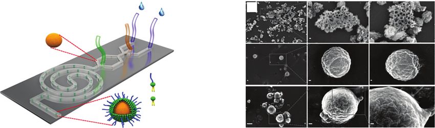
22 1 Micro/Nanostructured Materials from Droplet Microfluidics

 In passive modes, drug release depends on molecular diffusion and matrix
 degradation, and the release profile generally shows an initial burst step and
 a following sustained pattern. MPs with multi-stimuli-responsive properties
 have been prepared by droplet microfluidics to achieve enhanced control over
 drug release. For instance, based on W/O/W emulsions, Wei et al. fabricated
 microcapsules composed of cross-linked chitosan acting as a pH-responsive
 capsule membrane (Figure 1.7d) [131]. When the local pH was lower than
 the pK a of chitosan, the membrane swelled, resulting in a high drug release
 rate. The release rate could be further tuned by varying the interspace distance
 between the nanosphere in the capsule membrane, which was achieved by
 the temperature-regulated volume change of the nanospheres. In addition,
 the magnetic NPs were embedded to realize “site-specific targeting,” and the
 temperature-responsive submicrospheres were embedded to serve as “mi-
 crovalves.” Therefore, this kind of multi-stimuli-responsive MPs provided a new
 direction for designing “intelligent” controlled release systems and expected to
 realize more rational drug administration.
 NMs with unique physical and chemical properties can also serve as drug
 carriers. In addition, more recently, advances in biomimicry, i.e. the biologically
 inspired design of materials, has spurred the development of novel strategies
 to bestow NMs with multiple functionalities necessary to negotiate biological
 barriers. Current approaches for drug delivery carriers include mimicking of
 leukocytes, red blood cell platelets, and cancer cells to achieve superior delivery
 of therapeutics compared to conventional NMs. These biomimetic strategies
 demonstrated innate biological features and intrinsic functionalities typical
 of the donor cell source. For example, leukocyte-like nanovesicles showed
 prolonged circulation and preferential targeting of inflamed vasculature, while
 platelet-like NPs displayed platelet-mimicking properties such as adhesion to
 damaged vasculature and binding to platelet-adhering pathogens. Molinaro
 et al. successfully applied the microfluidics-based NanoAssemblr platform
 for the incorporation of membrane proteins within the bilayer of biomimetic
 nanovesicles (leukosomes) (Figure 1.7e) [132]. The physical, pharmaceutical, and
 biological properties of microfluidics-formulated leukosomes (called NA-Leuko)
 were characterized, which showed extended shelf life and retention of the biolog-
 ical functions of donor cells (i.e. macrophage avoidance and targeting of inflamed
 vasculature). Thus, the microfluidic approach represents as a universal, versatile,
 robust, and scalable tool, which is extensively used for the manufacturing of
 biomimetic nanovesicles.
 Core–shell NPs have gained increasing interest for drug delivery because
 of their high flexibility and biocompatibility. However, it is too complex and
 laborious to synthesize controlled core–shell NPs in bulk approaches. Microflu-
 idic systems integrated with the precise flow control and hydrodynamic flow
 focusing have been applied to fabricate size-tunable lipid–polymer NPs. Jiang’s
 group designed a two-stage, high-throughput microfluidic chip to fabricate
 monodisperse lipid–polymer NPs with a controlled size (Figure 1.7f ) [133]. The
 core of the NPs was a PLGA polymer and the shell consisted of dipalmitoyl phos-
 phatidylcholine (DPPC), 1,2-distearoyl-sn-glycero-3-phosphoethanolamine-N-
 poly(ethylene glycol) (DSPE-PEG), and cholesterol. It showed that the higher
 the flow rate, the better the mixing performance was, which led to smaller sized
You can also read