KAH-MEG-5 - Quick Setup Guide - GRAPHICAL USER INTERFACE CONTROLLER - Grass Valley
←
→
Page content transcription
If your browser does not render page correctly, please read the page content below
KAH-MEG-5
GRAPHICAL USER INTERFACE CONTROLLER

Quick Setup Guide

13-06530-010
2021-01-25
Notices

FCC Compliance
          In order to comply with FCC/CFR47: Part 15 regulations, it is necessary to use high-quality,
          triple-screened Media or Monitor cable assemblies with integrated ferrite suppression at
          both ends.

Patent Information
          This product may be protected by one or more patents.
          For further information, please visit: www.grassvalley.com/patents/

Copyright and Trademark Notice
          Grass Valley®, GV® and the Grass Valley logo and/or any of the Grass Valley products listed
          in this document are trademarks or registered trademarks of GVBB Holdings SARL, Grass
          Valley USA, LLC, or one of its affiliates or subsidiaries. All other intellectual property rights
          are owned by GVBB Holdings SARL, Grass Valley USA, LLC, or one of its affiliates or
          subsidiaries. All third party intellectual property rights (including logos or icons) remain the
          property of their respective owners.
          Copyright © 2020 - 2021 GVBB Holdings SARL and Grass Valley USA, LLC. All rights reserved.
          Specifications are subject to change without notice.

Terms and Conditions
          Please read the following terms and conditions carefully. By using Kahuna MEG
          documentation, you agree to the following terms and conditions.
          Grass Valley hereby grants permission and license to owners of Kahuna MEG to use their
          product manuals for their own internal business use. Manuals for Grass Valley products may
          not be reproduced or transmitted in any form or by any means, electronic or mechanical,
          including photocopying and recording, for any purpose unless specifically authorized in
          writing by Grass Valley.
          A Grass Valley manual may have been revised to reflect changes made to the product
          during its manufacturing life. Thus, different versions of a manual may exist for any given
          product. Care should be taken to ensure that one obtains the proper manual version for a
          specific product serial number.
          Information in this document is subject to change without notice and does not represent a
          commitment on the part of Grass Valley.
          Warranty information is available from the Legal Terms and Conditions section of Grass
          Valley’s website (www.grassvalley.com).

          Title           KAH-MEG-5 Quick Setup Guide

          Part Number     13-06530-010

          Revision        2021-01-25, 09:27

ii
Kahuna MEG
                                                                                          Quick Setup Guide

Important Safety Information
          This section provides important safety guidelines for operators and service personnel.
          Specific warnings and cautions appear throughout the manual where they apply. Please
          read and follow this important information, especially those instructions related to the risk
          of electric shock or injury to persons.

Symbols and Their Meanings

                        Indicates that dangerous high voltage is present within the equipment
                        enclosure that may be of sufficient magnitude to constitute a risk of electric
                        shock.

                        Indicates that the user, operator or service technician should refer to the product
                        manuals for important operating, maintenance, or service instructions.

                        This is a prompt to note the fuse rating when replacing fuses. The fuse
                        referenced in the text must be replaced with one having the ratings indicated.

                        Identifies a protective grounding terminal which must be connected to earth
                        ground prior to making any other equipment connections.

                        Identifies an external protective grounding terminal which may be connected to
                        earth ground as a supplement to an internal grounding terminal.

                        Indicates that static sensitive components are present, which may be damaged
                        by electrostatic discharge. Use anti-static procedures, equipment and surfaces
                        during servicing.

                        Indicates that the equipment has more than one power supply cord, and that all
                        power supply cords must be disconnected before servicing to avoid electric
                        shock.

                        The presence of this symbol in or on Grass Valley equipment means that it has
                        been tested and certified as complying with applicable Underwriters Laboratory
                        (UL) regulations and recommendations for USA.

                        The presence of this symbol in or on Grass Valley equipment means that it has
                        been tested and certified as complying with applicable Canadian Standard
                        Association (CSA) regulations and recommendations for USA/Canada.

                        The presence of this symbol in or on Grass Valley equipment means that it has
                        been tested and certified as complying with applicable Underwriters Laboratory
                        (UL) regulations and recommendations for USA/Canada.

                                                                                                          iii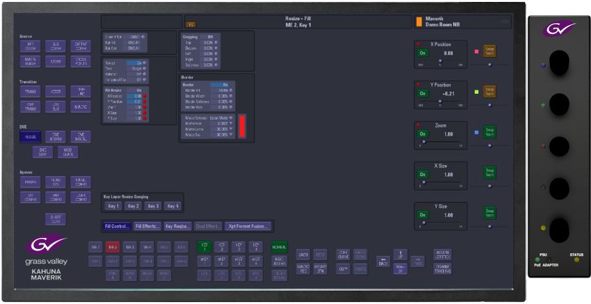
Notices

                        The presence of this symbol in or on Grass Valley equipment means that it has
                        been tested and certified as complying with applicable Intertek Testing Services
                        regulations and recommendations for USA/Canada.

                        The presence of this symbol in or on Grass Valley product means that it complies
                        with all applicable European Union (CE) directives.

                        The presence of this symbol in or on Grass Valley product means that it complies
                        with safety of laser product applicable standards.

Warnings
                   A warning indicates a possible hazard to personnel, which may cause injury or
                   death. Observe the following general warnings when using or working on this
                   equipment:
           •   Appropriately listed/certified mains supply power cords must be used for the
               connection of the equipment to the rated mains voltage.
           •   This product relies on the building's installation for short-circuit (over-current)
               protection. Ensure that a fuse or circuit breaker for the rated mains voltage is used on
               the phase conductors.
           •   Any instructions in this manual that require opening the equipment cover or enclosure
               are for use by qualified service personnel only.
           •   Do not operate the equipment in wet or damp conditions.
           •   This equipment is grounded through the grounding conductor of the power cords. To
               avoid electrical shock, plug the power cords into a properly wired receptacle before
               connecting the equipment inputs or outputs.
           •   Route power cords and other cables so they are not likely to be damaged. Properly
               support heavy cable bundles to avoid connector damage.
           •   Disconnect power before cleaning the equipment. Do not use liquid or aerosol
               cleaners; use only a damp cloth.
           •   Dangerous voltages may exist at several points in this equipment. To avoid injury, do
               not touch exposed connections and components while power is on.
           •   High leakage current may be present. Earth connection of product is essential before
               connecting power.
           •   Prior to servicing, remove jewelry such as rings, watches, and other metallic objects.
           •   To avoid fire hazard, use only the fuse type and rating specified in the service
               instructions for this product, or on the equipment.
           •   To avoid explosion, do not operate this equipment in an explosive atmosphere.
           •   Use proper lift points. Do not use door latches to lift or move equipment.
           •   Avoid mechanical hazards. Allow all rotating devices to come to a stop before servicing.
           •   Have qualified service personnel perform safety checks after any service.

iv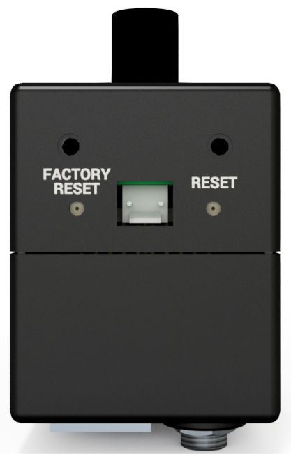
Kahuna MEG
                                                                                       Quick Setup Guide

Cautions
                     A caution indicates a possible hazard to equipment that could result in equipment
                     damage. Observe the following cautions when operating or working on this
                     equipment:
             •   This equipment is meant to be installed in a restricted access location.
             •   When installing this equipment, do not attach the power cord to building surfaces.
             •   Products that have no on/off switch, and use an external power supply must be
                 installed in proximity to a main power outlet that is easily accessible.
             •   Use the correct voltage setting. If this product lacks auto-ranging power supplies,
                 before applying power ensure that each power supply is set to match the power
                 source.
             •   Provide proper ventilation. To prevent product overheating, provide equipment
                 ventilation in accordance with the installation instructions.
             •   Do not operate with suspected equipment failure. If you suspect product damage or
                 equipment failure, have the equipment inspected by qualified service personnel.
             •   To reduce the risk of electric shock, do not perform any servicing other than that
                 contained in the operating instructions unless you are qualified to do so. Refer all
                 servicing to qualified service personnel.
             •   This unit may have more than one power supply cord. Disconnect all power supply
                 cords before servicing to avoid electric shock.
             •   Follow static precautions at all times when handling this equipment. Servicing should
                 be done in a static-free environment.
             •   To reduce the risk of electric shock, plug each power supply cord into separate branch
                 circuits employing separate service grounds.

Electrostatic Discharge (ESD) Protection
                   Electrostatic discharge occurs when electronic components are improperly
                   handled and can result in intermittent failure or complete damage adversely
                   affecting an electrical circuit. When you remove and replace any card from a frame
           always follow ESD-prevention procedures:
             • Ensure that the frame is electrically connected to earth ground through the power cord
               or any other means if available.
             • Wear an ESD wrist strap ensuring that it makes good skin contact. Connect the
               grounding clip to an unpainted surface of the chassis frame to safely ground unwanted
               ESD voltages. If no wrist strap is available, ground yourself by touching the unpainted
               metal part of the chassis.
             • For safety, periodically check the resistance value of the antistatic strap, which should
               be between 1 and 10 megohms.
             • When temporarily storing a card make sure it is placed in an ESD bag.
             • Cards in an earth grounded metal frame or casing do not require any special ESD
               protection.

                                                                                                       v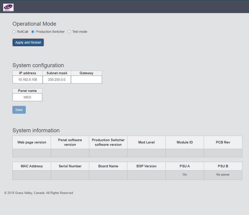
Notices

Battery Handling
                   This product may include a backup battery. There is a danger of explosion if the
                   battery is replaced incorrectly. Replace the battery only with the same or equivalent
                   type recommended by the manufacturer. Dispose of used batteries according to
           the manufacturer’s instructions. Before disposing of your Grass Valley equipment, please
           review the Disposal and Recycling Information at:
             http://www.grassvalley.com/assets/media/5692/Take-Back_Instructions.pdf

Cautions for LCD and TFT Displays
                   Excessive usage may harm your vision. Rest for 10 minutes for every 30 minutes of
                   usage.
                    If the LCD or TFT glass is broken, handle glass fragments with care when disposing
           of them. If any fluid leaks out of a damaged glass cell, be careful not to get the liquid crystal
           fluid in your mouth or skin. If the liquid crystal touches your skin or clothes, wash it off
           immediately using soap and water. Never swallow the fluid. The toxicity is extremely low
           but caution should be exercised at all times.

Mesures de sécurité et avis importants
           La présente section fournit des consignes de sécurité importantes pour les opérateurs et le
           personnel de service. Des avertissements ou mises en garde spécifiques figurent dans le
           manuel, dans les sections où ils s’appliquent. Prenez le temps de bien lire les consignes et
           assurez-vous de les respecter, en particulier celles qui sont destinées à prévenir les
           décharges électriques ou les blessures.

Signification des symboles utilisés

                         Signale la présence d’une tension élevée et dangereuse dans le boîtier de
                         l’équipement ; cette tension peut être suffisante pour constituer un risque de
                         décharge électrique.

                         Avertit l'utilisateur, l’opérateur ou le technicien de maintenance que des
                         instructions importantes relatives à l'utilisation et à l'entretien se trouvent dans
                         la documentation accompagnant l’équipement.

                         Invite l'utilisateur, l’opérateur ou le technicien de maintenance à prendre note du
                         calibre du fusible lors du remplacement de ce dernier. Le fusible auquel il est fait
                         référence dans le texte doit être remplacé par un fusible du même calibre.

                         Identifie une borne de mise à la terre de protection. Il faut relier cette borne à la
                         terre avant d’effectuer toute autre connexion à l’équipement.

vi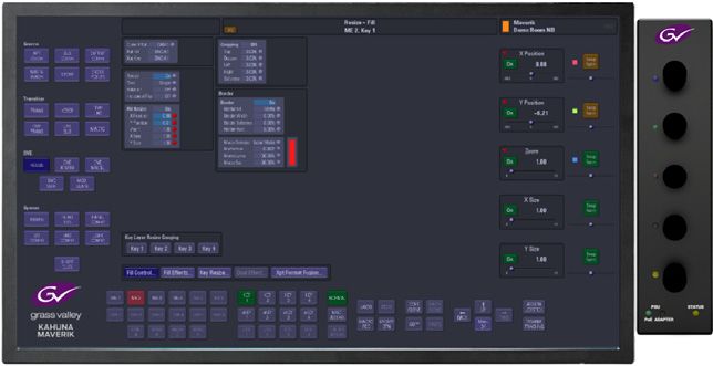
Kahuna MEG
                                                                                        Quick Setup Guide

                       Identifie une borne de mise à la terre externe qui peut être connectée en tant
                       que borne de mise à la terre supplémentaire.

                       Signale la présence de composants sensibles à l’électricité statique et qui sont
                       susceptibles d’être endommagés par une décharge électrostatique. Utilisez des
                       procédures, des équipements et des surfaces antistatiques durant les
                       interventions d’entretien.

                       Le symbole ci-contre signifie que l’appareil comporte plus d’un cordon
                       d'alimentation et qu’il faut débrancher tous les cordons d'alimentation avant
                       toute opération d’entretien, afin de prévenir les chocs électriques.

                       La marque UL certifie que l’appareil visé a été testé par Underwriters Laboratory
                       (UL) et reconnu conforme aux exigences applicables en matière de sécurité
                       électrique en vigueur au Canada et aux États-Unis.

                       La marque C-CSA-US certifie que l’appareil visé a été testé par l'Association
                       canadienne de normalisation (CSA) et reconnu conforme aux exigences
                       applicables en matière de sécurité électrique en vigueur au Canada et aux États-
                       Unis.

                       La marque C-UL-US certifie que l’appareil visé a été testé par Underwriters
                       Laboratory (UL) et reconnu conforme aux exigences applicables en matière de
                       sécurité électrique en vigueur au Canada et aux États-Unis.

                       La marque ETL Listed d’Intertek pour le marché Nord-Américain certifie que
                       l’appareil visé a été testé par Intertek et reconnu conforme aux exigences
                       applicables en matière de sécurité électrique en vigueur au Canada et aux États-
                       Unis.

                       Le marquage CE indique que l’appareil visé est conforme aux exigences
                       essentielles des directives applicables de l’Union européenne en matière de
                       sécurité électrique, de compatibilité électromagnétique et de conformité
                       environnementale.

                       Le symbole ci-contre sur un appareil Grass Valley ou à l’intérieur de l’appareil
                       indique qu’il est conforme aux normes applicables en matière de sécurité laser.

Avertissements
                  Les avertissements signalent des conditions ou des pratiques susceptibles
                  d’occasionner des blessures graves, voire fatales. Veuillez vous familiariser avec les
                  avertissements d’ordre général ci-dessous :
           • Un cordon d’alimentation dûment homologué doit être utilisé pour connecter
             l’appareil à une tension de secteur de 120 V CA ou 240 V CA.
           • La protection de ce produit contre les courts-circuits (surintensités) dépend de
             l’installation électrique du bâtiment. Assurez-vous qu'un fusible ou un disjoncteur pour
             120 V CA ou 240 V CA est utilisé sur les conducteurs de phase.

                                                                                                          vii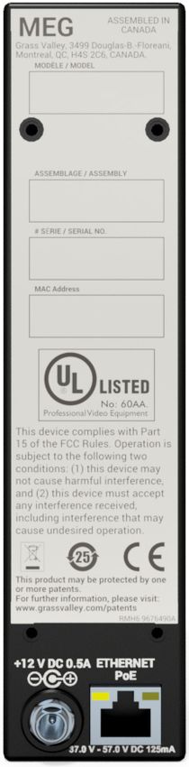
Notices

            • Dans le présent manuel, toutes les instructions qui nécessitent d’ouvrir le couvercle de
              l’équipement sont destinées exclusivement au personnel technique qualifié.
            • N’utilisez pas cet appareil dans un environnement humide.
            • Cet équipement est mis à la terre par le conducteur de mise à la terre des cordons
              d’alimentation. Pour éviter les chocs électriques, branchez les cordons d’alimentation
              sur une prise correctement câblée avant de brancher les entrées et sorties de
              l’équipement.
            • Acheminez les cordons d’alimentation et autres câbles de façon à ce qu’ils ne risquent
              pas d’être endommagés. Supportez correctement les enroulements de câbles afin de
              ne pas endommager les connecteurs.
            • Coupez l’alimentation avant de nettoyer l’équipement. Ne pas utiliser de nettoyants
              liquides ou en aérosol. Utilisez uniquement un chiffon humide.
            • Des tensions dangereuses peuvent exister en plusieurs points dans cet équipement.
              Pour éviter toute blessure, ne touchez pas aux connexions ou aux composants exposés
              lorsque l’appareil est sous tension.
            • Avant de procéder à toute opération d’entretien ou de dépannage, enlevez tous vos
              bijoux (notamment vos bagues, votre montre et autres objets métalliques).
            • Pour éviter tout risque d’incendie, utilisez uniquement les fusibles du type et du calibre
              indiqués sur l’équipement ou dans la documentation qui l’accompagne.
            • Ne pas utiliser cet appareil dans une atmosphère explosive.
            • Présence possible de courants de fuite. Un raccordement à la masse est indispensable
              avant la mise sous tension.
            • Après tout travail d’entretien ou de réparation, faites effectuer des contrôles de sécurité
              par le personnel technique qualifié.

Mises en garde
                     Les mises en garde signalent des conditions ou des pratiques susceptibles
                     d’endommager l’équipement. Veuillez vous familiariser avec les mises en garde ci-
                     dessous :
            •   L’appareil est conçu pour être installé dans un endroit à accès restreint.
            •   Au moment d’installer l’équipement, ne fixez pas les cordons d’alimentation aux
                surfaces intérieures de l’édifice.
            •   Les produits qui n'ont pas d’interrupteur marche-arrêt et qui disposent d’une source
                d’alimentation externe doivent être installés à proximité d'une prise de courant facile
                d’accès.
            •   Si l’équipement n’est pas pourvu d’un modules d’alimentation auto-adaptables, vérifiez
                la configuration de chacun des modules d'alimentation avant de les mettre sous
                tension.
            •   Assurez une ventilation adéquate. Pour éviter toute surchauffe du produit, assurez une
                ventilation de l’équipement conformément aux instructions d’installation.
            •   N’utilisez pas l’équipement si vous suspectez un dysfonctionnement du produit. Faites-
                le inspecter par un technicien qualifié.
            •   Pour réduire le risque de choc électrique, n'effectuez pas de réparations autres que
                celles qui sont décrites dans le présent manuel, sauf si vous êtes qualifié pour le faire.

viii
Kahuna MEG
                                                                                        Quick Setup Guide

              Confiez les réparations à un technicien qualifié. La maintenance doit se réaliser dans un
              milieu libre d’électricité statique.
            • L’appareil peut comporter plus d’un cordon d'alimentation. Afin de prévenir les chocs
              électriques, débrancher tous les cordons d'alimentation avant toute opération
              d’entretien.
            • Veillez à toujours prendre les mesures de protection antistatique appropriées quand
              vous manipulez l’équipement.
            • Pour réduire le risque de choc électrique, branchez chaque cordon d'alimentation dans
              des circuits de dérivation distincts utilisant des zones de service distinctes.

Protection contre les décharges électrostatiques (DES)
                  Une décharge électrostatique peut se produire lorsque des composants
                  électroniques ne sont pas manipulés de manière adéquate, ce qui peut entraîner
                  des défaillances intermittentes ou endommager irrémédiablement un circuit
          électrique. Au moment de remplacer une carte dans un châssis, prenez toujours les
          mesures de protection antistatique appropriées :
            • Assurez-vous que le châssis est relié électriquement à la terre par le cordon
              d'alimentation ou tout autre moyen disponible.
            • Portez un bracelet antistatique et assurez-vous qu'il est bien en contact avec la peau.
              Connectez la pince de masse à une surface non peinte du châssis pour détourner à la
              terre toute tension électrostatique indésirable. En l’absence de bracelet antistatique,
              déchargez l’électricité statique de votre corps en touchant une surface métallique non
              peinte du châssis.
            • Pour plus de sécurité, vérifiez périodiquement la valeur de résistance du bracelet
              antistatique. Elle doit se situer entre 1 et 10 mégohms.
            • Si vous devez mettre une carte de côté, assurez-vous de la ranger dans un sac
              protecteur antistatique.
            • Les cartes qui sont reliées à un châssis ou boîtier métallique mis à la terre ne
              nécessitent pas de protection antistatique spéciale.

Manipulation de la pile
                  Ce produit peut inclure une pile de sauvegarde. Il y a un risque d'explosion si la pile
                  est remplacée de manière incorrecte. Remplacez la pile uniquement par un modèle
                  identique ou équivalent recommandé par le fabricant. Disposez des piles usagées
          conformément aux instructions du fabricant. Avant de vous séparer de votre équipement
          Grass Valley, veuillez consulter les informations de mise au rebut et de recyclage à:
            http://www.grassvalley.com/assets/media/5692/Take-Back_Instructions.pdf

Précautions pour les écrans LCD et TFT
                  Regarder l’écran pendant une trop longue période de temps peut nuire à votre
                  vision. Prenez une pause de 10 minutes, après 30 minutes d’utilisation.

                                                                                                       ix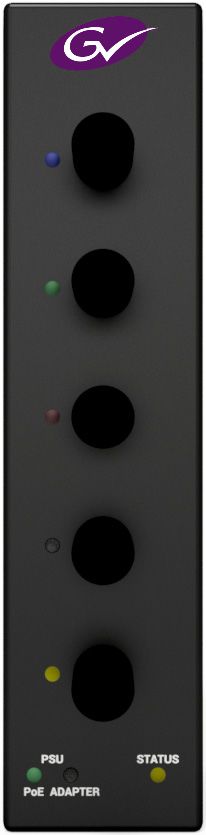
Notices

          Si l'écran LCD ou TFT est brisé, manipulez les fragments de verre avec précaution au
          moment de vous en débarrasser. veillez à ce que le cristal liquide n'entre pas en contact
          avec la peau ou la bouche. En cas de contact avec la peau ou les vêtements, laver
          immédiatement à l'eau savonneuse. Ne jamais ingérer le liquide. La toxicité est
          extrêmement faible, mais la prudence demeure de mise en tout temps.

Environmental Information

          European (CE) WEEE directive.

          This symbol on the product(s) means that at the end of life disposal it should not be mixed
          with general waste.

          Visit www.grassvalley.com for recycling information.
          Grass Valley believes this environmental information to be correct but cannot guarantee its
          completeness or accuracy since it is based on data received from sources outside our
          company. All specifications are subject to change without notice.
          If you have questions about Grass Valley environmental and social involvement (WEEE,
          RoHS, REACH, etc.), please contact us at environment@grassvalley.com .

x
Kahuna MEG
Quick Setup Guide
Safety and EMC Standards
This equipment complies with the following standards:
Safety Standards
Information Technology Equipment - Safety Part 1
EN60950-1: 2006
Safety of Information Technology Equipment Including Electrical Business Equipment.
UL1419 (4th Edition)
Standard for Safety – Professional Video and Audio equipment (UL file number E193966)
EMC Standards
This unit conforms to the following standards:
EN55032:2015 (Class A)
Electromagnetic Compatibility of multimedia equipment - Emission requirements
EN61000-3-2:2014 (Class A)
Electromagnetic Compatibility - Limits for harmonic current emissions
EN61000-3-3:2013
Electromagnetic Compatibility - Limits of voltage changes, voltage fluctuations and flicker
EN55103-2:2009 (Environment E2)
Electromagnetic Compatibility, Product family standard for audio, video, audio-visual and
entertainment lighting control apparatus for professional use. Part 2. Immunity
WARNING
This equipment is compliant with Class A of CISPR 32. In a residential
environment this equipment may cause radio interference.
FCC / CFR 47:Part 15 (Class A)
Federal Communications Commission Rules Part 15, Subpart B
Caution to the user that changes or modifications not expressly approved by the party
responsible for compliance could void the user's authority to operate the equipment.
xiNotices
Note: This equipment has been tested and found to comply with the
limits for a Class A digital device, pursuant to part 15 of the FCC
Rules. These limits are designed to provide reasonable
protection against harmful interference when the equipment is
operated in a commercial environment.
This equipment generates, uses, and can radiate radio
frequency energy and, if not installed and used in accordance
with the instruction manual, may cause harmful interference to
radio communications.
Operation of this equipment in a residential area is likely to
cause harmful interference in which case the user will be
required to correct the interference at his own expense.
EMC Performance of Cables and Connectors
Grass Valley products are designed to meet or exceed the requirements of the appropriate
European EMC standards. In order to achieve this performance in real installations it is
essential to use cables and connectors with good EMC characteristics.
All signal connections (including remote control connections) shall be made with screened
cables terminated in connectors having a metal shell. The cable screen shall have a large-
area contact with the metal shell.
SIGNAL/DATA PORTS
For unconnected signal/data ports on the unit, fit shielding covers. For example, fit EMI
blanking covers to SFP+ type ports; and fit 75 Ώ RF terminators to BNC type ports.
COAXIAL CABLES
Coaxial cables connections (particularly serial digital video connections) shall be made with
high-quality double-screened coaxial cables such as Belden 8281 or BBC type PSF1/2M and
Belden 1694A (for 3Gbps).
D-TYPE CONNECTORS
D-type connectors shall have metal shells making good RF contact with the cable screen.
Connectors having “dimples” which improve the contact between the plug and socket
shells, are recommended.
xiiTable of Contents
FCC Compliance. . . . . . . . . . . . . . . . . . . . . . . . . . . . . . . . . . . . . . . . . . . . . . . . . . . . . . . . . . . . . . . . . . . ii
Patent Information . . . . . . . . . . . . . . . . . . . . . . . . . . . . . . . . . . . . . . . . . . . . . . . . . . . . . . . . . . . . . . . . ii
Copyright and Trademark Notice. . . . . . . . . . . . . . . . . . . . . . . . . . . . . . . . . . . . . . . . . . . . . . . . . . . ii
Safety and EMC Standards . . . . . . . . . . . . . . . . . . . . . . . . . . . . . . . . . . . . . . . . . . . . . . . . . . . . . . . . xi
Safety Standards . . . . . . . . . . . . . . . . . . . . . . . . . . . . . . . . . . . . . . . . . . . . . . . . . . . . . . . . . . . . . xi
EMC Standards . . . . . . . . . . . . . . . . . . . . . . . . . . . . . . . . . . . . . . . . . . . . . . . . . . . . . . . . . . . . . . . xi
EMC Performance of Cables and Connectors . . . . . . . . . . . . . . . . . . . . . . . . . . . . . . . . . . xii
1 Kahuna MEG . . . . . . . . . . . . . . . . . . . . . . . . . . . . . . . . . . . . . . . . . . . 3
Kahuna MEG Overview . . . . . . . . . . . . . . . . . . . . . . . . . . . . . . . . . . . . . . . . . . . . . . . . . . . . . . . . . . . . 3
What is required:. . . . . . . . . . . . . . . . . . . . . . . . . . . . . . . . . . . . . . . . . . . . . . . . . . . . . . . . . . . . . . 3
MEG IP Address Setup . . . . . . . . . . . . . . . . . . . . . . . . . . . . . . . . . . . . . . . . . . . . . . . . . . . . . . . . . 4
MEG Module Factory Reset . . . . . . . . . . . . . . . . . . . . . . . . . . . . . . . . . . . . . . . . . . . . . . . . . . . . 4
Attaching the MEG module to a Monitor . . . . . . . . . . . . . . . . . . . . . . . . . . . . . . . . . . . . . . . 6
Connecting the MEG module and Setup with Kahuna . . . . . . . . . . . . . . . . . . . . . . . . . . 9
When Powered Up and Working. . . . . . . . . . . . . . . . . . . . . . . . . . . . . . . . . . . . . . . . . . . . . . 10
System Connection . . . . . . . . . . . . . . . . . . . . . . . . . . . . . . . . . . . . . . . . . . . . . . . . . . . . . . . . . . 10
Setting up the MEG module with Kahuna . . . . . . . . . . . . . . . . . . . . . . . . . . . . . . . . . . . . .11
Contact Us . . . . . . . . . . . . . . . . . . . . . . . . . . . . . . . . . . . . . . . . . . . . . . . 13
1Table of Contents 2
Kahuna MEG

Kahuna MEG Overview
        Kahuna MEG is designed to work with an external touch screen Graphical User Interface.
        The metal bracket the MEG module attaches to, is designed to fit a VESA 75/100 stand,
        which allows the MEG to be situated on the right hand side of the monitor to align with the
        on-screen parameter controls.
        Once connected to a network and setup to work with the Kahuna system, the five rotary
        controls can be used to finely adjust parameter controls in the Kahuna menus, giving the
        user precise control.
        The diagram below displays a touch screen monitor with a Kahuna MEG attached.

                                                                                  Kahuna MEG

                                                                                  Rotary Controls

        What is required:
          •   1x MEG module (supplied)
          •   1x MEG module VESA Bracket kit (supplied)
          •   1x Ethernet Cables (supplied).
          •   1x External power supply (supplied).

                                                                                                   3
Kahuna MEG
MEG IP Address Setup
MEG IP Address Setup
IMPORTANT: Please make sure that the Kahuna system is running
V9.4r1 software or greater before setting up and connecting the
MEG module to the system.
It is easier to setup the MEG module before attaching it to a monitor. The first thing to do is
to setup the IP address of the MEG module so that Kahuna is able to communicate with it.
MEG Module Factory Reset
At the bottom of the MEG module is a “Factory Reset” button. This is used reset the IP
address and reboot the MEG module if the MEG module has been setup before and the
current IP address i not known. Carefully depress an hold the Factory Reset button for 10
seconds. The LEDs will flash a few times, after 10 seconds has passed, the IP address is reset
to the factory IP address of “192.168.1.1” and reboot.
Connect the MEG module to the external power supply and power it up. Connect a PC or
laptop directly to the MEG module via a network cable to the RJ45 port. If this is the first
time the MEG module is being set up, set the PC/Laptop IP Address to within the range of
the default IP address of the MEG module which is “192.168.1.1” so for example, set the
PC/laptop IP address to “192.168.1.2”.
Once this is done, open a browser window on the PC/laptop and type in the default IP
address, the “Web Page” for the MEG module will open.
In the Web Page window, select “Production Switcher”, then in the “System
Configuration” area enter an IP address that is within the range of the Kahuna mainframe
and enter Subnet Mask.
4Kahuna MEG
Quick Setup Guide
For example, if the Kahuna mainframe has an IP address of “178.162.20.86/19” then enter
an IP address of “178.162.20.87” and a Subnet Mask of “255.255.224”. You can also give
the panel an unique name if required.
Finally click on the “Save” button. The new IP address and Subnet Mask has been updated
and the Meg module is ready to use with the Kahuna system.
Note: All applicable software updates for MEG are done when the Kahuna
system software or the Maverik panel software is updated.
5Kahuna MEG
Attaching the MEG module to a Monitor
Attaching the MEG module to a Monitor
The mounting bracket that the MEG is mounted on is supplied in 3 pieces and includes the
assembly screws:
• VESA bracket
• Spacer
• MEG bracket
• Assembly screws
VESA Bracket Spacer Bar MEG Bracket
The spacer bar attaches to the VESA bracket with 3x screws (shown below) . On the back of
the VESA bracket when the spacer is mounted are three vertical slider slots where the three
screws go through to attach the spacer bar. The slider slots allow the spacer bar (and MEG
bracket when attached) to be adjusted vertically (up and down). Hold the spacer on the
VESA bracket and attach the spacer bar.
Slider Slots
Attach the screws from this side and screws
Top View
Spacer
VESA Bracket
6Kahuna MEG
Quick Setup Guide
With the spacer bar now fixed to the VESA bracket, the MEG bracket attaches to the spacer
bar with 2x screws (as shown below). On the MEG bracket there are two horizontal slider
slots that allow the MEG bracket to be moved and positioned forward or backward. Hold
the MEG bracket to the spacer bar and attach.
Slider slots
and screws
Slider slots to mount
the VESA bracket onto
the monitor
Attach the screws
from this side
The MEG module has 4x screw holes on the back that line up with the holes on the MEG
bracket. Fix the MEG module to the bracket with 4x screws
Rear of
MEG Module
Screw
Holes
MEG Module
Attached to Bracket
7Kahuna MEG
Attaching the MEG module to a Monitor
The cut-outs on the VESA bracket allow for different size stand brackets and monitors.
When mounting the MEG and VESA bracket to the back of a monitor, the MEG module must
be situated on the right side of the monitor. The MEG VESA bracket attaches to the rear of
the monitor to the “VESA 75 or VESA 100” attachment holes.
The VESA stand bracket and the MEG VESA bracket attach to the monitor with the correct
screws (not supplied).
Note: Some monitors have the On/Off button and control buttons running
down the right side of the monitor. When fitting the VESA bracket to the
monitor, make sure to leave enough room to allow you to use the monitor
buttons.
8Kahuna MEG
Quick Setup Guide
Connecting the MEG module and Setup with Kahuna
IMPORTANT: Please make sure that the Kahuna system is running
V9.4r1 software or greater before setting up and connecting the MEG
module to the system.
The RJ45 PoE/Network connector at rear of the MEG module is used to connected directly
to a network switch.
Note: It is recommended that you use the (supplied) external power supply
to power the MEG module.
You can also connect the MEG module (without the supplied external power supply) to a
Power Over Ethernet (PoE) network switch. Rated 37.0V - 57.0V DC 125mA.
Reset Button
Factory Reset
Button
External PSU
Connector
Network
Connector
At the bottom of the MEG module is a “Factory Reset” button. This is used reset the IP
address and reboot the MEG module. Carefully depress an hold the Factory Reset button for
10 seconds. The LEDs will flash a few times, after 10 seconds has passed, the IP address is
reset to the factory IP address of “192.168.1.1” and reboot.
Note: The 2 Pin connector is not currently used.
The “Reset” button just resets the MEG module (reboot). The current IP address is
maintained.
9Kahuna MEG
Connecting the MEG module and Setup with Kahuna
When Powered Up and Working
When setup and working, the LEDs on the MEG module will light up according to the
number of parameter controls in the current menu, 3 or 5. The “PSU ADAPTER” LED will
light green and the “Status” LED will light green.
Parameter
LEDs
PSU LED Status LED
(PoE) and Adapter
System Connection
The diagram below displays how the MEG module connects to the Kahuna mainframe.
MEG with Monitor
Kahuna Mainframe
Network Switch
(not supplied)
Network
Network connection to
the Kahuna Mainframe
Maverik Control Surface
Note: When connecting the external PSU to the MEG module, make sure
that the PSU is supported and not hanging from the MEG module.
10Kahuna MEG
Quick Setup Guide
Setting up the MEG module with Kahuna
Once the MEG module is connected to the Kahuna mainframe, the MEG module needs to
be recognized by the Kahuna software.
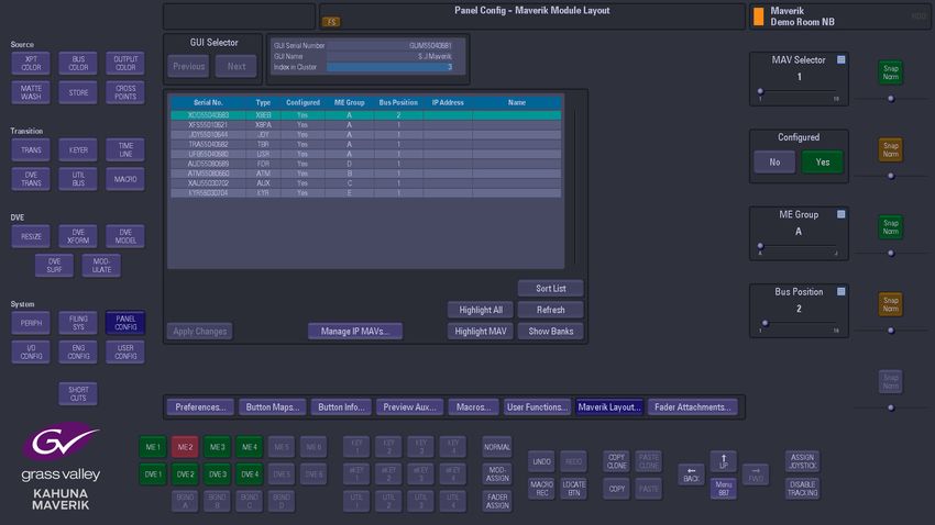
On the external GUI, touch the “Panel Config” button. In the Panel Config menu, touch the
“Maverik Layout” menu link button.
The Maverik Layout menu displays all the MAV modules connected to the mainframe for
the selected cluster.
To setup the MEG module, touch the “Manage IP MAVs” button. This will open the IP MAV
Address Configuration menu, this is where you enter the IP address of the MEG module.
Touch the “Create/Edit” button and using the IP Address dialog box, enter the IP address of
the MEG module and touch “Apply”
11Kahuna MEG
Setting up the MEG module with Kahuna
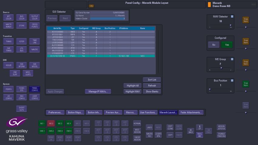
Touch the “IP MAV Setup” button and you will see that the MEG module has been added to
the system. The information contained in the list is the serial number of the MEG module
and the IP address.
Go back to the “Maverik Layout” menu by touching the “Up” button and you will see the
MEG module listed in the table (as shown below). You now have to use the “ME Group”
parameter to give the MEG a group letter and use the “Bus Position” parameter to give
MEG a Bus position number. Once this is done, set the “Configured” parameter to “Yes”.
Finally touch the “Apply Changes” button.
The MEG module is now setup ready to use.
Note: If the MEG module is unplugged from the external PSU or PoE and
then plugged back in, it will take approx 30 seconds to re-establish itself to
the Kahuna system.
12Contact Us
Grass Valley Technical Support
For technical assistance, contact our international support center, at
1-800-547-8949 (US and Canada) or +1 530 478 4148.
To obtain a local phone number for the support center nearest you, please consult the
Contact Us section of Grass Valley’s website (www.grassvalley.com).
An online form for e-mail contact is also available from the website.
Corporate Head Office
Grass Valley
3499 Douglas-B.-Floreani
St-Laurent, Quebec H4S 2C6
Canada
Telephone: +1 514 333 1772
Fax: +1 514 333 9828
www.grassvalley.comYou can also read