LABORATORY INCUBATORS MODELS: TI-150F & TI-150G TI-250F & TI-250G TI-350F & TI-500F WITH OMRON E5CC CONTROL
←
→
Page content transcription
If your browser does not render page correctly, please read the page content below
LABORATORY INCUBATORS
         MODELS:
     TI-150F & TI-150G
     TI-250F & TI-250G
     TI-350F & TI-500F

WITH OMRON E5CC CONTROL

          Thermoline Scientific Equipment Pty. Ltd.
        T/A Thermoline Scientific ABN 80 000 859 129
   10-12 Ross Place. Wetherill Park. N.S.W. 2164. Australia.
P.O. Box 6862, Wetherill Park Delivery Centre, N.S.W. 1851. Australia.
        Phone: (02) 9604 3911. International: 61 2 9604 3911.
          Fax (02) 9725 1706. International: 61 2 9725 1706.
 Email: sales@thermoline.com.au        Web: www.thermoline.com.au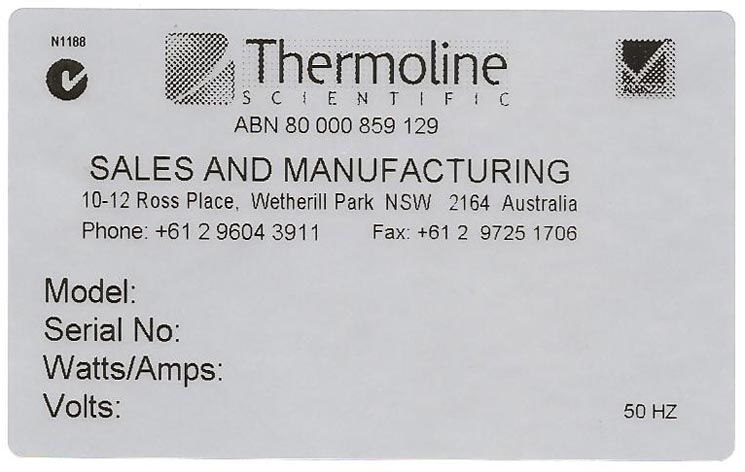
P age |2

                                       INTRODUCTION:

        Thank you for selecting this equipment from the large range of products manufactured
in Australia by Thermoline Scientific.
        This manual covers the operation, cleaning, & maintenance instructions for this
equipment. Incorrect operation or use can cause harm or damage to the equipment, therefore
it is very important that you read, understand, and implement the instructions, to ensure
reliable operation.
Please keep this manual in a safe place for future reference.

                                          CONTENTS
INTRODUCTION:                              2
UNPACKING:                                 2
USE & FUNCTION:                            2
LOCATION & INSTALLATION:                   3
LOCATION.
ELECTRICAL
SPECIFICATIONS.
PRINCIPLE OF OPERATION:                     3
CONTROL PANEL:                              4
OPERATION:                                  4&5
SENSOR CORRECTION:                          5&6
MAINTENANCE:                                6
CARING FOR STAINLESS STEEL.
TECHNICAL ASSISTANCE.
PRODUCT WARRANTY:                           7&8

                                         UNPACKING:
Remove the equipment from the packing material and check for damage. Notify the detail of
any damage to your supplier or to Thermoline Scientific without delay.
Retain the packing materials until the equipment has been thoroughly tested.

Inventory:
   • Shelves: TI-150F/G = 3 shelves, TI-250F/G = 4 shelves, TI-350F & TI-500F = 5 shelves.
   • Operating Instructions.
   • Electrical mains cable.

                                        USE & FUNCTION:
The Thermoline range of Premium Laboratory Incubators are designed and manufactured in
Australia to provide a reliable controlled temperature environment .They are suitable for use in
microbiology, immunology, culture departments, stability storage of veterinary samples,
education, and many more. They provide an economical, temperature controlled environment
with a temperature range up to 60ºC.

Features:
   • Four sizes ranging from 150 litres to 500 litres, two with gravity convection and four with
      forced air circulation for more accurate temperature uniformity.
   • Stainless steel liners (easy clean surface & non corrosive).
   • Fibreglass insulation for efficiency.
   • Digital temperature control with over temperature alarm.
   • Electronically controlled heating element pads.
26-1-16
P age |3

   •      Monitoring port hole.
   •      Removable chrome plate shelves.
   •      Insulated solid door closing on a magnetic gasket.
   •      Clear inner viewing door.

                                  LOCATION & INSTALLATION:

LOCATION:

Place the equipment in a well-ventilated area on a firm level surface, in a location that has a
stable ambient temperature.
Allow sufficient room for the door to open fully.

   1. These incubators are not suitable for use with flammable solvents! They are fitted
      with components that may be a source of ignition.
   2. The incubators are not suitable for stacking!
   3. The range of equipment described here are not to be used in conjunction with
      large quantities of water. The introduction of water and the resultant vapour could
      result in premature component failure.

ELECTRICAL:

This cabinet is suitable for connection to a standard 240 volt, 50Hz, supply. A dedicated outlet
should be used for the supply, do not use power boards or the like. A 3-pin moulded plug is
fitted as standard to the mains lead. A removable power lead plugs into the IEC socket at the
rear of the incubator.

SPECIFICATIONS:

Electrical: 240 volts, 50 HZ. TI-150G = 290 Watts. TI-150F = 310 Watts. TI-250G = 400 Watts.
TI-250F = 420 Watts, TI-350F = 470 Watts, TI-500F = 570 Watts.
Temperature Range: Ambient plus 5ºC to 60ºC.
Temperature Control Accuracy: +/- 0.25ºC

PRINCIPLE OF OPERATION

The range of incubators is all suitable to be floor mounted. The TI-150G/F can also be bench
mounted.
The case is insulated to minimise heat loss. The outer door which is also insulated closes on a
magnetic gasket.
Each shelf position has a removable chrome plated open wire shelf.
An inner clear door allows viewing of products for evaluation without unduly disturbing the
conditions inside the incubator.
Removable chrome plate open wire type shelves are supplied with extra shelf spacing.
The desired operating temperature is set at the temperature controller. Heater pads are
attached to the outside of the incubator walls to provide even temperature distribution. Air
movement is either gravity convection for “G” models, or fan forced for “F” models.
The temperature sensor provides an accurate measure of the temperature inside the
incubator.

26-1-16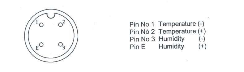
P age |4
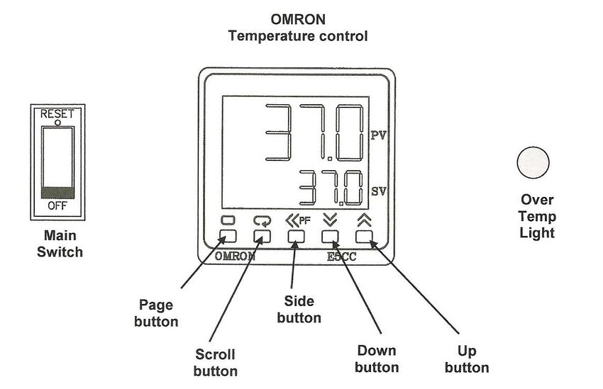
CONTROL PANEL:
Page button: Used to view calibration offset parameter.
Scroll button: Not used by the operator.
Side arrow: Used to move the cursor when changing temperature.
Down arrow: Used to decrease parameter setting.
Up arrow: Used to increase parameter setting.
OPERATION:
1. Locate the incubator as previously described in “Location”, plug the mains lead into the
IEC socket at the back of the case and into the power supply. Turn on the power point.
2. Turn on the main switch on the control panel. The switch is illuminated so you will know
when it is on. The temperature will go through a short warm up period where all
segments of the display will be on, before indicating the set temperature (SV) on the
lower display and oven temperature (PV) on the top display.
3. The Omron E5CC is a microprocessor based instrument that has been factory
configured for range, sensor type, and engineering parameters for optimum control.
Limited access to the control parameters is available. The operator can alter the
temperature set point and has access to a parameter used for calibration purposes.
26-1-16P age |5
4. TO CHANGE THE SET TEMPERATURE:
• Use the button to move the cursor, the digit will flash indicating that it can
be changed.
• Use the or arrows to change the temperature. When the desired
temperature is set leave for a few seconds and the digits will stop flashing to
confirm entry.
5. OVER TEMP LIGHT: The temperature control has been configured with automatic over
temperature alarm. In case of a malfunction the alarm will turn off all forms of heating
when the incubator temperature is more than 2ºC above the set temperature. In this
instance the red “over temp” alarm light will be illuminated.
6. DO NOT place any open water containers inside the incubator to increase
humidity levels. The interior of the incubator is not sealed and moisture may
penetrate the insulation layer which could lead to the heater pads failing.
SENSOR CORRECTION:
There are a number of factors that will affect the accuracy of the temperature displayed in
relation to the actual temperature inside the incubator, these include the following:
• Product load inside the incubator (product should be distributed evenly across each
shelf with space left for air flow between items).
• Control temperature (at higher temperatures the heat loss from the incubator will be
greater).
• Location of the sensor (the temperature sensor can never be placed in the centre of the
incubator because it could be damage).
Because of the above factors there may be an error between the temperature displayed and
the temperature measured at the middle of the incubator. For this reason the Omron
temperature control has a parameter that can be used to correct the temperature displayed.
This sensor correction parameter is displayed as .
In simple terms this parameter adds or subtracts a correction value to the displayed
temperature to make it read the correct temperature. The calibration parameter can be
accessed as follows:
• Prior to any calibration of the temperature display ensure that the equipment used to
measure the incubator temperature has a current certificate of calibration to a traceable
source, and that you are confident that it is accurate.
26-1-16P age |6
Press the page Use the up or Allow the digit to
button to access down arrow to stop flashing and
the sensor enter the sensor the screen will
correction correction value. display the adjusted
parameter. value.
In the example above the incubator temperature displayed (PV) is 37ºC. If a certified reference
instrument measured 36ºC we would need to correct the temperature by -1.0ºC (note that the
sensor correction parameter is accurate to 1 decimal place).
MAINTENANCE
The Thermoline Scientific incubators require no routine maintenance other than normal levels
of cleanliness.
The external surface powder coated steel and the inner surface and door stainless steel may
be wiped clean using a damp, soft cloth.
CARING FOR STAINLESS STEEL
Stainless steel is under most conditions extremely resistant to corrosion. This is in part due to
the addition of chromium and nickel to the steel and the formation of a durable chromium oxide
at the surface during the manufacturing process. There are several chemicals which will attack
the surface of stainless steel, plus the lack of oxygen at the surface will cause rusting,
corrosion and pitting. Note: Deionised water is particularly corrosive, to minimise, maintain a
Neutral pH (7-9).
Always have in place a program of regular cleaning using a soft damp cloth with a mild solution
of soap and water and allow to dry.
TECHNICAL ASSISTANCE
If you require additional operational or technical information regarding this equipment please contact:
Thermoline Scientific
Customer Service Division
Telephone: 61 2 9604 3911
Facsimile: 61 2 9725 1706
Email: thermoline@thermoline.com.au
26-1-16P age |7
WARRANTY:
Have the following information available when you contact the service department:
• Model number and serial number. This is generally found on the exterior of the cabinet
in the form of a stick-on label.
MODEL NO:
SERIAL NO:
• The company name, address, contact name, contact phone number.
• A brief description of the problem.
All warranty claims must be reported to, and agreed to by a Thermoline representative
prior to any work being carried out.
Retransmission Signal Connection (Optional): A socket is located on the side of the
cabinet for connection to an outside monitoring system, which is able to accept the 4-20mA
signals, representing 0.0 to 100.0°C and 0 to 100% RH. Maximum load to be applied to the
analogue output is 500 ohms.
Pin connections for retransmission socket:
26-1-16P age |8
Standard 12 month Warranty
Thermoline Scientific Equipment Pty Ltd ABN 80 000 859 129 (“Thermoline”)
Thermoline warrants to the original purchaser that this product will perform to its product specification for a period of 12 months
from date of purchase, provided that the installation of the product has been carried out in accordance with the latest version of the
manufacturer's instructions and further provided that the use of the product complies with that specified in the relevant specification.
Thermoline is not responsible for any loss or damage arising from incorrect usage, usage outside the suitability of the product as
stipulated in the manufacturer's instruction, damage caused by accident, fire, flood, act of God or failure to properly install, operate
or maintain the goods in accordance with the printed instructions provided.
The following statement applies only to product sales that fall within the definition of a Consumer Sale set out in the Australian
Consumer Law contained within the Competition and Consumer Act (Cth) 2012:
‘Our goods come with guarantees that cannot be excluded under the Australian Consumer Law. You are entitled to a replacement or
refund for a major failure and for compensation for any other reasonably foreseeable loss or damage. You are also entitled to
have the goods repaired or replaced if the goods fail to be of acceptable quality and the failure does not amount to a major failure.’
Notwithstanding the preceding clause and to the extent permissible by law, the liability of Thermoline is limited, in relation to the
warranted product and at the option of Thermoline to:
• replacing the product or the supply of equivalent product;
• the repair of the product;
• the payment of the cost of replacing the product or of acquiring equivalent product; or
• the payment of the cost of having the product repaired.
To the extent permitted by law, all other warranties whether implied or otherwise, not set out in this Warranty are excluded and Thermoline
is not liable in contract, tort (including, without limitation, negligence or breach of statutory duty) or otherwise to compensate the Purchaser
for:
• any increased costs or expenses;
• calibration/certification services;
• any loss of profit, revenue, business, contracts or anticipated savings;
• any loss or expense resulting from a claim by a third party; or
• any special, indirect or consequential loss or damage of any nature whatsoever caused by Thermoline’s failure in complying with
its obligations or the purchaser’s failure due to accident damage, impact, misuse or negligence.
The benefits given to the purchaser in this Warranty are in addition to other rights and remedies under a law in relation to the
products or services to which this warranty applies.
This warranty applies only to products purchased and installed in Australia and does not cover any consumable items e.g. filters, light
globes, ultrasonic nebulizers. The warranty does not extend to labour and freight costs where the warranted product is located
outside Australia.
To make a warranty claim, contact Thermoline on 02 9604 3911 or service@thermoline.com.au.
26-1-16You can also read