LGB 2x212 Stainz en Conversion with a 4 pin - Massoth
←
→
Page content transcription
If your browser does not render page correctly, please read the page content below
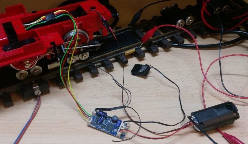
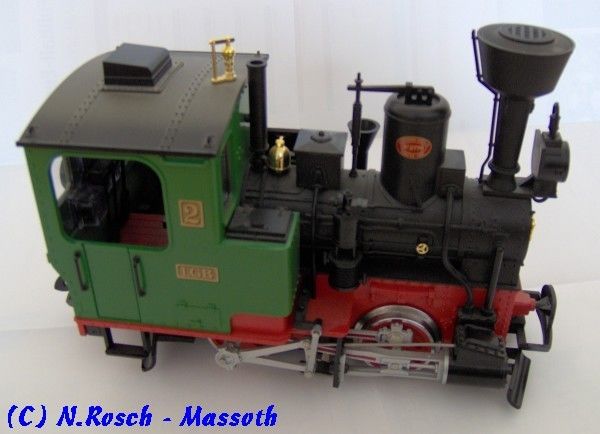
Umbaubericht
Lokomotiven

LGB 2x212 Stainz en
Conversion with a 4 pin gearbox

Backfitting plan of a “Stainz” with a 4-pin D-Gear, with an eMotion LS Sounddecoder. (Pict 1)
This loco have 1 headlight front and rear, interior lighting, a smoke generator and a simple analogue
sound.
The existing main board with interface will be completely removed during these renovations, while
we need this place for the decoder.
The old sound will be shut down by disconnecting.

Pict-1: LGB-20212 Stainz
Needed parts:
1x 8211100 LS-Sounddecoder Steam loco
1x 8312108 Micro cable set (thereof 1x 2pol. for Speaker)
1x 8104010 PCB and Decoder Brackets (1 piece from 10piece Set)
1x 8151601 eMOTION Powercap micro (Recommendation for outdoor layouts)

Stand 15.04.2020                                                                            Seite 1 / 18
Umbaubericht
Lokomotiven

Conversion:
     • Disassemble loco (Remove 2 bolts on the coupling blocks at the bottom and 2 screws for the
       upper rod holder.)
     • Remove Gear.
     • Remove 4 screws for the cabin and the nut at the smoke stack.
     • Open boiler
     • Unscrew the lead weight in the boiler and remove PCB.
     • Modify lead weight for the fixing of the PCB and Decoder Bracket.

Pict-2: Mounting decoder
     • Open 4 screws at roof and take sound PCB.
     • Cut wires between speaker and PCB and solder the speaker cable (Pict 4) You can
       completely remove the switch.

Stand 15.04.2020                                                                         Seite 2 / 18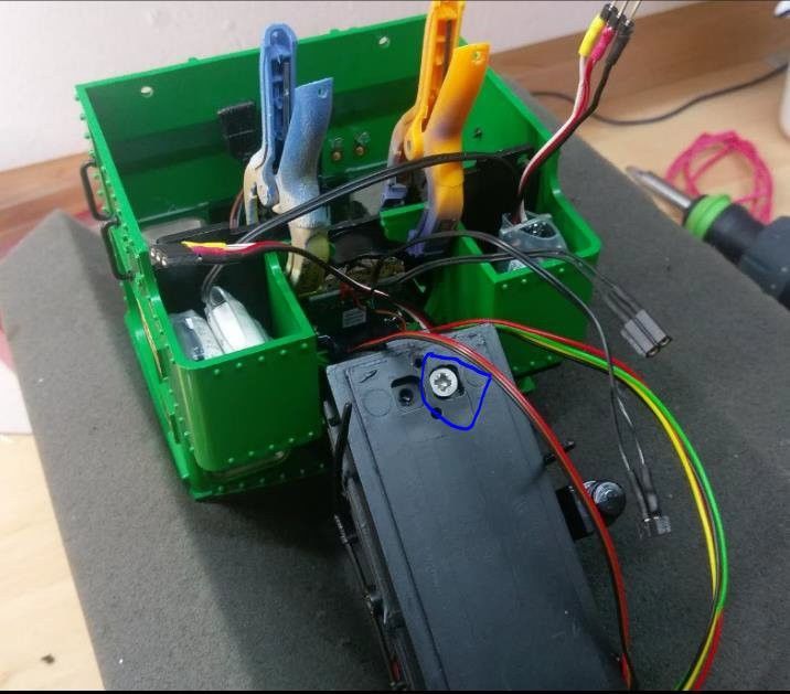
Umbaubericht
Lokomotiven

Pict-3: Speaker connection
     •   Solder the light-front cable to the 4pin light cable of LS. (Pict 3)
     •   Solder at Pin1 from light-rear the 4pin light cable of LS. (Bild 3)
     •   Remove the cable of interior light and solder it also to the 4pin light cable of LS. (Bild 3)
     •   You can connect both additional cables from light rear (plug) to track voltage.
     •   Snap the decoder in the bracket and put the 4 gear cables to bottom side.

Stainz-a4.jpg
Pict-4: Mounting light and smoke generator
     •   Connect light, F1 and speaker cable to the LS decoder.
     •   Solder smoke generator to the 3pin F1 cable of LS decoder (Pict 3)
     •   Check now your loco if all works fine.
     •   Reassemble loco completely in reverse order.

Additional hints:
     • Illumination and smoker are 19V, so you should reduce the voltage. The lamps in the Stainz
       are much too bright. (CV50 = appr. 20 tos 25 and CV53 = appr. 90)
     • At this backfitting we used the original LGB speaker. You can replace it with a better one to
       improve the sound.
     • We recommend to install a voltage buffer. While the buffer is to large, you have to take it in
       the cabin. Connect it like the manual to the 3 solder pins of the bottom side of the LS
       decoder (GND = black, +24V = red, BC = white). Maybe you can camouflage the buffer
       with coal bag dummies.

Stand 15.04.2020                                                                                 Seite 3 / 18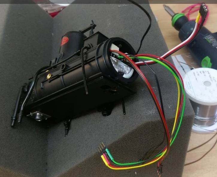
Umbaubericht
Lokomotiven

Conversion with half-shell gearbox

Conversion of a “Stainz” with half-shell gear.
An eMotion LS sound decoder is installed.
The locomotive has 1 headlamp in front, 1 headlamp in the back and 1 interior light.
Needed parts:
1x 8211100 LS-Sound decoder Steam loco
1x 8241050 28mm Visaton Speaker
1x 8104010 PCB and decoder bracket (1 piece of a 10 pcs set)
Conversion:
     • Disassemble the locomotive (remove 2 screws each on the coupling blocks on the ground
       and 2 screws for the rod holder).
     • Remove the gear unit.
     • Gearbox Conversion : Conversion Plans for Garden Rail Locomotives / Basics : Digital
       Gearboxes
     • Remove 4 screws for the driver’s cab and the nut at the bottom of the chimney.
     • Remove the lead weight from the boiler.
     • Machining the lead weight for the PCB holder

Picture-2: Installation of the decoder
     • Remove the standing boiler and create holes for the sound outlet of the loudspeaker. (For
       optical reasons, only small holes were drilled. This is sufficient for a medium volume
       behaviour with this locomotive. If you want it louder, just drill bigger holes.
     • As sound capsule or recording for the 28mm loudspeaker an old cap of a coke bottle is
       suitable.

Stand 15.04.2020                                                                           Seite 4 / 18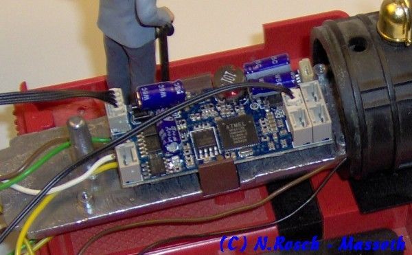
Umbaubericht
Lokomotiven

Picture-3: Installation of the loudspeaker
     • Solder the light front, light inside + light rear cable to the 4-pin light cable of the LS.

Picture-4: Light connection
     • Before final assembly, the locomotive should now be tested in advance
     • Reassemble the locomotive completely.

Further information:
     • Since the lighting is designed for 19V, the voltages should be slightly lower.
reduce. Besides, the lights on the Stainz are way too bright anyway. (CV50 = 25)
     • It is recommended to additionally install the voltage buffer. Since it is quite large, it must be
       placed in the driver’s cab. The connection is made on the underside of the LS decoder to the

Stand 15.04.2020                                                                                 Seite 5 / 18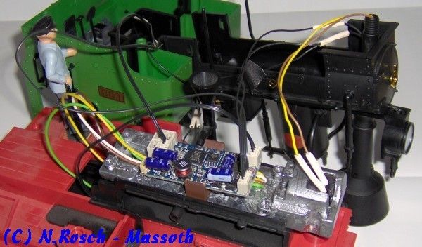
Umbaubericht
Lokomotiven

        3 solder connections (GND = black, +24V = red, BC = white). It may be possible to
        camouflage the buffer with coal bags.

LGB Stainz Retrofit with Pulsed Smoker for round Boilers, Massoth LS
Decoder, Powercap Micro and Firebox Light Module

This manual was kindly provided by Heiko Funk.
The essential changes are described here.
The installation of the firebox, in addition to the chic optical effect, fulfills the more important task
of supplying the pulsed smoke unit with sufficient air through the open door.
Cylinder steam is also possible, but then about 100 g weight must be dispensed with.
Needed parts:
1x 8415001 Pulsed Smoker for round Boilers
1x 8242060 eMOTION Firebox light module
1x 8242030 eMOTION Pulse generator (Soundaxle with thread) (If required, clock simulation is
also possible)
1x 8211100 LS-Sounddecoder Steam loco
1x 8104010 PCB & Decoder Brackets (1 pcs from 10 pcs Set)
1x 8151001 Powercap micro (Needed for Outdoor)
2x Bass reflex boxes or the Stainz set with speakers in the driver’s cabin
1x Brass tube 8 x 0,5mm, approx. 60 mm long (Depending on the chimney)
The locomotive will be disassembled as described in the link.
Retrofit:
The boiler door with fire
After removing the back of the boiler, an imprint was taken with kneading silicone.
Then pour out this mold with resin.
The boiler door should be milled and the door is glued open.

Stand 15.04.2020                                                                                 Seite 6 / 18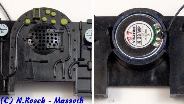
Umbaubericht
Lokomotiven

Still a little black silk-matte and finished.
The firebox light module is prepared according to instructions (aluminum foil and cable).
Round up a little the upper corners of the module so that the module as far as possible comes up.
Then stick it from behind in the wall.

Stand 15.04.2020                                                                            Seite 7 / 18
Umbaubericht
Lokomotiven

Weight shift
The pulsed smoker is built into the boiler instead of the lead weight.
This requires a shortening of the original weight to approx. 55mm.
The driving characteristics of the Stainz are ensured by their weight.
Weight is necessary here, every gram counts, so shift as lead into the front gearbox.
For this purpose, an imprint (kneading silicone) was produced, a plaster mold was produced and
poured out with lead, this weight is then fitted into the front.
This weighs about 100 gr.

The 8mm hole is used for the mounting of the boiler and must be re-drilled if it has not been spilled.

If the locomotive should be equipped with cylinder steam, the weight have to be remove.
Then you have to drill 5mm holes for the front of the gearbox, the chassis, the rail clearing and the
holder of the steam cylinders.

Stand 15.04.2020                                                                              Seite 8 / 18
Umbaubericht
Lokomotiven

Fitting the boiler
This part varies according to Stainz!
Angle a Z-shaped strip of aluminum sheet (about 1 mm thick 15 mm wide) like seen on the photo.
Glue the M6 drive-in nut like seen on the photo in the stripe, then glue the strip with 2-component
glue in the boiler.
It is important that the nut is seated inside the recess.

Stand 15.04.2020                                                                            Seite 9 / 18
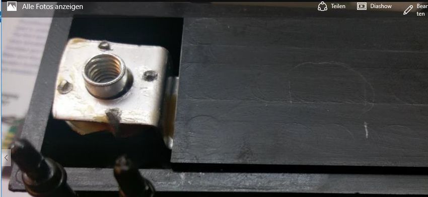
Umbaubericht
Lokomotiven

The drive-in nut must be located centrally in the hole of the chimney in the chassis base.

Stand 15.04.2020                                                                             Seite 10 / 18
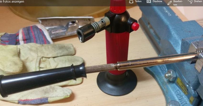
Umbaubericht
Lokomotiven

The chimney
In the Stainz various chimneys have been installed depending on the year of construction.
In the case of the chimneys without a smoke unit, the metal rods are poured into the plastic parts.
Since the plastic part is reused, a careful removal with a small Bunsen burner is necessary.

Cover the plastic with a very damp cloth.
Then heat the metal shaft about 5 cm to the right of the plastic, the flame away from the plastic.
Carry out the heating at intervals and check whether the plastic can be peeled off.
The shaft of the cobble chimney is toothed and much heavier to pull off.
In the smoke unit chimneys, it is sufficient to pull the shaft out of the chimney.
The plastic part is then drilled to 8 mm.
The 8mm pipe is pressed into this hole.
The length depends on the used Stainz.
The pipe should not extend into the enhanced area in the chimney.

Stand 15.04.2020                                                                             Seite 11 / 18
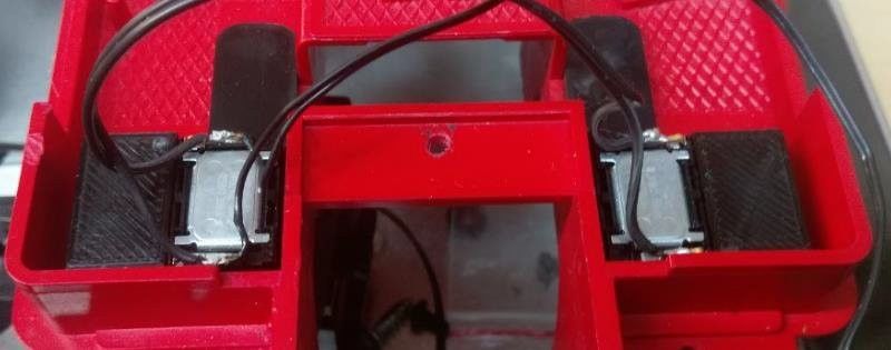
Umbaubericht
Lokomotiven

The 8mm tube can then be plugged into the pulsed smoke unit.

The speaker
There are various solutions, ranging from the box in the roof of the cab to the installation in the
boiler door.
The boiler door is not available (air supply), the box in the roof is for optical reasons no alternative.
With mobile phone speakers you have more possibilities.
In this case the total resistance of the loudspeakers of 8 Ohm must be observed!

Stand 15.04.2020                                                                                Seite 12 / 18
Umbaubericht
Lokomotiven

The speakers are glued with hot glue, openings upwards, in the bottom of the coal box.
Cable salad
This part of the conversion is the simplest.
All connections must be made according to the instructions of the components.
Special attention should be paid to this:
     •   The CVs of the programming block (CV15,CV16)
     •   The sequence of programming - first pulsed smoker, then decoder separate from each other
     •   Set the pulsed smoker to the Massoth Hall sensor
     •   Connect the firebox module to A2
     •   Programming the F keys appropriately (individually different)
The coal shuffeling is sound 8 and is set to F12 by default
The coal shuffeling sound was placed on F2 (the brake squeal on F12)
The firebox is only lit when the sound is played.

Stand 15.04.2020                                                                         Seite 13 / 18
Umbaubericht Lokomotiven The routing of the cables is well described in the manual by Norbert Rosch. In addition, this has been installed with a connector between chassis and boiler, which make subsequent revision extremely easy. Assembly Since now a few cables more than in the series, are present, it takes place. As always, the decoder finds its place on the shortened weight. The following cutouts must be made on the housing: Stand 15.04.2020 Seite 14 / 18
Umbaubericht
Lokomotiven

The cables are pulled later by the two-sided milled in the chassis.
The separation of the driver’s cab facilitates assembly.
For this purpose, the boiler rear wall is glued to the cab.
The PowerCap components are glued with hot glue into the coal boxes.
The decoder in the boiler, with the cables for: Powercap, loudspeaker, light, clock and engine block.

Stand 15.04.2020                                                                           Seite 15 / 18
Umbaubericht
Lokomotiven

The cables only as long as necessary, they must later fit between engine block and boiler lower part!

Stand 15.04.2020                                                                           Seite 16 / 18
Umbaubericht
Lokomotiven

The screw in the blue circle holds the lead weight in the boiler.
To the left is another.
When assembling on the chassis, place the cables in the milled sections and check whether they are
mobile.
Make the connections to the engine block and carefully push the engine block into the chassis.
Be sure to check the position of the cables and connectors.
Nothing should be squeezed.
Fasten the engine block (5x 3 mm screws), then screw an M6x60 countersunk screw into the drive-
in nut (do not forget the coupler ear) and fix the boiler.
Carefully push the chimney through the lamp holder into the boiler and evaporator.
It is sufficient if it protrudes approximately 3mm into the smoke unit.

Stand 15.04.2020                                                                          Seite 17 / 18
Umbaubericht
Lokomotiven

Have fun with a special Stainz!

Stand 15.04.2020                  Seite 18 / 18
You can also read