Managing Transmission Line Ratings - Federal Energy ...
←
→
Page content transcription
If your browser does not render page correctly, please read the page content below
20190823-4002 FERC PDF (Unofficial) 08/23/2019

                    Managing Transmission
                       Line Ratings
                              A STAFF PAPER:
                        FEDERAL ENERGY REGULATORY
                              COMMISSION

                                          AUGUST 2019

                                 DOCKET NO. AD19-15-000

                                 For further information, please contact:
                                            Dillon Kolkmann
                                 Office of Energy Policy and Innovation
                                 Federal Energy Regulatory Commission
                                           888 First Street, NE
                                         Washington, DC 20426
                                              (202) 502‐8650
                                       Dillon.Kolkmann@ferc.gov
20190823-4002 FERC PDF (Unofficial) 08/23/2019

        Contents
              EXECUTIVE SUMMARY .................................................................................... 1
              1.       BACKGROUND ........................................................................................... 4
                   A. TRANSMISSION LINE RATING BASICS .......................................................... 4
                   B. COMMON APPROACHES TO TRANSMISSION LINE RATINGS ......................... 5
                     i. Static Ratings ............................................................................................... 6
                     ii.  Seasonal Ratings ...................................................................................... 7
                     iii. Ambient-Adjusted Ratings (AARs)............................................................ 7
                     iv. Dynamic Line Ratings (DLRs) ................................................................. 7
                   C. DYNAMIC LINE RATINGS TECHNOLOGY CONSIDERATIONS......................... 8
                     i. Line identification and sensor installation .................................................. 8
                     ii.  Data communication and analytics .......................................................... 9
                     iii. Computing and forecasting .................................................................... 10
                     iv. Validation ............................................................................................... 10
              2.     LINE RATING APPROACHES IN RTOS/ISOS .................................... 11
                   A. USE OF SEASONAL LINE RATINGS IN RTOS/ISOS ..................................... 12
                   B. USE OF AARS IN PJM AND ERCOT........................................................... 12
                   C. USE OF STATIC RATINGS IN LONG TERM PLANNING ................................. 13
              3.        DYNAMIC LINE RATING PILOT PROJECTS .................................... 14
              4.    ANALYSIS ................................................................................................... 17
                A. EVALUATION OF DYNAMIC LINE RATINGS AND AMBIENT-ADJUSTED
                RATINGS ............................................................................................................... 17
                  i. Benefits....................................................................................................... 17
                  ii.  Challenges .............................................................................................. 21
                B. DISCUSSION ON POTENTIAL IMPROVEMENTS TO MANAGING
                TRANSMISSION LINE RATINGS ............................................................................. 26
                  i. Implementing AARs.................................................................................... 27
                  ii.  Integrating DLRs into EMS .................................................................... 27
                  iii. Study of the most congested transmission lines ..................................... 28
                  iv. Transparency of transmission line rating methodologies ...................... 28

               The opinions and views expressed in this FERC staff paper do not necessarily
        represent those of the Federal Energy Regulatory Commission, its Chairman, or
        individual Commissioners, and are not binding on the Commission.
20190823-4002 FERC PDF (Unofficial) 08/23/2019
Executive Summary
Transmission line ratings are used by reliability coordinators, transmission system
operators, planning authorities, and transmission planners in reliability models and
market models to ensure that flows on transmission lines do not increase risks of
reliability events or damage to lines or equipment. The transmission line ratings directly
affect flows on electric power systems, and thus affect the price of electric power and the
reliability of the electric grid. These ratings are determined by transmission owners. It
appears that transmission owners sometimes set these ratings with few or no updates to
reflect changes in ambient conditions, and with limited transparency into both the
methodology and resulting rating. Improving the methods for determining thermal
transmission line ratings could reduce costs, increase efficiency, and provide reliability
benefits. This paper reviews various transmission line rating practices. These practices
along with potential improvements to managing transmission line ratings will be
discussed at the upcoming FERC staff-led technical conference to be held in September
2019 in Washington, DC. There will also be an opportunity to file post-technical
conference comments in this docket, Managing Transmission Line Ratings, Docket No.
AD19-15-000.
This paper draws on staff outreach, which included discussions with regional
transmission organizations/independent system operators (RTOs/ISOs), transmission
owners, and trade groups, as well as staff participation in a November 2017 Idaho
National Laboratory workshop. During outreach, FERC staff reviewed existing and
advanced approaches to transmission line ratings and discussed the potential adoption of
advanced approaches, and more efficient and reliable use of transmission assets.
This paper focuses on transmission line ratings that are based on the thermal limits
of transmission lines to assure that lines do not overheat. In determining thermal limits,
engineers balance environmental and physical design factors that contribute to line
heating and cooling, in order to prevent the line from overheating. Overheating can
damage a line or cause it to sag and create reliability and/or public safety concerns.
There is a spectrum of approaches to line ratings, across which the approaches are more
responsive or less responsive to changes in the relevant ambient weather conditions that
underpin the ratings. On the least dynamic end of the spectrum, “static line ratings” are
derived using conservative assumptions for ambient weather conditions. On the most
dynamic end of the spectrum, “dynamic line ratings” (DLRs) account for real-time
ambient conditions such as air temperature, wind conditions, and solar irradiance
120190823-4002 FERC PDF (Unofficial) 08/23/2019
intensity, among other things, and update ratings frequently (e.g., hourly or every 15
minutes).
Today, most RTOs/ISOs implement either static line ratings or “seasonal line
ratings,” as provided by transmission owners for use in reliability planning, operations
and market models.1 On the less dynamic end of the spectrum, seasonal line ratings are
similar to static line ratings, but transmission owners determine different line ratings for
different seasons (typically winter and summer), based on worst case assumptions for
each season. Using a more dynamic approach, the Electric Reliability Council of Texas
(ERCOT) and PJM implement “ambient-adjusted ratings” (AARs) which adjust
frequently based on local ambient air temperatures.2 Non-RTO/ISO transmission owners
generally implement seasonal line ratings.
Aside from these standard practices, there have been several pilot projects to test
the development and potential application of DLRs. For the most part, these DLRs have
not been deployed in real-time system or market operations.3
Drawing on the outreach discussed above, this staff paper:
1) Discusses and evaluates the spectrum of transmission line rating methodologies;
2) Describes current RTO/ISO practices;
1
The seven RTOs/ISOs in the United States are all registered by the North
American Electric Reliability Corporation (NERC) as balancing authorities, reliability
coordinators, planning authorities/coordinators and transmission service providers. All of
these registered functions use transmission line ratings for their respective reliability
models. The six FERC-jurisdictional RTOs/ISOs under sections 205 and 215 of the
Federal Power Act are: California Independent System Operator Corporation (CAISO),
ISO New England Inc. (ISO-NE), Midcontinent Independent System Operator, Inc.
(MISO), New York Independent System Operator, Inc. (NYISO), PJM Interconnection,
L.L.C. (PJM), Southwest Power Pool, Inc. (SPP).
2
MISO and SPP also can accommodate ambient-adjusted ratings in their real-time
models.
3
Researching projects involving dynamic line ratings is not a new concept. These
activities date back decades.
220190823-4002 FERC PDF (Unofficial) 08/23/2019
3) Highlights some prominent advanced transmission rating pilot projects; and
4) Presents potential improvements to managing transmission line ratings for
discussion at the FERC staff-led technical conference. These are:
a. Whether to require all transmission owners to implement AARs on their
lines;
b. Whether to require all RTOs/ISOs to implement software and
communications capabilities and standards to allow transmission owners to
flow DLR data directly into the RTO/ISO’s energy management systems
(EMS);
c. Whether transmission owners should study their most congested
transmission lines to assess whether DLRs would be cost effective; and
d. Whether to make line rating methodologies more transparent.
320190823-4002 FERC PDF (Unofficial) 08/23/2019
1. Background
In spring 2019, a FERC staff team conducted outreach to all FERC-jurisdictional
RTOs/ISOs, ERCOT,4 seven transmission owners, Potomac Economics (the market
monitor for MISO, NYISO, ISO-NE and ERCOT), and Working for Advanced
Transmission Technologies (WATT, a trade group representing manufacturers of
advanced transmission technologies). In addition, staff attended and presented at a
November 2017 technical workshop on DLRs at the Idaho National Laboratory.
This paper draws on this outreach to examine approaches to transmission line
rating and to present possible policy options to facilitate the adoption of more advanced
line rating methodologies in order to reduce costs and achieve increased efficiency in the
use of transmission assets without undermining reliability.5 Increased efficiency can
result in important economic benefits, such as lower costs, as well as reliability and
operational benefits. More advanced line rating methodologies, however, also present
challenges relating to DLR sensor management, forecasting, rating coordination, and
reliability, among other things.
A. Transmission Line Rating Basics
Transmission line ratings are used by reliability coordinators, transmission system
operators, planning authorities, and transmission planners in reliability models and
market models to ensure that flows on transmission lines do not increase risks of
reliability events or damage to lines or equipment.6 They can be expressed in terms of
either electrical current (measured in units of amps (A)) or power-carrying capacity
4
ERCOT is jurisdictional under section 215 of the Federal Power Act.
5
While this paper draws on FERC staff outreach, the views expressed may not
necessarily reflect the positions of the outreach entities. Any errors in the representation
of outreach entities’ positions are unintentional.
6
Some entities in this list of transmission line rating users have overlapping roles.
For example, an RTO/ISO is transmission system operator and a transmission system
operator may also be a NERC reliability coordinator.
420190823-4002 FERC PDF (Unofficial) 08/23/2019
(measured in units of megawatts (MW) or megavolt-amps (MVA)). In this paper, a
transmission line rating respects the most limiting applicable equipment rating of the
individual equipment associated with the line,7 and is based on the thermal limit.8
The electric current flowing through a transmission line heats the line due to the
line’s electrical resistance. Other conditions and phenomena can also tend to heat
transmission lines, particularly solar irradiance. Conversely, some conditions and
phenomena tend to cool transmission lines, particularly convective cooling from wind.
Thermal transmission line ratings are generally negatively correlated to ambient
temperature and solar irradiance intensity, but positively correlated with wind speeds.
Conductor temperatures further depend upon conductor material properties, conductor
diameters, and conductor surface conditions. Engineers consider these environmental
and physical design factors when establishing thermal limits of transmission lines.
B. Common Approaches to Transmission Line Ratings
To ensure that transmission line ratings used in the reliable planning and operation
of the bulk electric system (BES) are determined based on technically-sound principles,
the North American Electric Reliability Corporation (NERC) Reliability Standard FAC-
008-3 requires each transmission owner to have a documented methodology for
determining transmission line ratings. The standard affords flexibility on underlying
methodologies and assumptions, including how changing ambient conditions are used. In
practice, rating methodologies have evolved along a spectrum from fully static ratings
with no change in ambient condition assumptions for thermal limits on conductors (or
sometimes based on “nameplate ratings” for limiting transmission equipment) to nearly
7
Specifically, the NERC Glossary of Terms Used in Reliability Standards (NERC
Glossary) includes a transmission line in its definition for a facility (“A set of electrical
equipment that operates as a single Bulk Electric System Element (e.g., a line, a
generator, a shunt compensator, transformer, etc.)”) and defines a facility rating as: “The
maximum or minimum voltage, current, frequency, or real or reactive power flow
through a facility that does not violate the applicable equipment rating of any equipment
comprising the facility.”
8
Staff note that transmission lines can be limited by their thermal rating, a voltage
limit, or a stability limit. The advanced line rating approaches discussed in this paper
would directly affect only lines that are limited by a thermal rating.
520190823-4002 FERC PDF (Unofficial) 08/23/2019
“real-time” ratings where ambient condition assumptions are updated every hour or
multiple times an hour. Figure 1 shows this spectrum of line rating practices:
Figure 1: Common line rating methodologies on the spectrum from least
dynamic to most dynamic
Seasonal line Ambient-adjusted
rating rating (AAR)
Static line Dynamic line
rating rating (DLR)
Less Dynamic More Dynamic
During industry outreach, staff observed that the terms “AAR” and “DLR” were
not well defined and not always used in a consistent manner. For the purposes of this
paper and subsequent discussions in this docket, FERC staff uses the terms “static line
ratings,” “seasonal line ratings,” AARs, and DLRs in specific ways as defined below.
In each type of transmission line rating, ratings may depend on the limitations of
individual segments of the transmission line. And the limits on the individual line
segments may depend on different ambient condition assumptions.
i. Static Ratings
Static ratings are the least dynamic rating methodology, and are intended to reflect
ratings under the worst case ambient condition assumptions. Often, static ratings reflect a
manufacturer’s equipment “nameplate rating” reflecting such worst-case assumptions.
Static ratings are only updated when equipment is changed or ambient condition
assumptions are updated. Thus, static ratings may remain unchanged for years or
decades, or may never change at all during the lifetime of a transmission line. While the
assumptions used to inform static transmission line ratings vary by transmission owner,
one outreach participant, for example, indicated that its static ratings assumed an ambient
air temperature of 40 degrees Celsius (104 degrees Fahrenheit), wind speeds and
direction of 2 feet per second at a 90-degree wind-conductor angle, and clear atmospheric
with noontime sun intensity.
620190823-4002 FERC PDF (Unofficial) 08/23/2019
ii. Seasonal Ratings
Seasonal ratings are similar to static ratings but use a different set of ambient
condition assumptions for summer and winter. Summer ratings are commonly used from
May through October, and winter ratings are commonly used from November through
April. Seasonal ratings are the most commonly used ratings. Summer transmission line
ratings use conservative ambient temperature assumptions, and are often based on 95 or
100 degrees Fahrenheit. Winter ratings are often based on 32 degrees Fahrenheit.
iii. Ambient-Adjusted Ratings (AARs)
AAR transmission line ratings are more dynamic than static and seasonal ratings,
and their rating values change on a more frequent basis (e.g., daily, hourly, or every 15
minutes).
Ambient air temperature forecasting is critical to the use of AARs. Some
transmission owners or AAR/DLR vendors perform temperature forecasting using
relevant ambient air temperature data from online weather monitoring services (such as
the National Oceanic and Atmospheric Administration (NOAA)), and then use those
temperature forecasts to calculate updated line ratings. In ERCOT and PJM, AARs are
implemented using step functions where AAR line ratings exist for 5-degree temperature
blocks (5 degrees Fahrenheit for ERCOT and 5 degrees Celsius for PJM).
iv. Dynamic Line Ratings (DLRs)
Presently, DLRs are the most dynamic line rating methodology incorporating
ambient conditions such as local weather conditions, solar irradiance, and/or line tension,
photo-spatial sensors (e.g., LIDAR), and/or line sensors installed on or close to the
monitored line.9 DLR weather sensors can measure weather parameters such as ambient
temperature, precipitation, wind speed/direction, and solar irradiance intensity. DLR
photo-spatial sensors or line sensors may measure conductor parameters such as
temperature, tension, and conductor clearance. DLR determined ratings can be updated
frequently depending on the characteristics of the DLR monitoring equipment.
9
LIDAR, or Light Detection and Ranging, is a commonly used surveying
technique to measure distance to a target by illuminating the target with a laser and using
a sensor to measure reflected light.
720190823-4002 FERC PDF (Unofficial) 08/23/2019
As with AARs, weather forecasting over a reasonable period of time (e.g., one
hour or 15 minutes) is important with DLR systems to allow transmission operators to
more efficiently and reliably operate their systems. When employing DLRs, automatic
processing of sensor data translates monitored data into updated line ratings.
C. Dynamic Line Ratings Technology Considerations
The previous section provided introductory information on transmission line rating
methodologies. As background, this section presents a snapshot of important technical
information about how some transmission owners and RTOs/ISOs implement DLRs.
This section also discusses some of the key technical challenges related to implementing
DLRs, but which are not necessarily relevant to implementing AARs.
The Institute of Electrical and Electronics Engineers (IEEE) and the Council on
Large Electric Systems (CIGRE) standards establish the accepted methods for calculating
the thermal behavior of transmission lines based on the conductor properties and weather
conditions.10 Based on these standards, modern technologies work in a coordinated
manner to calculate and update transmission line ratings in real-time, and to communicate
these updates to transmission system operators. These technologies include remote
sensing, measurement, communication, data analytics, high-performance computing
(including cloud computing), networking, and automation (including artificial
intelligence). Implementing a DLR system requires the following steps: line
identification; sensor installation; data communication; data analytics; computing and
temperature forecasting; and, finally, validation. These implementation steps are
discussed in greater detail below.
i. Line identification and sensor installation
As a first implementation step, transmission owners and/or RTOs/ISOs identify
the transmission lines on which DLRs would be cost-effective. Use of DLRs is typically
10
See IEEE Standard 738-2012, “IEEE Standard for Calculating the Current-
Temperature Relationship of Bare Overhead Conductors,” 2012 (IEEE 738); and CIGRÉ
Technical Brochure 207, “Thermal Behavior of Overhead Conductors, Working Group
22.12,” 2002(CIGRÉ 207).
820190823-4002 FERC PDF (Unofficial) 08/23/2019
cost-effective on a subset of a transmission owner’s transmission lines. Transmission
lines that are not sufficiently congested, such that they do not sufficiently limit desired
market activity, may not benefit from DLRs. Similarly, transmission systems that are
constrained by voltage, stability, or substation limitations may not benefit from DLRs. In
addition to identifying the transmission lines that will benefit from DLRs, the
transmission owners must identify which specific line spans need to be monitored, and
whether ground-based or line-based sensors should be used, as discussed further below in
Section 4.B.ii.
Both ground-based and line-based sensor approaches to DLRs have their
advantages and disadvantages. Line-based conductor measurements provide more direct
and accurate data on line conditions than measurement of ambient weather conditions.
However, line-based measurements have limits to how they can be extrapolated to yield
reliable information on non-monitored line segments. Also, line-based sensors may
require transmission line outages to install and maintain. Ground-based sensors can be
easier to install and maintain, but are more vulnerable to physical tampering.
ii. Data communication and analytics
Once sensors are operational, as a next implementation step, their data are
typically collected at a data concentrator and/or managed by a Supervisory Control and
Data Acquisition (SCADA) system or EMS. Measurement data or information is
commonly collected from individual sensors or sensor stations using a cellular network,
but satellite, microwave, or radio networks are also possible. The choice of
communication medium and methods depends on location, amount of data, and required
data transmission rate. Also, DLR system reliability, physical and cyber security features
are important factors in complying with NERC Reliability Standards to ensure the
availability, integrity, and confidentiality of DLR systems and data. Relevant Reliability
Standards include the following:
FAC-008-3, Facility Ratings, Requirements R7 and R8;11
11
On June 7, 2019, in Docket RM19-7-000 (pending), NERC filed a petition to
retire certain requirements of various reliability standards, including Requirements R7
and R8 of Reliability Standard FAC-008-3, which require transmission and generator
920190823-4002 FERC PDF (Unofficial) 08/23/2019
CIP-002-5.1a, Cyber Security – BES Cyber System Categorization;
CIP-006-6, Cyber Security – Physical Security of BES Cyber Systems;
CIP-012-1, Cyber Security – Communications between Control Centers;12 and
CIP-014-1, Physical Security.
iii. Computing and forecasting
After the relevant data is collected, it is processed and translated (according to the
technical standards discussed above) into a line current-carrying capacity in amps (A),
which is further used to determine the transmission line’s power-carrying capacity in
MW. As mentioned earlier, forecasting of the relevant weather conditions and line
ratings over some operationally useful period (e.g., one hour or fifteen minutes) is
necessary for DLR implementation.
iv. Validation
The final implementation step is validation. Rating validation should detect data
anomalies, possibly utilizing sensitivities that can limit the change in weather data
parameters that in turn can change transmission line ratings, and automatically integrate
DLRs into the control room SCADA, EMS, and/or security constrained economic
dispatch (SCED) engine.13 This step ensures confidence in the resulting transmission line
ratings.
owners to provide facility ratings to reliability coordinators, transmission system
operators and other entities upon request.
12
On April 18, 2019, in Docket No. RM18-20-000 (pending), the Commission
issued a notice of proposed rulemaking to approve CIP-012-1 (Cybersecurity-
Communications between Control Centers) and to direct NERC to develop certain
modifications to require protections regarding the availability of communication links
and data communicated between bulk electric system control centers and, further, to
clarify the types of data that must be protected.
13
While exact SCED definitions vary, one representative definition is “an
algorithm capable of clearing, dispatching, and pricing Energy, Operating Reserve, Up
Ramp Capability, and Down Ramp Capability in a simultaneously co-optimized basis
that minimizes Production Costs and Operating Reserve Costs while enforcing multiple
1020190823-4002 FERC PDF (Unofficial) 08/23/2019
During outreach, multiple parties indicated that reliability and operational
complexity concerns have hampered DLR (and AAR) adoption. Specifically, they
expressed concern that inaccurate or unreliable line ratings could be communicated
directly to transmission system operators, who would then be burdened with determining
whether to rely upon the ratings. However, line rating and human factors engineering
experts that FERC staff spoke to during outreach argued that proper implementation can
address this concern. The human factors engineering experts contended that all data and
rating validation must be complete before a transmission system operator ever sees a
DLR or AAR rating, allowing the operator to have confidence in the accuracy of
DLR/AAR ratings. Engineers should ensure that the rating is appropriate for the current
operational horizon so that the transmission system operator does not have to second-
guess the rating. In this way, the human factors engineering experts asserted, a
transmission system operator’s use of DLRs or AARs should be similar to the use of
static ratings.
One difference between DLRs/AARs and static ratings, however, is that the DLRs
and AARs change across their forecasting periods. As such, transmission system
operators may need access to the future period’s rating forecasts, and/or be notified by
EMS if significant rating changes will take place.
2.Line Rating Approaches in RTOs/ISOs
Transmission owners in RTOs/ISOs use either seasonal ratings or AARs to
calculate thermal transmission line ratings. In CAISO, ISO-NE, MISO, NYISO, and
SPP, seasonal ratings are the norm.14 In ERCOT and PJM, AARs are used.
security constraints. The algorithm keeps the commitment of Resources fixed in the
dispatch. The model is described in Schedule 29.” MISO Open Access Transmission
Tariff, Module A.
14
MISO and SPP also can accommodate ambient-adjusted ratings in their real-
time models, but our understanding is that few participants currently use this
functionality.
1120190823-4002 FERC PDF (Unofficial) 08/23/2019
A. Use of Seasonal Line Ratings in RTOs/ISOs
Five RTOs/ISOs – CAISO, ISO-NE, MISO, NYISO and SPP – predominantly use
seasonal line ratings, but with important regional differences. Some RTOs/ISOs tend to
be more deferential to transmission owner-developed line ratings than others. Certain
RTOs/ISOs indicated that some transmission owners provide seasonal ratings in which
winter line ratings equal summer ratings. Partially at the request of their transmission
owners, both MISO and SPP have updated their EMS to automatically accept frequently
changing line ratings. In MISO and SPP, transmission owners can automatically update
transmission line ratings hourly in the real-time reliability and market models in addition
to updates to current day and day-ahead transmission line ratings.
Several of the RTOs/ISOs indicated that they used a process whereby the
RTO/ISO, on an ad hoc basis, could request real-time transmission line rating “uprates”
which, if available, could be granted by the transmission owner based on differences
between actual ambient air temperatures and seasonal line rating assumptions. They
indicated that such practices are used to manage conditions such as outages, congestion,
or possible reliability events. Frequency and timing of usage varies by RTO/ISO. One
RTO/ISO described uprates occurring only on congested lines in the summer. Uprates
may be limited to the real-time reliability and market models or specific load pockets,
depending on the RTO/ISO.
B. Use of AARs in PJM and ERCOT
PJM and ERCOT rate transmission lines using AAR methodologies with regional
variations. Both PJM and ERCOT use temperature-rating step functions to rate
transmission facilities. In the real-time market, using transmission owner-submitted
temperature-based line ratings, a PJM computer program selects transmission line ratings
based on temperature readings taken from local weather stations for 5 degree Celsius (9
degree Fahrenheit) temperature increments from zero to 40 degree Celsius (32 to 104
degree Fahrenheit). In the PJM day-ahead market, transmission line ratings are
determined from forecasted ambient air temperatures specific to each zone in its day-
ahead studies.
ERCOT has a similar practice, in which real-time transmission line ratings are
automatically updated based on temperature fluctuations according to temperature tables
provided by each transmission owner and which reside within the ERCOT network
1220190823-4002 FERC PDF (Unofficial) 08/23/2019
model.15 ERCOT temperature tables are stepwise functions for each 5 degree Fahrenheit
(2.8 degree Celsius) increment between 20 and 115 degree Fahrenheit (approx. −7 to 46
degree Celsius). Similar to PJM, for the day-ahead market, ERCOT obtains forecasted
temperatures for the next operating day, and uses transmission owner’s temperature
tables to obtain line ratings for its day-ahead studies.
C. Use of Static Ratings in Long Term Planning
Each RTO/ISO conducts long term transmission planning using seasonal static
ratings. None of the RTOs/ISOs consider using DLRs or AARs as an alternative to
building physical transmission.16 Outreach consensus suggests that both transmission
owners the RTOs/ISOs consider it important to plan transmission for summer and winter
peak loading conditions while using seasonal static ratings and believe that neither DLRs
nor AARs can substitute for building and repairing transmission lines. While Order No.
890-A held (and Order No. 1000 reiterated) the transmission planning process is
generally required to have comparable treatment for advanced technologies,17 neither
order provided specific guidance on how advanced technologies should be considered.
While some outreach participants acknowledged that the use of DLRs could replace some
economic projects (i.e., projects designed to reduce congestion costs rather than to
address a reliability need), these participants reiterated the need to plan for the worst case
conditions when planning transmission because worst case conditions do materialize.
15
ERCOT Nodal Protocols. Section 3.10.8 Dynamic Ratings. February 7, 2018,
available at http://www.ercot.com/mktrules/nprotocols/current.
16
This is also the norm outside of RTO/ISOs.
17
See Preventing Undue Discrimination and Preference in Transmission Service,
Order No. 890 at P 494, 118 FERC ¶ 61,119, order on reh’g, Order No. 890-A, 121
FERC ¶ 61,297, at P 215-16 (2007), order on reh’g, Order No. 890-B, 123 FERC 
61,299 (2008), order on reh’g, Order No. 890-C, 126 FERC ¶ 61,228, order on
clarification, Order No. 890-D, 129 FERC ¶ 61,126 (2009); Transmission Planning and
Cost Allocation by Transmission Owning and Operating Public Utilities, Order No. 1000,
FERC Stats. & Regs. ¶ 31,323, at P 315 (2011), order on reh’g, Order No. 1000-A, 139
FERC ¶ 61,132, order on reh’g and clarification, Order No. 1000-B, 141 FERC ¶ 61,044
(2012), aff’d sub nom. S.C. Pub. Serv. Auth. v. FERC, 762 F.3d 41 (D.C. Cir. 2014).
1320190823-4002 FERC PDF (Unofficial) 08/23/2019
3.Dynamic Line Rating Pilot Projects
Most of the seven transmission owners with whom FERC staff spoke indicated
that they had some experience using dynamic line ratings in research projects. However,
transmission owners typically test DLRs on only a few transmission lines, do not
incorporate DLRs into RTO/ISO markets, and do not publicize the test results widely.
Some prominent DLR pilots have been undertaken in ERCOT, NYISO, and PJM.
Two of the better documented and publicized DLR pilot projects were undertaken
by the ERCOT transmission owner, transmission operator, transmission planner and
distribution provider ONCOR, and by the NYISO generator owner, generator operator,
transmission planner and transmission owner New York Power Authority (NYPA), both
funded through grants under the Department of Energy’s Smart Grid Demonstration
Program. The NYPA project partnered with the Electric Power Research Institute (EPRI)
to install EPRI sensor technology designed to measure conductor temperature, weather
conditions, and conductor sag on three 230 kilovolt (kV) transmission lines. NYPA’s
goal was to test a variety of prototype technologies; demonstrate the viability for use in
system engineering, operations, and planning; and demonstrate a correlation between
increased dynamic ratings and increased wind generation. The results of the NYPA pilot
were calculations of DLRs, on average, in excess of 30 to 44 percent above static
ratings.18
Partnering with the cable and transmission line manufacturer Nexans, ONCOR
tested conductor tension-monitor technology along with conductor sag and clearance
monitors on eight transmission circuits (138 kV and 345 kV). Similar to NYPA,
ONCOR’s goals were to test the commercial viability of DLR technology. But ONCOR
also incorporated DLRs into real-time operations and developed a DLRs best practice
guide. ONCOR succeeded in incorporating DLRs directly into ERCOT’s EMS.
ONCOR’s project also identified the potential for DLRs to integrate wind resources,
18
Wang, Warren and Pinter, Sarah. Dynamic Line Rating Systems for
Transmission Lines. April 25, 2014 p. 36, available at
https://www.smartgrid.gov/files/SGDP_Transmission_DLR_Topical_Report_04-25-
14_FINAL.pdf.
1420190823-4002 FERC PDF (Unofficial) 08/23/2019
observing a relative increase in wind generation at the same times when DLR systems
increased study lines’ transmission capacities. Lastly, ONCOR calculated DLRs of, on
average, 30 to 70 percent greater than static line ratings. Relative to ERCOT’s normal
AARs, however, ONCOR observed real-time rating increases between only 6 and 14
percent on average (when excluding data anomalies, outage periods, and periods when
the DLR may have been lower than AARs).19
In PJM, DLR pilot studies were conducted on the 345 kV Cook-Olive
transmission line and on a second target transmission line.20 In the first phase of DLR
testing, LineVision, AEP, and PJM installed LineVision-designed ground-based sensors
to measure power flow, conductor position/sag, and weather conditions in order to
calculate DLRs along AEP’s Cook-Olive transmission line. The results of this first phase
indicated that Cook-Olive’s DLRs were significantly greater than static ratings.21
In phase two, LineVision, AEP, and PJM attempted to quantify the financial
impact of DLRs. To do this, LineVision, AEP, and PJM identified a target transmission
line similar to Cook-Olive, and which had already demonstrated DLR viability. The
target line was chosen because both it and Cook-Olive are high voltage transmission lines
of similar length (18 and 22 miles respectively), both are heavily congested, and both
have a straight transmission path, making DLR implementation easier.22
19
Id. at 59.
20
The Cook-Olive transmission line is located in the AEP footprint spanning
southwest Michigan to northern Indiana.
21
Marmillo, J, Mehraban, B, Murphy, S, and Pinney, N. A Non-Contact Sensing
Approach for the Measurement of Overhead Conductor Parameters and Dynamic Line
Ratings. CIGRE US National Committee 2017 Grid of the Future Symposium,
Cleveland, OH, available at
https://watttransmission.files.wordpress.com/2017/11/genscape-cigre-gotf-whitepaper-
2017.pdf.
22
Straight transmission paths can make DLR implementation easier by increasing
the consistency of the speed and direction at which the wind contacts a transmission line,
1520190823-4002 FERC PDF (Unofficial) 08/23/2019
Absent installing DLR sensors in phase two, LineVision, AEP, and PJM
extrapolated DLRs for the target line using weather data from NOAA at urban-center and
airport-based meteorological stations. To quantify the benefits, the study conducted an
analysis comparing a study year 2018 with static ratings to simulated market results using
DLRs on the target line. The analysis results demonstrated approximately $10.4 million
in annual congestion savings along the target line, but also found increased downstream
congestion on several nearby 230 kV lines, resulting in approximately $4 million in
annual net congestion savings. PJM explained that the analysis was not able to respect
other possibly limiting constraints, such as voltage constraints or substation-based
constraints. PJM indicated that a key drawback to its study is that the 2018 target line’s
limiting element was often set by substation equipment, not line limits.23 (For more
information on challenges created by other limiting elements see Section 4.A.ii.c).)
Other examples FERC staff encountered of transmission owners or RTOs/ISOs
implementing pilots or test DLRs indicated that these entities considered testing DLRs as
a means to mitigate the effects of transmission outages by increasing transmission line
limits. Separate entities described different DLR pilots implemented to improve
transmission access to a load pocket, to provide additional bridge transmission capacity
as transmission was built or rebuilt, and, one in the late 1990s, to alleviate congestion as
transmission upgrades were being built.
thus minimizing differing rating patterns across a transmission line. Straight transmission
paths can also make radio transmission of data easier, when relevant.
23
Dumitriu, N, Marmillo, J, Mehraban, B, Murphy, S, and Pinney, N. Simulating
the Economic Impact of a Dynamic Line Rating Project in a Regional Transmission
Operator (RTO) Environment. CIGRE US National Committee 2018 Grid of the Future
Symposium, Reston, VA, available at
https://cdn2.hubspot.net/hubfs/4412998/CIGRE%20GOTF%202018%20NGN%20-
%20PJM%20AEP%20LineVision%20-%20Final.pdf?t=1540927429509.
1620190823-4002 FERC PDF (Unofficial) 08/23/2019
4.Analysis
A. Evaluation of Dynamic Line Ratings and Ambient-
Adjusted Ratings
As a general matter, the more dynamic a transmission line rating, the more
accurate the line capacity and potential benefits, as well as challenges are expected from
its implementation. Outreach indicates that while the benefits of DLRs may be greater
than the benefits of AARs, the use of DLRs has greater challenges and costs. As
discussed below, some of the benefits and challenges accrue to both DLRs and AARs,
and some only to DLRs.
i. Benefits
a) Economic Benefits
Rating transmission lines more dynamically allows for adjusting line limits of
those lines, which have the potential to increase transmission system efficiency; reduce
production costs, congestion costs, curtailments, and reserve requirements; and help
manage system disturbances. Both DLRs and AARs tend to provide more accurate line
limits. Particularly in the summer season, this greater accuracy tends to raise
transmission line ratings, which has the potential to increase system efficiency.24 For
example, in MISO, Potomac Economics found that the potential savings as a result of
AARs reducing congestion costs would have been $165 million in 2015, $155 million in
2016, and $127 million in 2017.25 Similarly, increasing transmission flows into load
pockets can improve access for low cost generation, reduce curtailments, and may reduce
24
Staff notes, however, increased accuracy may not result in increased line ratings.
Particularly during the winter season, when real-time ambient air temperatures may be
greater than the static winter temperature assumption, line capacities under DLRs or
AARs may decrease from their seasonal ratings.
Potomac Economics. 2017 State of the Market Report for the MISO Electricity
25
Markets. June 2018. p. 83-84.
1720190823-4002 FERC PDF (Unofficial) 08/23/2019
reserve requirements. Lastly, in the event of a generation or transmission outage, both
DLRs and AARs may help mitigate the resulting congestion impacts.26
DLRs and AARs can potentially defer capital costs by improving utilization of
existing assets. Outreach participants indicated that, because transmission upgrades can
be difficult to build, DLRs are an important bridge source of transmission capacity in the
interim between the identification of need and project completion. Deferred capital costs
can be a benefit of AARs, but to a lesser degree.
DLRs (but not AARs) may also be particularly beneficial for transmission owners
integrating wind generation. When wind speed increases, this increases output from wind
generators. However, the increase in wind speed also lowers the temperature of the
transmission line which, under a DLR, would increase the rating of the line. This benefit
was demonstrated by the NYPA and ONCOR pilot projects discussed above.
Recognizing this correlation between wind production and lower transmission line
temperatures, at least one transmission owner suggested that a wind generator could
utilize DLRs to cost-effectively reduce the size of its interconnection facility. They
explained that interconnection studies typically use static line rating assumptions that
often have wind speed assumptions that are lower than is needed to power a wind turbine.
They suggested that, by conducting wind generator interconnection studies using higher
wind speed assumptions, it may be possible to increase wind power deliverability
assumptions and lower interconnection costs for wind generators, at least in some
circumstances.27
26
An important caveat repeatedly mentioned during outreach, however, was the
applicability of DLRs to older transmission lines. Outreach participants explained that
many of the most congested lines are older lines. Applying DLRs to such lines may have
short-term value, but such lines may be reaching the end of their useful life. In such
instances, it may be more cost-efficient to simply repair and/or rebuild the line.
However, repaired or rebuilt lines tend to not be congested. Even so, there may be value
to applying DLRs as a bridge to manage a transmission line while repairs occur.
27
Interconnection facilities are defined using the same definition as FERC Order
No. 2003, which explained that “Interconnection Facilities are found between the
Interconnection Customer's Generating Facility and the Transmission Provider's
Transmission System…Network Upgrades include only facilities at or beyond the point
1820190823-4002 FERC PDF (Unofficial) 08/23/2019
Some outreach participants, however, expressed skepticism regarding the
possibility of using DLRs to reduce interconnection costs for wind generation. The
interconnection process currently utilizes static line rating assumptions to determine
interconnection cost responsibilities. Transmission owners and RTOs/ISOs stress the
need to plan for worst case conditions. Outreach also indicates that wind developers
and/or their financing partners may be reluctant to make major generation investments
without building the full interconnection capacity to deliver the generation’s total output
to the system.
b) Reliability/Operational Benefits
DLRs and AARs can also provide reliability benefits by helping to avoid and/or
relieve transmission overloads without the need to re-dispatch, curtail transmission
service, shed load or reconfigure the system.
DLRs (but not AARs) can provide transmission owners more information about
the status of a transmission line. By using actual, real-time inputs, DLRs provide
reliability benefits by reflecting the actual current-carrying capabilities of the conductor
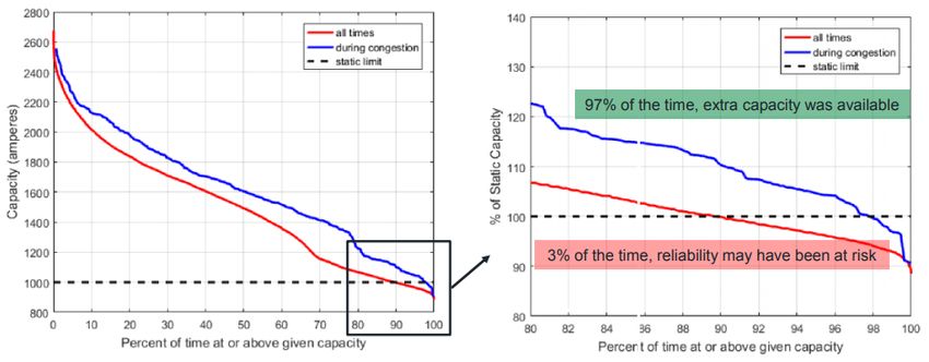
which may, at times, be less than a static rating would have allowed. Outreach
highlighted the ability of DLR systems to inform transmission owners and RTOs/ISOs of
the small percentage of instances in which static ratings exceeded a DLR, and in which
there may be a heightened risk of either a reliability event or damage to either
transmission lines or equipment. During outreach, one outreach participant estimated
that these instances where static ratings exceed DLRs could be up to five percent of
intervals, while data from LineVision presented at the 2017 Idaho National Laboratory’s
where the Interconnection Customer's Generating Facility interconnects to the
Transmission Provider's Transmission System.” See Standardization of Generator
Interconnection Agreements and Procedures, Order No. 2003, 104 FERC ¶ 61,103, at P
21 (2003), order on reh’g, Order No. 2003-A, 106 FERC ¶ 61,220, order on reh’g, Order
No. 2003-B, 109 FERC ¶ 61,287 (2004), order on reh’g, Order No. 2003-C, 111 FERC 
61,401 (2005), aff'd sub nom. Nat’l Ass’n of Regulatory Util. Comm’rs v. FERC, 475
F.3d 1277 (D.C. Cir. 2007), cert. denied, 552 U.S. 1230 (2008).
1920190823-4002 FERC PDF (Unofficial) 08/23/2019
2017 DLR workshop estimated that such instances constituted about three percent of
intervals, as shown in Figure 2.
Figure 2. Indicative Transmission Line Rating Static and Dynamic Line
Rating Duration Curve28
The additional information about a transmission line provided by DLRs can also
increase situational awareness, helping an RTO/ISO or transmission owner to monitor the
condition/health of a line in real-time. For example, in addition to informing an
RTO/ISO or transmission owner of instances in which the actual current-carrying
capabilities of the conductor is less than a static rating, such information gained through
increased situational awareness can allow an RTO/ISO or transmission owner to detect
dangerous instances of transmission icing and conductor galloping.29
28
Marmillo, Jonathan (2017, November). Genscape LineVision. Vision for
Integration into Overall Asset Management Strategy, Idaho National Laboratory 2017
Dynamic Line Ratings Workshop, Idaho Falls, Idaho. p. 8, available at
https://renewableenergy.inl.gov/Conventional%20Renewable%20Energy/2017%20DLR
%20Workshop/DLR%202017%20Presentations/11.8%20Vision%20for%20Integration%
20(Genscape)_Marmillo.pdf (used by permission).
29
Conductor galloping is a low-frequency physical oscillation of power lines
caused by wind. Galloping can lead to increases in stress on insulators and transmission
structures, increasing the risk of line or structure failure, or shortening equipment life.
Galloping can also affect line clearances, raising the risk of electrical faults. Some types
of DLR sensors can detect and/or monitor lines for galloping.
2020190823-4002 FERC PDF (Unofficial) 08/23/2019
c) Open Access Benefits
DLRs and AARs can also provide open access benefits, such as reducing the
likelihood of ad hoc transmission uprates, and thereby helping to ensure equal access to
the transmission system via markets on a comparable basis.30 Current releases of
additional transfer capability may lack the transparency that should be afforded to all
transmission customers. Upon RTO/ISO request, typically during periods of tight
operations, transmission owners periodically provide transmission uprates, temporarily
increasing transmission line limits. Generally, these transmission uprates help reliability.
Making these increases part of normal operations through the adoption of DLRs or AARs
on a transparent basis may help reduce the frequency of ad hoc transmission uprates.
While transmission uprates may frequently make available transmission capability in
real-time that was not reasonably foreseeable in advance, adoption of DLRs or AARs
could help ensure that all market participants are able to access the transmission system
on a comparable basis.
ii. Challenges
Many of the challenges to advanced line rating methodology implementation are
unique to DLRs. Challenges unique to DLR implementation relate to sensor placement,
sensor maintenance, and physical and cyber risks, as well as its tendency to cause line
rating fluctuations. By contrast, both DLRs and AARs face challenges related to
automation, coordination with other transmission owners, market coordination, limiting
elements, and reliability.
30
See Promoting Wholesale Competition Through Open Access Non-
Discriminatory Transmission Services by Public Utilities; Recovery of Stranded Costs by
Public Utilities and Transmitting Utilities, Order No. 888, FERC Stats. & Regs. ¶ 31,036
(1996) (cross-referenced at 77 FERC ¶ 61,080), order on reh’g, Order No. 888-A, FERC
Stats. & Regs. ¶ 31,048 (cross-referenced at 78 FERC ¶ 61,220), order on reh’g, Order
No. 888-B, 81 FERC ¶ 61,248 (1997), order on reh’g, Order No. 888-C, 82 FERC 
61,046 (1998), aff’d in relevant part sub nom. Transmission Access Policy Study Group
v. FERC, 225 F.3d 667 (D.C. Cir. 2000), aff’d sub nom. New York v. FERC, 535 U.S. 1
(2002).
2120190823-4002 FERC PDF (Unofficial) 08/23/2019
a) DLR Sensors
The most obvious challenges applicable only to DLRs are the placement and
maintenance of DLR sensors. First, sensor placement is a challenge because more
sensors are needed the longer a line is. But while placing more sensors at limiting
elements ensures more geographically-granular data to calculate line ratings at more line
spans, it costs more. While placing fewer sensors costs less, it requires the extrapolation
of data using complicated software and analysis to predict weather conditions, which can
be difficult or impractical. Extrapolating line conditions on monitored line spans to other
spans, particularly over varied terrain, can be difficult. Moreover, the more turns in a
transmission path and/or the more diverse the terrain a transmission line traverses, the
greater the number of sensors required and the more difficult it is to use one sensor to
extrapolate over multiple spans. Consequently, sensor placement challenges are often
more acute both with Midwestern utilities that tend to have longer transmission lines and
with utilities located in hilly, mountainous, or generally varied terrain.
Sensor maintenance can also be challenging. Repairs to DLR sensors often
require a specially trained technician. If a sensor is placed on a line, repairs may require
coordination between the transmission owner and a repair technician. Repairing line-
based sensors may also require a line to be taken out of service, which could necessitate
coordination between the transmission owner and the RTO/ISO. Further, ground-based
sensors can be susceptible to physical tampering that could either take them out of service
or create false data readings. Lastly, when transmitting DLR sensor data, there may be
potential cyber security risks.
b) Forecasting Challenges
Both DLRs and AARs require weather forecasting to be successfully
implemented. But because DLRs can be particularly sensitive to both wind speeds and
direction, forecasts for DLRs can be more difficult to produce. Swirling winds and
changing wind speeds can cause significant rating fluctuations that would be difficult for
transmission system operators to implement if such ratings were sent in raw form. In the
presence of hard-to-forecast wind conditions, DLR line rating forecasts may need to
assume that wind cooling cannot be relied upon. Under such assumptions, DLRs may
provide little benefit beyond what could be obtained with the simpler AARs.
2220190823-4002 FERC PDF (Unofficial) 08/23/2019
c) Limiting Elements
Physical limitations, other than those related to the transmission line conductor,
can reduce the benefits of DLRs and AARs. Because overall transmission line ratings
must be set by the most limiting element for each transmission line, substation equipment
(e.g., breaker, wave trap, or switch) limits could be a limiting element for a line
regardless of the effect of AARs or DLRs. For example, many wind generating facilities
are located at the top of hills and are connected by transmission lines running through
valleys. DLR implementation (but not AAR) would have to account for differing wind
conditions across the terrain, only increasing a transmission rating by the most limiting
wind condition, likely at the floor of a valley. Additionally, transmission owners
explained that many wind facilities, particularly in the Midwest, tend to be interconnected
via long transmission lines. Longer AC transmission lines tend to be voltage constrained,
not thermally constrained.
d) Automation and Data Coordination
Implementation of both DLRs and AARs requires automation and data
coordination. DLRs require at least automatic weather and/or line measurements, and
communication of that data to a transmission operator control center where that data is
used to calculate a rating forecast. AARs are typically derived by obtaining their ambient
air temperature data from NOAA or similar weather services, so measurement and data
communication are less of an issue. But under AARs, online data must still be
downloaded and used to calculate a rating forecast. As an example of the interaction
between data availability and AAR implementation, outreach indicated that the five week
U.S. Government shut-down of 2018-2019 resulted in limited data availability from
NOAA, which affected AAR implementation.
After collecting and communicating data and using that data to calculate updated
DLRs or AARs, several additional automation and data coordination challenges remain.
Calculated transmission line ratings must be automatically checked before being
transmitted to the RTO/ISO or transmission operator control center. Finally, the
transmission line ratings are input to a SCED and/or EMS, ideally automatically.
Most RTOs/ISOs indicated that automation of this kind is possible. However, due
to the additional costs and technological requirements, the amount of automation and
database management needed may be difficult for some non-RTO/ISO transmission
2320190823-4002 FERC PDF (Unofficial) 08/23/2019
owners to implement. Further, outreach indicated that this level of constant automation
and data coordination also creates a database management challenge.
e) Market Alignment
Some outreach participants expressed concern with using line ratings other than
static or seasonal ratings in the day-ahead market. They explained that if AAR or DLR
ratings were used in the day-ahead market, and weather was warmer than expected, the
anticipated transmission capacity may not materialize in real-time, while load would
simultaneously be higher than expected, causing reliability concerns. However, in such
instances, not implementing either AARs or DLRs in both the real-time and day-ahead
market might result in misalignments between day-ahead and real-time markets, creating
inefficiencies. Other outreach participants indicated that an appropriately conservative
implementation of AARs and/or DLRs could be made in the day-ahead timeframe in a
way that would help align the day-ahead and real-time markets, while still maintaining
reliability.
The use of AARs or DLRs in real-time and day-ahead markets could also result in
coordination challenges with the financial transmission rights (FTR) market.31 Static line
ratings are typically used to determine the amount of transmission capacity available for
auction in FTR and related auctions in RTOs/ISOs. The exception appears to be ERCOT,
which conducts a historical analysis of the maximum peak-hour temperatures for the
previous 10 years, for each month, to determine the amount of transmission capacity
available for auction in FTR auctions. In the two markets (ERCOT and PJM) that
31
While exact FTR definitions vary, one representative definition is “a financial
instrument that entitles the holder to receive compensation for or requires the holder to
pay certain congestion related transmission charges that arise when the Transmission
System is congested and differences in Marginal Congestion Components of Day-Ahead
Ex Post LMPs result.” MISO Open Access Transmission Tariff, Module A. FTRs go by
different names in different RTOs/ISOs. PJM, MISO and ISO-NE use the term FTR.
However, CAISO uses the term Congestion Revenue Right (CRR). NYISO uses the term
Transmission Congestion Contract (TCC). SPP uses the term Transmission Congestion
Right (TCR). For simplicity, this paper uses the term FTR to refer to the relevant product
in all these markets interchangeably.
24You can also read