Markerless and Efficient 26-DOF Hand Pose Recovery
←
→
Page content transcription
If your browser does not render page correctly, please read the page content below
Markerless and Efficient 26-DOF
                   Hand Pose Recovery

          Iasonas Oikonomidis, Nikolaos Kyriazis, and Antonis A. Argyros

                      Institute of Computer Science, FORTH
                                        and
                Computer Science Department, University of Crete
       {oikonom|kyriazis|argyros}@ics.forth.gr – http://www.ics.forth.gr/cvrl/

       Abstract. We present a novel method that, given a sequence of syn-
       chronized views of a human hand, recovers its 3D position, orientation
       and full articulation parameters. The adopted hand model is based on
       properly selected and assembled 3D geometric primitives. Hypothesized
       configurations/poses of the hand model are projected to different cam-
       era views and image features such as edge maps and hand silhouettes are
       computed. An objective function is then used to quantify the discrepancy
       between the predicted and the actual, observed features. The recovery of
       the 3D hand pose amounts to estimating the parameters that minimize
       this objective function which is performed using Particle Swarm Opti-
       mization. All the basic components of the method (feature extraction,
       objective function evaluation, optimization process) are inherently paral-
       lel. Thus, a GPU-based implementation achieves a speedup of two orders
       of magnitude over the case of CPU processing. Extensive experimental
       results demonstrate qualitatively and quantitatively that accurate 3D
       pose recovery of a hand can be achieved robustly at a rate that greatly
       outperforms the current state of the art.

1    Introduction
The problem of effectively recovering the pose (3D position and orientation) of human
body parts observed by one or more cameras is interesting because of its theoretical
importance and its diverse applications. The human visual system exhibits a remark-
able ability to infer the 3D body configurations of other humans. A wide range of
applications such as human-computer interfaces, etc, can be built provided that this
fundamental problem is robustly and efficiently solved [1]. Impressive motion capture
systems that employ visual markers [2] or other specialized hardware have been de-
veloped. However, there is intense interest in developing markereless computer-vision
based solutions, because they are non-invasive and, hopefully, cheaper than solutions
based on other technologies (e.g., electromagnetic tracking).
    The particular problem of 3D hand pose estimation is of special interest because by
understanding the configuration of human hands we are in a position to build systems
that may interpret human activities and understand important aspects of the interac-
tion of a human with her/his physical and social environment. Despite the significant
amount of work in the field, the problem remains open and presents several theo-
retical and practical challenges due to a number of cascading issues. Fundamentally,
2036    Iasonas Oikonomidis, Nikolaos Kyriazis, and Antonis A. Argyros

the kinematics of the human hand is complicated. Complicated kinematics is hard to
accurately represent and recover and also yields a search space of high dimensional-
ity. Extended self-occlusions further complicate the problem by generating incomplete
and/or ambiguous observations.

1.1    Related Work

A significant amount of literature has been devoted to the problem of pose recovery
of articulated objects using visual input. Moeslund et al [1] provide a thorough review
covering the general problem of visual human motion capture and analysis. The prob-
lems of recovering the pose of the human body and the human hand present similarities
such as the tree-like connectivity and the size variability of the articulated parts. How-
ever, a human hand usually has consistent appearance statistics (skin color), whereas
the appearance of humans is much more diverse because of clothing.
     A variety of methods have been proposed to capture human hand motion. Erol
et al [3] present a review of such methods. Based on the completeness of the output,
they differentiate between partial and full pose estimation methods, further dividing
the last class into appearance-based and model-based ones.
     Appearance-based methods estimate hand configurations from images directly after
having learnt the mapping from the image feature space to the hand configuration
space [4–7]. The mapping is highly nonlinear due to the variation of hand appearances
under different views. Further difficulties are posed by the requirement for collecting
large training data sets and the accuracy of pose estimation. On the positive side,
appearance based methods are usually fast, require only a single camera and have
been successfully employed for gesture recognition.
     Model-based approaches employ a 2D or 3D hand model [8–11]. In the case of 3D
hand models the hand pose is estimated by matching the projection of the model to
the observed image features. The task is then formulated as a search problem in a
high dimensional configuration space, which induces a high computational cost. Im-
portant issues to be addressed by such methods include the efficient construction of
realistic 3D hand models, the dimensionality reduction of the configuration space and
the development of techniques for fast and reliable hand posture estimation.
     This paper presents a novel, generative method that treats the 3D hand pose re-
covery problem as an optimization problem that is solved through Particle Swarm
Optimization (PSO). Under the taxonomy of [3], the present work can be categorized
as a full, model-based pose estimation method that employs a single hypothesis. The
method may integrate observations from an arbitrary number of available views with-
out requiring special markers. This is clearly demonstrated by our decision to consider
all free problem parameters jointly and simultaneously. As a direct consequence, con-
trary to the work of [10], our formulation of the problem allows for a clear and effortless
treatment of self-occlusions. PSO has been already applied for human pose recovery
in [12], however this is done in a hierarchical fashion in contrast to our joint optimiza-
tion approach. Additionally, the method of [12] is not directly applicable to hand pose
recovery because stronger occlusions must be handled given weaker observation cues.
     Being generative, the approach explores an essentially infinite configuration space.
Thus, the accuracy of estimated pose is not limited by the size and content of the
employed database, as e.g. in [7]. To the best of our knowledge, this is the first work
that demonstrates that PSO can be applied to the problem of 3D hand pose recovery
and solve it accurately and robustly. This is demonstrated in sequences with highly
Markerless and Efficient 26-DOF Hand Pose Recovery 2037
complex hand articulation where the hand is observed from relatively distant views.
Additionally, it is demonstrated that the careful selection of inherently data parallel
method components permits the efficient, near real-time 3D hand pose estimation and
gives rise to the fastest existing method for model-based hand pose recovery.
The rest of this paper is organized as follows. Section 2 describes in detail the pro-
posed method. Section 3 presents results from an extensive quantitative and qualitative
experimental evaluation of the proposed method. Finally, Sec. 4 summarizes the paper
by drawing the most important conclusions of this work.
2 Methodology
The proposed method can be summarized as follows. Observations of a human hand
are acquired from a static, pre-calibrated camera network. For each observation, skin
color detection and edge detection are performed to extract reference features. A 3D
model of a human hand is adopted that consists of a collection of parameterized geo-
metric primitives. Hand poses are represented by a total of 27 parameters that redun-
dantly encode the 26 degrees of freedom of the human hand. Given the hand model,
poses which would reproduce the observations are hypothesized. For each of them, the
corresponding skin and edge feature maps are generated and compared against their
reference counterparts. The discrepancy between a given pose and the actual obser-
vation is quantified by an error function which is minimized through Particle Swarm
Optimization (PSO). The pose for which this error function is minimal constitutes the
output of the proposed method at a given moment in time. Temporal continuity in
hand motion is assumed. Thus, the initial hypotheses for current time instance are
restricted in the vicinity of the solution for the previous time instant. The method
incorporates computationally expensive processes which cannot be adequately handled
by conventional CPU processing. However, the exploitation of the inherent data paral-
lelism of all the required components through a GPU powered implementation, results
in near real-time computational performance. The following sections describe in more
detail the components outlined above.
2.1 Observation Model
The proposed hand pose recovery method operates on sequences of synchronized views
acquired by intrinsically and extrinsically calibrated cameras. A set of images acquired
from a set of such cameras at the same moment in time is called a multiframe. If
Mi = {I1 , I2 , . . .} is a multiframe of a sequence S = {M1 , M2 , . . .} then Ij denotes the
image from the j-th camera/view at the i-th time step. In the single camera case, a
sequence of multiframes reduces to an image sequence.
An observation model similar to [10] is employed. For each image I of a multiframe
M , an edge map oe (I) is computed by means of Canny edge detection [13] and a
skin color map os (I) is computed using the skin color detection method employed
in [14]. As a convention, the label of 1 indicates presence and the label of 0 indicates
the absence of skin or edges in the corresponding maps. For each edge map oe (I), a
distance transform od (I) is computed. For each image I, maps O(I) = {os (I), od (I)}
constitute its observation cues.2038 Iasonas Oikonomidis, Nikolaos Kyriazis, and Antonis A. Argyros
Fig. 1: Hand model with colored parts. Each color denotes a different type of geometric
primitive (blue for elliptic cylinders, green for ellipsoids, yellow for spheres and red for
cones).
2.2 Hand Model
The model of hand kinematics used in this work is based on [15]. The kinematics of
each finger, including the thumb, is modeled using four parameters encoding angles.
More specifically, two are used for the base of the finger and two for the remaining
joints. Bounds on the values of each parameter are set based on anatomical studies
(see [15] and references therein). The global position of the hand is represented using
a fixed point on the palm. The global orientation is parameterized using the redun-
dant representation of quaternions. This parameterization results in a 26-DOF model
encoded in a vector of 27 parameters.
The hand consists of a palm and five fingers. The palm is modeled as an ellipsoid
cylinder and two ellipsoids for caps. Each finger consists of three cones and four spheres,
except for the thumb which consists of two cones and three spheres (see Fig. 1). All
required 3D shapes used in the adopted hand model consist of multiple instances of two
basic geometric primitives, a sphere and a truncated cylinder. These geometric primi-
tives, subjected to appropriate homogeneous transformations, yield a model similar to
that of [9]. Each transformation performs two different tasks. First, it appropriately
transforms primitives to more general quadrics and, second, it applies the required
kinematics. Using the shape transformation matrix
0 1
e · sx 0 0 0
B 0 e · sy 0 0 C
Ts = B@ 0
C, (1)
0 sz 0 A
0 0 1−e e
spheres can be transformed to ellipsoids and cylinders to elliptic cylinders or cones. In
Eq.(1), sx , sy and sz are scaling factors along the respective axes. The parameter e is
used only in the case of cones, representing the ratio of the small to the large radius of
the cone before scaling (if not transforming to a cone, e is fixed to 1). Having a rigid
transformation matrix Tk computed from the kinematics model, the final homogeneous
transformation T for each primitive (sphere or cylinder) is
T = Tk · Ts . (2)
A non-trivial implementation issue (see Sec. 2.5) is the correct computation of sur-
face normals. For given normals −
→
ni of the two primitives in use, and given homogeneousMarkerless and Efficient 26-DOF Hand Pose Recovery 2039
transformation T , the computation of the new surface normals − →
ni can be performed
−
→ −T −
→
according to [16] using the equation ni = (T )3×3 · ni . A3×3 denotes the upper-left
3 by 3 submatrix of A.
Having a parametric 3D model of a hand, the goal is to estimate the model param-
eters that are most compatible to the observed images/image features (Sec. 2.1). To
do so, we compute comparable image features from each hypothesized 3D hand pose
(see Sec. 2.5). More specifically, given a hand pose hypothesis h, an edge map re (h)
and a skin color map rs (h) can be generated my means of rendering. The reference
implementation of the rendering process is very similar to that of [9]. The informa-
tive comparison between each observation and corresponding hypotheses is detailed in
Sec. 2.3.
2.3 Hypothesis Evaluation
The proposed method is based on a measure quantifying how compatible a given 3D
hand pose is to the actual camera-based observations. More specifically, a distance
measure between a hand pose hypothesis h and the observations of multiframe M needs
to be established. This is performed by the computation of a function E(h, M ) which
measures the discrepancies between skin and edge maps computed in a multiframe and
the skin and edge maps that are rendered for a given hand pose hypothesis:
X
E(h, M ) = D(I, h, C(I)) + λk · kc(h). (3)
I∈M
In Eq.(3), h is the hand pose hypothesis, M is the corresponding observation multi-
frame, I is an image in M , C(I) is the set of camera calibration parameters correspond-
ing to image I and λk is a normalization factor. The function D of Eq.(3) is defined
as P P
os (I) ⊗ rs (h, c) od (I) · rs (h, c)
D(I, h, c) = P P +λ P , (4)
os (I) + rs (h, c) + re (h, c) +
where os (I), od (I), rs (h, c), re (h, c) are defined in Sec. 2.1. A small term is added to
the denominators of Eq.4) to avoid divisions by zero. The symbol ⊗ denotes the logical
XOR (exclusive disjunction) operator. Finally, λ is a constant normalization factor.
The sums are computed over entire feature maps. The function kc adds a penalty to
kinematically implausible hand configurations. Currently, only adjacent finger inter-
penetration is penalized. Therefore, kc is defined as
(
X −φ(p) φ(p) < 0
kc(h) = , (5)
p∈pairs
0 φ(p) ≥ 0
where pairs denotes the three pairs of adjacent fingers, excluding the thumb, and φ
denotes the difference between the abduction-adduction angles of those fingers. In all
experiments the values of λ and λk were both set to 10.
2.4 Particle Swarm Optimization
Particle Swarm Optimization (PSO) is an optimization technique that was introduced
by Kennedy et al [17]. It is an evolutionary algorithm since it incorporates concepts
such as populations, generations and rules of evolution for the atoms of the population
(particles). A population is essentially a set of particles which lie in the parameter2040 Iasonas Oikonomidis, Nikolaos Kyriazis, and Antonis A. Argyros
space of the objective function to be optimized. The particles evolve in runs which are
called generations according to a policy which emulates “social interaction”.
Canonical PSO, the simplest of PSO variants, was preferred among other optimiza-
tion techniques due to its simplicity and efficiency. More specifically, it only depends
on very few parameters, does not require extra information on the objective function
(e.g., its derivatives) and requires a relatively low number of evaluations of the objec-
tive function [18]. Following the notation introduced in [19], every particle holds its
current position (current candidate solution, set of parameters) in a vector xt and its
current velocity in a vector vt . Moreover, each particle i stores in vector pi the position
at which it achieved, up to the current generation t, the best value of the objective
function. Finally, the swarm as a whole, stores in vector pg the best position encoun-
tered across all particles of the swarm. pg is broadcasted to the entire swarm, so that
every particle is aware of the global optimum. The update equations that are applied
in every generation t to reestimate each particle’s velocity and position are
vt = K(vt−1 + c1 r1 (pi − xt−1 ) + c2 r2 (pg − xt−1 )) (6)
and
xt = xt−1 + vt , (7)
where K is a constant constriction factor [20]. In Eqs. (6), c1 is called the cognitive
component, c2 is termed the social component and r1 , r2 are random samples of a
uniform distribution in the range [0..1]. Finally, c1 + c2 > 4 must hold [20]. In all
performed experiments the values c1 = 2.8, c2 = 1.3 and K = ˛˛ √2 ˛ with
˛
˛2−ψ−2 ψ −4ψ ˛
ψ = c1 + c2 were used.
Typically, the particles are initialized at random positions and their velocities to
zero. Each dimension of the multidimensional parameter space is bounded in some
range. If, during the position update, a velocity component forces the particle to move
to a point outside the bounded search space, this component is zeroed and the particle
does not perform any move at the corresponding dimension. This is the only constraint
employed on velocities.
In this work, the search space is the 27-dimensional 3D hand pose parameter space,
the objective function to be minimized is E(M, h) (see Eq.(3)) and the population is a
set of candidate 3D hand poses hypothesized for a single multiframe. Thus the process
of tracking a hand pose requires the solution of a sequence of optimization problems,
one for each of the acquired multiframes. By exploiting temporal continuity, the solu-
tion over multiframe Mt is used to generate the initial population for the optimization
problem of Mt+1 . More specifically, the first member of the population href for Mt+1
is the solution for Mt ; The rest of the population consists of perturbations of href .
Since the variance of these perturbations depends on the image acquisition frame rate
and the anticipated jerkiness of the observed hand motion, it has been experimentally
determined in the reported experiments. The optimization for multiframe Mt+1 is exe-
cuted for a fixed amount of generations/iterations. After all generations have evolved,
the best hypotheses hbest is dubbed as the solution for time step t + 1.
2.5 Exploiting Parallelism
A reference implementation of the proposed method was developed in MATLAB. A
study of the computational requirements of the method components revealed that
PSO and skin color detection are very fast. The computations of edge maps and theirMarkerless and Efficient 26-DOF Hand Pose Recovery 2041
distance transforms are relatively slow but these tasks along with skin color detection
are only executed once per multiframe. The identified computational bottlenecks are
the rendering of a given 3D hand pose hypothesis and the subsequent evaluation of
Eq.(3). More specifically, the hand model consists of a series of quadrics for which ray
casting is used for rendering [9]. Additionally, since multiple quadrics overlap on the
projection plane, pixel overwriting will occur and z-buffering is required so as to produce
correct edge maps. The computation of Eq.(3) is a matter of pixel-wise multiplication
and summation over entire images. The whole process is computationally expensive and
prevents real-time performance. Reasonable PSO parameterizations where particles
and generations range in the orders of tens, correspond to more than 4 minutes of
processing time per multiframe.
GPU accelerated observation models have been employed in the past (e.g. [21]). In
contrast to previous work, we provide a detailed description of a GPU implementation
that exploits parallelism beyond the point of straightforward image processing and
rendering. Our GPU implementation targets the acceleration of the two performance
bottlenecks, i.e., rendering and evaluation. The rest of the tasks are also susceptible
to acceleration (e.g. [22–24]) but this was not considered in this work. The final im-
plementation used the Direct3D rendering pipeline to accelerate the computationally
demanding tasks and MATLAB to perform the rest of the tasks as well as overall task
coordination.
Rendering and evaluation of Eq.(3) are decomposed in three major GPU computa-
tion steps: geometry rendering, cue-map generation and cue-map reduction (see Fig. 2).
Multiple particles are evaluated in large batches instead of single particles. This de-
sign choice defines a fine parallelization granularity which makes GPUs the optimal
accelerator candidate.
Geometry rendering. The goal of the geometry rendering step is to simultaneously
render multiple hand hypotheses in a big tiled rendering. Multiple renderings, instead
of sequences of single renderings, were preferred in order to maximally occupy the
GPU cores with computational tasks. The non-trivial issues to address are geometry
instancing and multi-viewport clipping.
Hardware instancing [24] is used to perform multiple render batches efficiently. Ef-
ficiency regards both optimal GPU power exploitation and minimal memory usage.
Batch rendering of multiple hand configurations essentially amounts to rendering of
multiple instances of spheres and cylinders. However, the respective geometric instan-
tiations are not required to be explicit. Hardware geometry instancing can be used in
order to virtually replicate reusable geometry and thus make instantiation implicit.
A specialized pixel shader is used in order to perform custom multi-viewport clip-
ping. Multiple viewports are required to be simultaneously rendered. However, conven-
tional rendering pipelines do not account for multiple viewports, except for the case
of sequential renderings. Unless multi-viewport clipping was performed, out of bounds
geometry would expand beyond the tiles and spoil adjacent renderings.
The information that is transferred from CPU to GPU are the projection matrices
c for each tile and the view matrix T for each primitive. The output of this rendering is
the map rs (h, c), per pixel depth and per pixel normal vectors, encoded in four floating
point numbers.
Cue-map generation. During cue-map generation, the output of the geometry ren-
dering step is post-processed in order to provide cue-maps rs (h, c), re (h, c), os (I) ⊗ rs (h, c)2042 Iasonas Oikonomidis, Nikolaos Kyriazis, and Antonis A. Argyros Fig. 2: Back-projection error computation flowchart. Observations of a human hand and hypothesized 3D poses are compared. Reference features are extracted from mul- tiframes by means of skin color detection and edge detection. Artificial features are generated for the 3D pose hypotheses by means of rendering and edge detection. The three main GPU steps are annotated: geometry rendering, cue-map generation and cue-map reduction. and oe (I) · re (h, c) of Eq.(3). Cue-map rs (h, c) passes through this stage since it is computed during geometry rendering (see Fig. 2). Cue-map re (h, c) is computed by thresholding the discontinuity in normal vectors for a cross-neighborhood around each pixel. Cue-maps os (I) ⊗ rs (h, c) and oe (I) · re (h, c) are trivially computed by element wise operations between the operands. Cue-map reduction. In the cue-map reduction step, scale space pyramids are em- ployed to efficiently accumulate values across tiles. The expected input is an image that encodes maps rs (h, c), re (h, c), os (I) ⊗ rs (h, c) and oe (I) · re (h, c) and the ex- pected output is the sum over logical tiles of these maps. The pyramids are computed by means of sub-sampling, which is a very efficient GPU computation. Once the sums have been accumulated, the computation of Eq.(3) is straightforward.
Markerless and Efficient 26-DOF Hand Pose Recovery 2043
0.035 0.035 0.035 0.1
0.03 0.03 0.03
0.08
0.025 0.025 0.025
mean score
mean score
mean score
mean score
0.02 0.02 0.02 0.06
0.015 0.015 0.015 0.04
16 16
0.01 32 0.01 32 0.01
64 64 0.02
0.005 96 0.005 96 0.005
128 128
0 0 0 0
10 20 30 40 10 20 30 40 0 2 4 6 8 0 5 10 15
PSO generations PSO generations number of views noise percentage
(a) (c) (e) (g)
100 16 100 16 100 100
32 32
64 64
mean error (mm)
mean error (mm)
mean error (mm)
mean error (mm)
80 80 80 80
96 96
128 128
60 60 60 60
40 40 40 40
20 20 20 20
0 0 0 0
10 20 30 40 10 20 30 40 0 2 4 6 8 0 5 10 15
PSO generations PSO generations number of views noise percentage
(b) (d) (f) (h)
Fig. 3: Performance of the proposed method for different values of selected parameters.
In the plots of the top row, the vertical axis represents the mean score E. In the plots of
the bottom row, the vertical axis represents mean error in mm (see text for additional
details). (a),(b): Varying values of PSO particles and generations for 2 views. (c),(d):
Same as (a),(b) but for 8 views. (e),(f): Increasing number of views. (g),(h): Increasing
amounts of noise.
3 Experimental Evaluation
The quantitative and qualitative experimental validation of the proposed method was
performed based on both synthetic and real-world sequences of multiframes.
3.1 Quantitative Evaluation Based on Synthetic Data
The quantitative evaluation of the proposed method was based on synthetic sequences
of multiframes which make possible the assessment of the proposed method against
known ground truth. Towards this end, the hand model presented in Sec. 2.2 was
animated so as to perform motions as simple as waving and as complex as object
grasping. A synthetic sequence of 360 poses of the moving hand was created. Each pose
was observed by 8 virtual cameras surrounding the hand. This results in a sequence of
360 multiframes of 8 views, which constitute the input to the proposed method. The
required cue maps were synthesized through rendering (see Sec. 2.2).
The performed quantitative evaluation assessed the influence of several factors such
as PSO parameters, number of available views (i.e., multiframe size) and segmentation
noise, over the performance of the proposed method. Figure 3 illustrates the obtained
results. For each multiframe of the sequence, the best scoring hand pose hbest using
the specified parameter values was found. Figures 3(a), (c), (e) and (g) provide plots2044 Iasonas Oikonomidis, Nikolaos Kyriazis, and Antonis A. Argyros
of the score E(hbest , M ) (averaged for all multiframes M ) as a function of various
experimental conditions. Similarly, Figs. 3(b), (d), (f) and (h) illustrate the actual error
in 3D hand pose recovery in millimeters, in the experimental conditions of Figs. 3(a),
(c), (e) and (g), respectively. This error was computed as follows. The five fingertips as
well as the center of the palm were selected as reference points. For each such reference
point, the Euclidean distance between its estimated position and its ground truth
position was first calculated. These distances were averaged across all multiframes,
resulting in a single error value for the whole sequence.
Figures 3(a) and (b) show the behavior of the proposed method as a function of
the number of PSO generations and particles per generation. In this experiment, each
multiframe consisted of 2 views with no noise contamination. It can be verified that
varying the number of particles per generation does not affect considerably the error in
3D hand pose recovery. Thus, the number of generations appears to be more important
than the number of particles per generation. Additionally, it can be verified that the
accuracy gain for PSO parameterizations with more than 16 particles and more than 25
generations was insignificant. Figures 3(c), (d) are analogous to those of Figs 3(a),(b),
except the fact that each multiframe consisted of 8 (rather than 2) views. The error
variance is even smaller in this case as a consequence of the increased number of views
which provides richer observations and, thus, more constraints. The accuracy gain for
PSO parameterizations with more than 16 particles and more than 25 generations is
even less significant.
In order to assess the behavior of the method with respect to the number of avail-
able views of the scene, experiments with varying number of views were conducted.
Figures 3(e) and (f) show the behavior of the proposed method as a function of the
size of a multiframe. For the experiments with less than 8 views, these were selected
empirically so as to be as complementary as possible. More specifically, views with
large baselines and viewing directions close to vertical were preferred. In these experi-
ments, 128 PSO particles and 35 generations were used, and no segmentation noise was
introduced in the rendered skin and edge maps. The obtained results (Figs. 3(e) and
(f)) show that the performance improvement from one view to two views is significant.
Adding more views improves the results noticeably but not significantly.
In order to assess the tolerance of the method to different levels of segmentation
errors, all the rendered silhouette and edge maps were artificially corrupted with dif-
ferent levels of noise. The type of noise employed is similar to [7]. More specifically,
positions are randomly selected within a map and the labels of all pixels in a circular
neighborhood of a random radius are flipped. The aggregate measure of noise contami-
nation is the percentage of pixels with swapped labels. In the plots of Figs. 3(g) and (h),
the horizontal axis represents the percentage of noise-contaminated pixels in each skin
map. Edge maps were contaminated with one third of this percentage. The contami-
nation was applied independently to each artificial map rs and re . In this experiment,
128 PSO particles and 35 PSO generations were used, and multiframes of eight views
were considered.The plots indicate that the method exhibited robustness to moderate
amounts of noise and failed for large amounts of noise. The exhibited robustness can
be attributed to the large number of employed views. Since the noise of each view was
assumed to be independent from all other views, the emerged consensus (over skin
detection and edge detection) managed to cancel out low-variance noise. Figure 3 also
demonstrates that the design choices regarding the objective function E (Sec. 2.3) are
correct. This can be verified by the observed monotonic relation between E and the
actual 3D hand pose estimation error.Markerless and Efficient 26-DOF Hand Pose Recovery 2045
Table 1: Number of multiframes per second processed for a number of PSO generations
and camera views for 16/128 particles per generation.
Generations 2 views 4 views 8 views
10 7.69/2.48 4.22/1.26 2.14/0.63
15 7.09/1.91 3.65/0.97 1.85/0.49
20 6.23/1.55 3.19/0.79 1.62/0.39
25 5.53/1.31 2.85/0.67 1.44/0.33
30 5.00/1.13 2.59/0.57 1.30/0.29
35 4.55/1.00 2.34/0.50 1.18/0.25
40 4.18/0.89 2.15/0.45 1.09/0.23
Finally, Table 1 provides information on the runtime of these experiments. The
table shows the number of multiframes per second for various parameterizations of
the PSO (number of generations and number of particles per generation) and various
number of views. The entry in boldface corresponds to 20 generations, 16 particles
per generation and 2 views. According to the quantitative results presented earlier,
this setup corresponds to the best trade-off between accuracy of results, computational
performance and system complexity. This figure shows that the proposed method is
capable of accurately and efficiently recovering the 3D pose of a hand observed from a
stereo camera configuration at 6.2Hz. If 8 cameras are employed, the method delivers
poses at a rate of 1.6Hz.
3.2 Experiments with Real World Images
Real-world image sequences were acquired using a multicamera system which is in-
stalled around a 2 × 1m2 bench and consists of 8 Flea2 PointGrey cameras. Cameras
are synchronized by a timestamp-based software that utilizes a dedicated FireWire 2
interface (800 M Bits/sec) which guarantees a maximum of 125 μsec temporal discrep-
ancy in images with the same timestamp. Each camera has a maximum framerate of
30 f ps at highest (i.e. 1280 × 960) image resolution. The workstation where images are
gathered has a quad-core Intel i7 920 CPU, 6 GBs RAM and an Nvidia GTX 295 dual
GPU with 894 GF lops processing power and 896 MBs memory per GPU core.
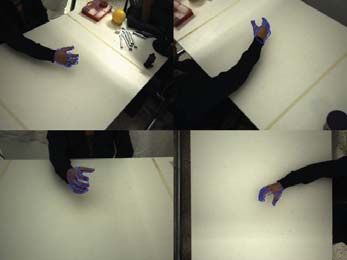
Several sequences of multiframes have been acquired, showing various types of
hand activities such as isolated motions and hand-environment interactions including
object grasping. Figure 4 provides indicative snapshots of 3D hand pose estimation
superimposed on the original image data. Videos with results of these experiments are
available online1 .
4 Discussion
In this paper, we proposed a novel method for the visual recovery of 3D hand pose of
a human hand. This is formulated as an optimization problem which is accurately and
robustly solved through Particle Swarm Optimization. In an effort to propose a method
that is both accurate and computationally efficient, appropriate design choices were
1
http://www.ics.forth.gr/∼argyros/research/3Dhandpose.htm.2046 Iasonas Oikonomidis, Nikolaos Kyriazis, and Antonis A. Argyros
Fig. 4: Sample frames from real-world experiments. Left: four views of a multiframe of
a cylindrical grasp. Right: Zoom on hands; Rows are from the same multiframe and
columns correspond to the same camera view.
made to select components that exhibit data parallelism which is exploited by a GPU
based implementation. The experimental evaluation in challenging datasets (complex
hand articulation, distant hand views) demonstrates that accurate pose recovery can
be achieved at a framerate that greatly outperforms the current state of the art. The
individual constituents of the proposed method are clearly separated. It is quite easy
for changes to be made to the objective function, the optimization method or the hand
model without affecting the other parts. Current research if focused on considering
more compact search spaces through the use of dimensionality reduction techniques.
Acknowledgements. This work was partially supported by the IST-FP7-IP-215821
project GRASP. The contributions of Asimina Kazakidi and Thomas Sarmis (members
of the CVRL/ICS/FORTH) are gratefully acknowledged.
References
1. Moeslund, T.B., Hilton, A., Krüger, V.: A survey of advances in vision-based
human motion capture and analysis. CVIU 104 (2006) 90–126
2. Wang, R.Y., Popović, J.: Real-time hand-tracking with a color glove. ACM Trans-
actions on Graphics 28 (2009) 1
3. Erol, A., Bebis, G., Nicolescu, M., Boyle, R.D., Twombly, X.: Vision-based hand
pose estimation: A review. CVIU 108 (2007) 52–73
4. Athitsos, V., Sclaroff, S.: Estimating 3d hand pose from a cluttered image. CVPR
2 (2003) 432
5. Rosales, R., Athitsos, V., Sigal, L., Sclaroff, S.: 3d hand pose reconstruction using
specialized mappings. In: ICCV. (2001) 378–385
6. Wu, Y., Huang, T.S.: View-independent recognition of hand postures. In: CVPR.
(2000) 88–94
7. Romero, J., Kjellstrom, H., Kragic, D.: Monocular real-time 3D articulated hand
pose estimation. IEEE-RAS Int’l Conf. on Humanoid Robots (2009) 87–92
8. Rehg, J.M., Kanade, T.: Visual tracking of high dof articulated structures: An
application to human hand tracking. In: ECCV, Springer-Verlag (1994) 35–46Markerless and Efficient 26-DOF Hand Pose Recovery 2047
9. Stenger, B., Mendonca, P., Cipolla, R.: Model-based 3D tracking of an articulated
hand. CVPR (2001) II–310–II–315
10. Sudderth, E., Mandel, M., Freeman, W., Willsky, A.: Visual hand tracking using
nonparametric belief propagation. In: CVPR Workshop. (2004) 189189
11. de la Gorce, M., Paragios, N., Fleet, D.: Model-based hand tracking with texture,
shading and self-occlusions. In: CVPR. (2008) 1–8
12. John, V., Trucco, E., Ivekovic, S.: Markerless human articulated tracking using
hierarchical particle swarm optimisation. Image and Vision Computing 28 (2010)
1530–1547
13. Canny, J.: A computational approach to edge detection. PAMI 8 (1986) 679–698
14. Argyros, A., Lourakis, M.: Real-time tracking of multiple skin-colored objects with
a possibly moving camera. In: ECCV. Volume 3., Springer (2004) 368–379
15. Albrecht, I., Haber, J., Seidel, H.: Construction and animation of anatomically
based human hand models. In: 2003 ACM SIGGRAPH/Eurographics symposium
on Computer Animation, Eurographics Association (2003) 109
16. Turkowski, K.: Transformations of surface normal vectors. Technical report, Tech.
Rep. 22, Apple Computer, July (1990)
17. Kennedy, J., Eberhart, R., Shi, Y.: Swarm intelligence. Morgan Kaufmann Pub-
lishers (2001)
18. Angeline, P.: Evolutionary optimization versus particle swarm optimization: Phi-
losophy and performance differences. Evolutionary Programming VII, LNCS 1447
(1998) 601–610
19. White, B., Shaw, M.: Automatically tuning background subtraction parameters
using particle swarm optimization. In: IEEE ICME. (2007) 1826–1829
20. Clerc, M., Kennedy, J.: The particle swarm - explosion, stability, and conver-
gence in a multidimensional complex space. IEEE Transactions on Evolutionary
Computation 6 (2002) 58–73
21. Shaheen, M., Gall, J., Strzodka, R., Gool, L.V., Seidel, H.P.: A comparison of
3d model-based tracking approaches for human motion capture in uncontrolled
environments. Workshop on Applications of Computer Vision (2009) 1–8
22. Luo, Y., Duraiswami, R.: Canny edge detection on NVIDIA CUDA. In:
CVPR’2008 Workshops. (2008) 1–8
23. Fischer, I., Gotsman, C.: Fast approximation of high-order Voronoi diagrams and
distance transforms on the GPU. Journal of Graphics, GPU, & Game Tools 11
(2006) 39–60
24. Pharr, M., Fernando, R.: Gpu gems 2: programming techniques for high-
performance graphics and general-purpose computation (2005)You can also read