MIC inteox 7100i - en Installation Manual
←
→
Page content transcription
If your browser does not render page correctly, please read the page content below

MIC inteox 7100i

en   Installation Manual


MIC inteox 7100i                                                                          Table of contents | en    3

Table of contents
1                        Safety                                                                                      4
1.1                      About this Manual                                                                           4
1.2                      Legal Information                                                                           4
1.3                      Safety Precautions                                                                          5
1.4                      Customer Support and Service                                                                7
2                        Introduction                                                                                8
2.1                      Parts List - Camera                                                                         8
2.2                      Additional Products Required                                                                8
2.3                      Additional Tools                                                                            9
2.4                      System requirements                                                                         9
2.5                      Establishing the connection                                                                 9
3                        Product Description                                                                       10
4                        Overview of Installation Steps                                                            11
5                        Mounting                                                                                  12
5.1                      Mounting Location and Orientation Options                                                 12
5.2                      Mounting Options                                                                          14
5.3                      Mounting Bracket Options                                                                  16
5.4                      Considerations for Mounting the Camera in Inverted Orientation                            17
6                        (Optional) Configuration Programming in the Shipping Box                                  19
7                        (Optional) Configuration Programming on a Temporary Table-top Stand                       20
8                        Installing a MIC Camera on a Hinged DCA                                                   21
9                        (Optional) Installing a Sunshield                                                         27
10                       (Optional) Installing the Illuminator                                                     30
11                       (Optional) Canting the Camera                                                             33
12                       Connection                                                                                38
12.1                     About Camera Power and Control                                                            38
12.2                     Power Source Options                                                                      38
12.3                     Ethernet Connections                                                                      39
12.4                     Camera Connections                                                                        40
13                       Troubleshooting                                                                           41
13.1                     Physical reset button                                                                     41
14                       Maintenance                                                                               42
14.1                     Replacing a wiper assembly                                                                43
15                       Decommissioning                                                                           51
15.1                     Transfer                                                                                  51
15.2                     Disposal                                                                                  51
16                       Technical data                                                                            52
17                       Best Practices for Outdoor Installation                                                   53
18                       Status Codes                                                                              55
19                       Support services and Bosch Academy                                                        60

Bosch Security Systems                                  Installation Manual                             2021-08 | 1.7 |

4      en | Safety                                                                                    MIC inteox 7100i

1                    Safety
1.1                  About this Manual
                     This manual has been compiled with great care and the information it contains has been
                     thoroughly verified. The text was complete and correct at the time of printing. Because of the
                     ongoing development of products, the content of the manual may change without notice.
                     Bosch Security Systems accepts no liability for damage resulting directly or indirectly from
                     faults, incompleteness, or discrepancies between the manual and the product described.

1.2                  Legal Information
                     Copyright
                     This manual is the intellectual property of Bosch Security Systems, and is protected by
                     copyright. All rights reserved.
                     Trademarks
                     All hardware and software product names used in this document are likely to be registered
                     trademarks and must be treated accordingly.

2021-08 | 1.7 |                                        Installation Manual                        Bosch Security Systems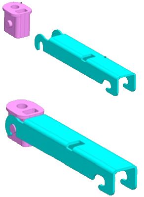
MIC inteox 7100i                                                                                             Safety | en     5

1.3                      Safety Precautions
                         In this manual, the following symbols and notations are used to draw attention to special
                         situations:

                         Danger!
                         High risk: This symbol indicates an imminently hazardous situation such as “Dangerous
                         Voltage” inside the product. If not avoided, this will result in an electrical shock, serious
                         bodily injury, or death.

                         Warning!
                         Medium risk: Indicates a potentially hazardous situation. If not avoided, this may result in
      !                  minor or moderate injury.

                         Caution!
                         Low risk: Indicates a potentially hazardous situation. If not avoided, this may result in
      !                  property damage or risk of damage to the unit.

                         Notice!

      i                  This symbol indicates information or a company policy that relates directly or indirectly to the
                         safety of personnel or protection of property.

Bosch Security Systems                                  Installation Manual                                      2021-08 | 1.7 |
6      en | Safety                             MIC inteox 7100i

2021-08 | 1.7 |      Installation Manual   Bosch Security Systems
MIC inteox 7100i                                                                                         Safety | en     7

1.4                      Customer Support and Service
                         If this unit needs service, contact the nearest Bosch Security Systems Service Center for
                         authorization to return and shipping instructions.
                         USA and Canada
                         Telephone: 800-289-0096, option 5
                         Fax: 800-366-1329
                         Email: repair@us.bosch.com
                         Customer Service
                         Telephone: 800-289-0096, option 3
                         Fax: 800-315-0470
                         Email: orders@us.bosch.com
                         Technical Support
                         Telephone: 800-289-0096, option 4
                         Fax: 800-315-0470
                         Email: technical.support@us.bosch.com
                         Europe, Middle East, Africa, and Asia Pacific Regions
                         Contact your local distributor or Bosch sales office. Use this link: https://
                         www.boschsecurity.com/xc/en/where-to-buy/
                         More Information
                         For more information, please contact the nearest Bosch Security Systems location or visit
                         www.boschsecurity.com.

Bosch Security Systems                                  Installation Manual                                  2021-08 | 1.7 |
8 en | Introduction MIC inteox 7100i
2 Introduction
– This equipment should be unpacked and handled with care. Check the exterior of the
packaging for visible damage. If an item appears to have been damaged in shipment,
notify the shipper immediately.
– Verify that all the parts listed in the Parts List below are included. If any items are
missing, notify your Sales or Customer Service Representative from Bosch Security
Systems.
– Do not use this product if any component appears to be damaged. Please contact Bosch
Security Systems in the event of damaged goods.
– The original packing carton (if undamaged) is the safest container in which to transport
the unit and must be used if returning the unit for service. Save it for possible future use.
Caution!
Take extra care lifting or moving MIC cameras because of their weight.
!
The MIC packaging is designed:
– to allow installers to configure the camera inside the shipping box.
– to provide a temporary table-top or desk-top stand.
2.1 Parts List - Camera
Quantity Component
1 MIC inteox 7100i camera
1 spanner tool [to remove and to attach the yoke caps in order to cant the
camera if desired, and to remove the access plug from the camera head
when installing the optional illuminator accessory (sold separately)]
1 base gasket
1 RJ45 coupler
1 MAC address labels
1 Quick Installation Guide
1 Safety instructions
2.2 Additional Products Required
Quantity Component
100 m Ethernet cable (Cat5e or better)
maximum
* Power cable (24 VAC)
* Alarm wiring as needed
* Audio wiring as needed
* Refer to the chapter Preparing Wiring.
2021-08 | 1.7 | Installation Manual Bosch Security SystemsMIC inteox 7100i Introduction | en 9
2.3 Additional Tools
1 Phillips-head screwdriver to secure the ground lug of the camera
1 Adjustable wrench or socket set to secure the base of the camera to mounting accessories
For canting cameras: 1 Torque wrench with a 5 mm Hex bit to remove/install bolts in the
yoke arms
2.4 System requirements
Our recommendations are:
– Computer with Dual core HyperThreading processor or better
– Graphic card with performance that matches or is better than the resolution of the
camera
– Windows 10
– Network access
– Google Chrome, Microsoft Edge, or Mozilla Firefox
- or -
Application software, for example, Video Security Client, Bosch Video Client or BVMS.
2.5 Establishing the connection
The unit must have a valid IP address and a compatible subnet mask to operate on your
network. By default, DHCP is pre-set at the factory to On and so your DHCP server assigns an
IP address. With no DHCP server the default address is 192.168.0.1
The Project Assistant app or Configuration Manager (version 7.50 or higher) can be used to
find the IP address. Download the software from https://downloadstore.boschsecurity.com:
1. Start the web browser.
2. Enter the IP address of the device as the URL.
3. During the initial installation, confirm any security questions that show.
Note:
If you cannot connect, the unit may have reached its maximum number of connections.
Depending on the device and network configuration, each unit can have up to 50 web browser
connections, or up to 100 connections via Bosch Video Client or BVMS.
Bosch Security Systems Installation Manual 2021-08 | 1.7 |10 en | Product Description MIC inteox 7100i
3 Product Description
The camera’s ruggedized design meets customer expectations in demanding environments
that exceed the capabilities of conventional IP cameras. Even in installations subject to harsh
shock/vibration conditions and/or extreme weather, the camera provides high-quality video
images.
– Make sure that the installation conditions comply with the specified stresses of vibration
and shock as mentioned in the datasheet.
A long-life silicone wiper blade mounted on a spring-loaded arm is standard on all MIC
cameras.
2021-08 | 1.7 | Installation Manual Bosch Security SystemsMIC inteox 7100i Overview of Installation Steps | en 11
4 Overview of Installation Steps
Caution!
Installation must be made by qualified personnel and conform to ANSI/NFPA 70 (the National
! Electrical Code® (NEC)), Canadian Electrical Code, Part I (also called CE Code or CSA C22.1),
and all applicable local codes. Bosch Security Systems accepts no liability for any damages or
losses caused by incorrect or improper installation.
Caution!
ELECTRIC SHOCK HAZARD
! To reduce the risk of electric shock, disconnect power to the camera and/or to the power
supply unit before moving the camera, before installing any accessories, and before mounting
the camera.
Before you install your MIC camera, inspect the camera for any scratches or damage to the
surface finish/paint. If you notice damage to the paint, return the unit for a replacement.
1. Select the Mounting Location and Orientation.
2. Install the appropriate 24 VAC power supply (VG4-A-PSU1 or VG4-A-PSU2) or midspan (60
W version or 95 W version). If you use the illuminator accessory, you must use the 95W
version.
Refer to the Installation Manual of the appropriate device for installation instructions.
3. Install grounded metal conduit (user-supplied) to the MIC DCA (sold separately) (and to the
PSU if necessary), install wiring (user-supplied), and then make the necessary connections for
power, telemetry, and video.
5. (Optional) Complete pre-configuration in the shipping box or on a table.
If installing the camera in inverted orientation, complete this step on a table-top stand only.
6. Install the DCA and then install the camera on the DCA.
OR
6. Install the camera directly to a mounting surface (such as an eave).
7. (Optional) Install the sunshield (sold separately).
8. (Optional) Install the illuminator (sold separately).
9. (Optional) Cant the camera.
10. Make the appropriate power and control connections.
Bosch Security Systems Installation Manual 2021-08 | 1.7 |12 en | Mounting MIC inteox 7100i
5 Mounting
5.1 Mounting Location and Orientation Options
Bosch designed MIC IP 7100i cameras for use in outdoor applications. In an enclosed
installation area (for example, in a foundry, near a furnace, etc.), temperatures outside of the
camera might exceed +65 °C (+149 °F). If you install a camera in an enclosed area, make sure
that the operating temperature of the camera is a maximum of +60 °C (+140 °F). Make sure
that air circulates around the camera to supply cooling.
MIC cameras are designed for easy installation in various locations such as directly onto
buildings and poles suitable to support CCTV equipment.
Select a secure installation location and mounting orientation for the device. Ideally, this is a
location where the device cannot be interfered with either intentionally or accidentally.
Select a location where the MIC camera will not touch materials such as steel straps or cables.
You can install the camera:
– onto a MIC-DCA or a MIC wall mount (MIC-WMB) with a MIC shallow conduit adapter
(MIC-SCA). (Never install the wall mount only.)
or
– directly to a mounting surface using the supplied base gasket and the appropriate
connector kit (sold separately):
– MIC-9K-IP67-5PK (IP67 Connector kit for MIC IP fusion 9000i, MIC IP ultra 7100i, and
MIC IP starlight 7100i cameras)
To have an installation rated IP67, you must use the appropriate IP67 Connector Kit from
Bosch.
Confirm that no residual water or moisture is in the bottom of camera. Ground the camera as
described in the chapter “Installing a MIC Camera on a Hinged DCA.”
You can install the camera in one of three orientations:
– upright (straight up, 90°)
– inverted (straight down, 90°)
– canted upright (tilted forward 35°)
The most common type of mounting location is the top of a pole suitable to support CCTV
equipment and that provides a robust mounting platform to minimize camera motion and
typically has a large base cabinet for mounting ancillary equipment such as power supplies.
Other locations for mounting the camera include the top of a building, the side (wall) of a
building, the corner of a building, and under the eave of a building.
The camera can also be mounted on the side of a lamp post, pole, or similar column using the
Pole Mount Bracket (MIC-PMB). Be aware that lamp posts can often be subject to movement
and are not suitable platforms in all conditions or for all applications.
Notice!
i Outdoor installation
For details about the proper configuration for installing your camera outdoors with surge and
lightning protection, refer to Best Practices for Outdoor Installation, page 53.
Ensure that the location has the appropriate clearance from power and lightning conductors,
in accordance with NEC725 and NEC800 (CEC Rule 16-224 and CEC Section 60).
Do not install the device near:
– Any heat sources
– Any overhead power lines, power circuits, or electrical lights, or where the device may
contact power lines, circuits, or lights
2021-08 | 1.7 | Installation Manual Bosch Security SystemsMIC inteox 7100i Mounting | en 13
Isolate shielded CAT5e or CAT6 cable from any high voltage power lines in a separate
grounded, metal conduit. Refer to the datasheet for test conditions for allowable transients /
voltage fluctuations.
Mounting surface recommendations for MIC mounting accessories
The mounting surface should be capable of supporting the combined weight of the MIC
camera + MIC Illuminator + MIC mounting accessory (DCA, wall mount, corner bracket, etc.).
All expected conditions of load, vibration and temperature should be considered when
planning an installation. The material should accommodate a minimum pull-out strength of 275
kg (600 lb).
The mounting accessory should be secured to one of the following surfaces:
– Concrete (solid / cast)
– Concrete masonry unit (concrete block)
– Brick (all types)
– Metal (steel / aluminum, minimum 3 mm (0.125 in.) thick)
In all situations, Bosch recommends referencing any applicable building codes or professional
structural engineering guidelines for a secure installation.
4 Ensure that the selected mounting surface is capable of supporting the combined weight
of the camera and mounting hardware (sold separately) under all expected conditions of
load, vibration, wind, and temperature.
Caution!
Risk of lightning strikes
If the camera is installed in a highly exposed location where lightning strikes may occur, then
Bosch recommends installing a separate lightning conductor within 0.5 m (1.6 ft) of the
! camera and at least 1.5 m (4.9 ft) higher than the camera. A good earth bonding connection
to the camera housing itself will provide protection against damage from secondary strikes.
The camera housing itself is constructed to cope with secondary strikes. If the correct
lightning protection is applied, then no damage to the internal electronics or camera should
result.
Installation in a damp environment (for example, near a coastline)
The fasteners and fixtures shipped with the camera help to keep the camera secure. Always
use Bosch-supplied screws and other fasteners when installing or performing maintenance on
the camera. Bosch-supplied hardware is properly treated and engineered for safe use with
your MIC camera.
The camera head has three (3) plastic screws, factory-installed, around each IR port to
prevent corrosion in units that do not have accessories installed on the camera head. If you
install a sunshield or an illuminator accessory, you must remove the plastic screws and
replace them with the metal screws that ship with each accessory.
Before installation, and periodically, inspect the metal parts of the camera for paint that is
chipped or otherwise damaged. If you notice any paint damage, return the unit for a
replacement.
Avoid installation practices that may bring the camera’s metal mountings in contact with
materials such as stainless steel. Such contacts can result in galvanic corrosion and degrade
the cosmetic appearance of the camera. These cosmetic damages caused by improper
installation are not covered by warranty as they do not affect the functionality of the camera.
Bosch Security Systems Installation Manual 2021-08 | 1.7 |14 en | Mounting MIC inteox 7100i
5.2 Mounting Options
See the figures that follow for illustrations of the correct and the incorrect mounting
orientations of MIC cameras.
MIC cameras are designed to be mounted upright (straight up, 90°), inverted (straight down,
90°), or canted upright (ball up, 35°). The tilt limits for the canted unit prevent it from working
properly if mounted ball down. See the figures below for illustrations of the correct and the
incorrect mounting orientations of MIC cameras.
Correct mounting orientation - upright, Correct mounting orientation - canted
inverted
Figure 5.1: Incorrect/not permitted mounting orientations (inverted + canted, horizontal)
2021-08 | 1.7 | Installation Manual Bosch Security SystemsMIC inteox 7100i Mounting | en 15
The figure below illustrates the tilt range of the camera in upright orientation.
90° 90°
55° 55°
Au
to
Pi
vo
t
Figure 5.2: Tilt range, MIC IP ultra 7100i
Bosch Security Systems Installation Manual 2021-08 | 1.7 |16 en | Mounting MIC inteox 7100i
5.3 Mounting Bracket Options
Bosch sells a complete series of mounting brackets that support multiple mounting
configurations.
Always use only Bosch-supplied mounts, which are designed for safe installation of your MIC
camera.
Refer to the MIC Series Mounting Brackets Installation Guide for complete installation
instructions.
Mounting hardware recommendations for MIC mounting accessories
Fasteners are not supplied with the MIC mounting accessories for attachment to the mounting
surface. The type of fastener necessary is dependent on the mounting surface.
Fasteners can include wedge anchors, sleeve anchors, single expansion anchors, double
expansion anchors, machine screws or ‘Thru-Bolting’ with a nut.
Fasteners are to be of a structural grade (ISO Class 10.9, SAE Grade 8) and zinc plated for
moderate corrosion resistance. When installed in marine or similarly corrosive environments,
stainless hardware (A2-800, A4-800) is recommended.
Fasteners are to be a minimum diameter of 8 mm (0.3125 in.).
All bolts must extend through the mounting surface and be secured with a flat washer, lock
washer and nut. All studs must be anchored to concrete or welded to a steel backing plate.
In all situations, Bosch recommends referencing any applicable building codes or professional
structural engineering guidelines for a secure installation.
Deep Conduit Adapter
The hinged DCA is well-suited to installations on top of a pole.
Wall Mount
MIC-SPR-BD,
-WD, -MG
MIC-SCA-BD,
-WD, -MG
MIC-WMB-BD,
-WD, -MG
Figure 5.3: Typical Wall mount configuration
Note: Always install an SCA when you install a wall mount for any installation configuration.
Route cables through the bottom of the SCA (to prevent water from running into the side or
top of the SCA along the cables).
Pole Mount
The figure below identifies the three mounting accessories (each sold separately) that are
necessary to mount the MIC camera on the side of a pole.
Note: The figure identifies the part numbers, as well as the codes for the available colors (-BD
for black, -WD for white, and -MG for grey) of each mounting accessory.
2021-08 | 1.7 | Installation Manual Bosch Security SystemsMIC inteox 7100i Mounting | en 17
MIC-WMB-BD,
-WD, -MG
MIC-SCA-BD,
-WD, -MG
MIC-PMB
Figure 5.4: Typical Pole mount configuration
Corner Mount
MIC-CMB-BD,
-WD, -MG
MIC-SCA-BD,
-WD, -MG
MIC-WMB-BD,
-WD, -MG
Figure 5.5: Typical Corner mount configuration
Note: Always install an SCA when you install a wall mount for any installation configuration.
Route cables through the bottom of the SCA (to prevent water from running into the side or
top of the SCA along the cables).
5.4 Considerations for Mounting the Camera in Inverted
Orientation
To change the camera orientation to “Inverted,” complete the following steps:
1. Remove the camera from the shipping box.
2. Apply power to the camera.
3. Access the web browser of the camera.
4. Access the page Configuration.
5. Navigate to Camera > Installer Menu > Orientation.
6. Select “Inverted.”
The camera head will rotate automatically into inverted position (180°).
Note the position of the visor when the camera is installed in inverted orientation. The visor
will now be near the body of the camera.
Bosch Security Systems Installation Manual 2021-08 | 1.7 |18 en | Mounting MIC inteox 7100i
Figure 5.6: MIC camera with camera head inverted
Note: It is not necessary to remove the section for the illuminator on the sunshield because
the illuminator is attached to the opposite side of the camera visor.
Seal the mount so that moisture or water cannot collect and stay in the bottom of the MIC
camera.
The figure that follows shows the camera installed in inverted orientation on a pole.
Figure 5.7: MIC camera mounted in inverted orientation (on pole)
2021-08 | 1.7 | Installation Manual Bosch Security SystemsMIC inteox 7100i (Optional) Configuration Programming in the Shipping Box | en 19
6 (Optional) Configuration Programming in the Shipping
Box
The camera packaging allows installers to connect the camera to the network and configure
the camera still in the box.
Caution!
Risk of damage to camera
Do not change the camera orientation to “Inverted” while the camera is still in the box. The
! camera head must be free to rotate. If you must change the camera’s orientation to
“Inverted,” remove the camera from the box and configure it by following the steps in
(Optional) Configuration Programming on a Temporary Table-top Stand.
1. Remove the packing material to access the camera’s electrical connectors.
2. Supply power to the camera and Connect the camera to the computer. Note that the wiper
moves one to three times across the camera window, and then returns to parked position.
3. Configure the camera. Refer to the separate User Manual for details.
4. Disconnect the wires/cables from the connectors in the base of the camera.
Refer to
– (Optional) Configuration Programming on a Temporary Table-top Stand, page 20
Bosch Security Systems Installation Manual 2021-08 | 1.7 |20 en | (Optional) Configuration Programming on a Temporary Table-top Stand MIC inteox 7100i
7 (Optional) Configuration Programming on a Temporary
Table-top Stand
Caution!
Take extra care lifting or moving MIC cameras because of their weight.
!
The camera (still in the foam) can stand temporarily on a flat, horizontal surface such as a
desk or a table during initial network connection and configuration.
1. Remove the packing material to access the camera’s electrical connectors.
1. Remove the foam covering the head of the camera.
3. Remove the camera, still in the foam, from the box. Place the camera upright on a flat,
horizontal surface.
1. Supply power to the camera and Connect the camera to the computer. Note that the
wiper moves one to three times across the camera window, and then returns to parked
position.
2. Configure the camera. Refer to the separate User Manual for details.
Notice!
If you change the camera orientation to “Inverted” (from the page Configuration of the web
i browser: Camera > Installer Menu > Orientation), then the camera head will rotate
automatically into inverted position (180°). Note that the visor will now be near the body of
the camera.
3. Disconnect the wires/cables from the connectors in the base of the camera.
2021-08 | 1.7 | Installation Manual Bosch Security SystemsMIC inteox 7100i Installing a MIC Camera on a Hinged DCA | en 21
8 Installing a MIC Camera on a Hinged DCA
The hinge feature allows installers to “hang” the camera temporarily but securely during
installation for easier connection of cables/wiring before final bolts are installed.
Parts List
Quantity Component
1 MIC Hinged DCA (MIC-DCA-Hx)
4 Stainless steel hex bolts, M8 x 30
4 Stainless steel plain washers, M8
1 O-ring, 80 mm x 3 mm
1 conduit adapter (male M25 to female 3/4" NPT) (Available in specific regions
only.)
1 Blanking plug, M25 x 1.5, with O-ring
1 Quick Installation Guide
Additional Tools Required
1 Torx driver, T25, to loosen and tighten the hook bolts
1 Wrench/driver to secure M8 bolts (supplied) to mount the camera onto the DCA
1 Wrench/driver to secure user-supplied bolts (maximum M8 or 5/16” diameter) to mount the DCA to the
mounting location
1 Phillips-head screwdriver to attach ground wire
* * (Optional) MOLYKOTE® 111 grease [from Dow Corning] for primary O-ring
Warning!
Ensure not to damage the paint on the housing of the camera or the mount.
!
Bosch Security Systems Installation Manual 2021-08 | 1.7 |22 en | Installing a MIC Camera on a Hinged DCA MIC inteox 7100i
3/4” NPT
M25
4X 9.0
RJ45
Cat5e/Cat6
Shielded
Twisted Pair
(STP)
24 VAC / RS-485
1. Attach the DCA to the mounting location using user-supplied hardware (item 1). (Bosch
recommends stainless steel bolts and washers.)
2. Attach user-supplied conduit or glands to the side hole or to the bottom hole. If applicable,
use the conduit adapter (male M25 to female ¾ in. NPT) (item 2, included with the DCA).
3. Route cables into the DCA (item 4), either through the bottom or from the side.
4. Use the blanking plug and O-ring (item 3, included with the DCA) to close the unused hole
(bottom or side) in the DCA.
2021-08 | 1.7 | Installation Manual Bosch Security SystemsMIC inteox 7100i Installing a MIC Camera on a Hinged DCA | en 23
2x T25 Torx
5. Insert the O-ring (item 1).
6. Loosen the Torx bolts two (2) turns (items 2). Slide the hook up (item 3). Tighten the bolts
to hold the hook in place temporarily (item 4).
Bosch Security Systems Installation Manual 2021-08 | 1.7 |24 en | Installing a MIC Camera on a Hinged DCA MIC inteox 7100i
7. For inverted installation, apply a small amount of grease to the primary O-ring to hold it in
place.
8. Push the wires from the camera base into the DCA while positioning the base pin of the
camera under the DCA hook (item 1). Avoid pinching the wires! (item 2). Loosen the hook
bolts, and then slide the hook down to secure the camera pin. Fully tighten the hook bolts
(item 3).
9. Carefully tilt the camera to the side with the pin under the hook.
2021-08 | 1.7 | Installation Manual Bosch Security SystemsMIC inteox 7100i Installing a MIC Camera on a Hinged DCA | en 25
Notice!
i Risk of damage to the camera!
Ease the camera into position; do not allow it to fall unassisted into rotated position or allow
head to slam into any surface or object!
10. Make the appropriate electrical connections. Refer to the chapter Connections for more
information.
11. Connect the lead from the camera pigtail to the ground post on the pan base. The
connection for the customer should be to the lead from the post.
Bosch Security Systems Installation Manual 2021-08 | 1.7 |26 en | Installing a MIC Camera on a Hinged DCA MIC inteox 7100i
M8
(x4)
17 N m
(12.5 ft lb)
12. Carefully tip the camera to its final position. Avoid pinching wires between the camera
base and the DCA! Insert four washers and hex bolts (supplied).
2021-08 | 1.7 | Installation Manual Bosch Security SystemsMIC inteox 7100i (Optional) Installing a Sunshield | en 27
9 (Optional) Installing a Sunshield
Quantity Component
1 Sunshield shell
2 Screws, M4 x 10
2 Flat washers
1 Quick Installation Guide
Additional Tools Required
1 Phillips-head screwdriver, #2, to remove factory-installed plastic screws from
the camera head
1 Torx driver, T20, for M4 Torx head screws
1 Pair of diagonal cutters, to remove the plastic insert for the illuminator from
the sunshield shell, if necessary
Notice!
i Install the applicable accessories (illuminator, sunshield) before you cant the camera.
1. If you will install an illuminator on a unit mounted in upright orientation:
Cut out the inset area in the sunshield shell with a pair of diagonal cutters. The inset area
provides space to attach the illuminator. Discard the cut-out plastic.
Note: This step does not apply to cameras mounted in inverted orientation.
2. Remove the screws from the camera head.
#2 Philips
2x
3. Attach the sunshield to the camera head.
Bosch Security Systems Installation Manual 2021-08 | 1.7 |28 en | (Optional) Installing a Sunshield MIC inteox 7100i
2
4. Make sure that the tabs in the sunshield lock into place in the camera head.
5. Install the M4 x 10 screws. Tighten the screws to 2.2 N m (19.5 in-lb).
2021-08 | 1.7 | Installation Manual Bosch Security SystemsMIC inteox 7100i (Optional) Installing a Sunshield | en 29
T20
M4 x 8
2.2 N m
(19.5 in lb)
2
6. Note that when you install the sunshield correctly, the sunshield appears as in the
following figure.
Figure 9.1: Sunshield installation is complete.
Bosch Security Systems Installation Manual 2021-08 | 1.7 |30 en | (Optional) Installing the Illuminator MIC inteox 7100i
10 (Optional) Installing the Illuminator
Use the correct set of tools as well as the recommended torque values given in the
instructions that follow. The use of the wrong tools or torque values may cause damage to
threads or seal caps, which may result in leaks or damage to paint, which then may lead to the
start of corrosion.
Parts List
Quantity Component
1 MIC Illuminator accessory
1 Spanner wrench [to remove the access plug from the camera head]
3 M4x10 socket head Torx screws
1 Quick Installation Guide
Additional Tools Required
Warning!
IR emitted from this product.
! Meets IEC 62471, Risk Group 1.
Notice!
This product has been tested according to standard IEC62471:2006 “Photobiological safety
i of lamps and lamp systems”. The product emissions exceed the EXEMPT Group limit for both
Retinal Blue Light and Cornea/Lens infrared hazard as defined by IEC 62471:2006. The
product was found to meet the Risk Group 1 exposure limits for IR and White LEDs.
Refer to the MIC7000 Operation Manual for complete information on illumination safety.
Notice!
i If the MIC camera will have both illuminator and sunshield accessories, install the illuminator
first.
1. Mount the camera or stand it temporarily in the packaging foam on a stable surface before
proceeding. (Refer to the Operation Manual.)
If the camera will be mounted inverted, you must rotate the tilt head before attaching the
illuminator.
1. Apply power.
2. Connect to your network.
3. From the web browser, access the camera’s Configuration page. Select Camera >
Installer Menu > Orientation.
4. Select “Inverted”. Click Set to confirm the selection. The camera head will rotate
automatically into inverted position (180°).
Regardless of mounting orientation, the visor should always be above the camera window.
2. Remove and discard the three (3) plastic screws surrounding the appropriate access port
where the illuminator will be installed.
3. Remove the appropriate access plug from the camera head with the supplied spanner
wrench. For upright cameras, remove the plug near the visor. For inverted cameras, remove
the plug farther away from the visor.
2021-08 | 1.7 | Installation Manual Bosch Security SystemsMIC inteox 7100i (Optional) Installing the Illuminator | en 31
Bosch suggests storing the access plug inside the DCA mount (or wall mount accessory) in
case it becomes necessary to remove the illuminator.
4. Remove the plastic cap from the illuminator accessory. Discard.
5. Align the illuminator over the access port and carefully push into position on the camera
head.
B C
A
0 - 0.7 N m
A B C
0.7 - 1.4 N m
A B C
1.4 N m
A B C
6. Partially engage the threads of all three (3) screws. Do not tighten any one screw
completely at this point.
– Using the T20 Torx driver, tighten the screws to the proper torque using the sequence
described in the previous figure.
Warning!
Total engagement is not complete until you tighten all three (3) screws.
!
Bosch Security Systems Installation Manual 2021-08 | 1.7 |32 en | (Optional) Installing the Illuminator MIC inteox 7100i
7. Remove the translucent film.
287.93 mm
(11.34 in.)
515.34 mm
(20.26 in.)
8. Installation of the illuminator is complete.
2021-08 | 1.7 | Installation Manual Bosch Security SystemsMIC inteox 7100i (Optional) Canting the Camera | en 33
11 (Optional) Canting the Camera
Note:
For simplicity, the graphics in this section are only of the camera (and the specific accessory
that you are installing, if applicable). The graphics do not depict other accessories that you
may have installed already.
MIC inteox 7100i cameras have on-site canting functionality.
Installers can adjust the camera from an upright position to a canted position (35º angle) if
necessary. In this position, the field of view (FOV) of the camera includes the scene directly
beneath the camera.
When you select the mounting location for the camera, make sure that the location gives the
necessary clearance for the camera head to pan.
Installation Clearance radius required
Camera only 200 mm (7.9 in.)
Camera + illuminator 280 mm (11 in.)
You cannot install a canted unit in inverted orientation (with the camera head down). The tilt
limits of the camera prevent correct operation in inverted and canted orientation.
Warning!
Risk of bodily injury.
! Unplug the device from its power source before canting the device. After removing the screws
from the yoke arms, support the camera head so that it doesn't tilt downward unexpectedly
and pinch fingers or other body parts.
Notice!
Risk of damage to the camera
i Do not, under any circumstances, cant the camera while the camera is on its side. Cant the
camera from an upright position only, in order to prevent screws or other objects from falling
into the open spaces in the arms when the yoke caps are removed.
Figure 11.1: Do NOT allow screws or other objects to fall inside the camera.
Warning!
Risk of bodily injury
! Do not put a canted (35°) camera in an upright position on the camera base or on an
unsecured DCA. In this position, the camera can fall over and can cause injury or be damaged.
Put the canted camera on its side until installation.
Bosch Security Systems Installation Manual 2021-08 | 1.7 |34 en | (Optional) Canting the Camera MIC inteox 7100i
Notice!
i Install the applicable accessories (illuminator, sunshield) before you cant the camera.
Use the correct set of tools as well as the recommended torque values given in the
instructions that follow. The use of the wrong tools or torque values may cause damage to
threads or seal caps, which may result in leaks or damage to paint, which then may lead to the
start of corrosion.
To cant the camera, follow these steps:
1. Install the camera on a DCA. Mount the DCA.
2. Remove the yoke cap (item 2 in the figure below) on one yoke arm of the camera, using
the supplied spanner wrench (item 1).
Repeat for the second arm.
Figure 11.2: Remove the yoke caps with the spanner tool.
1. Remove the two (2) screws at the bottom of one yoke arm using a wrench (user-supplied)
as described below.
Notice!
i Risk of damage to the device.
Without the yoke arm screws in position, the camera head can fall and be damaged. Hold the
head of the camera as you complete the next four (4) steps.
3. Put the screws in a safe place. You will reinstall the screws at step 6.
4. Repeat steps 2 and 3 for the second yoke arm.
5. Rotate the arms and the head assembly forward.
Notice!
i Risk of damage to the device.
Do not cant the camera, or let it fall, in the wrong direction. The camera should cant only in
the direction indicated in the figure directly below.
2021-08 | 1.7 | Installation Manual Bosch Security SystemsMIC inteox 7100i (Optional) Canting the Camera | en 35
Figure 11.3: Cant the camera head.
6. Reinsert the screws into both yoke arms. As you tighten the bolts, carefully push the camera
head up about 2 mm (0.08 in.), against gravity, towards the center of the camera (as in the
arrow in the figure that follows). This action removes the slack in the arms and aligns the
screw holes properly so that the camera head can move freely.
Figure 11.4: Push camera head up 2 mm (0.08 in.)
Bosch Security Systems Installation Manual 2021-08 | 1.7 |36 en | (Optional) Canting the Camera MIC inteox 7100i
B C
A D
Figure 11.5: Reinsert the screws in the yoke arms in the following sequence: ABCD.
7. Using a torque wrench (user-supplied), tighten the screws to the proper torque using the
sequence described in the table below.
8. Recheck all four screws to ensure the proper torque value.
Do not use grease on the screws.
5mm Hex
(T30 Torx)
1. A B C D 7.5 Nm (5.5 ft lb)
2. A B A B 17 Nm (12.5 ft lb)
3. C D C D 17 Nm (12.5 ft lb)
4. A B C D
17 Nm (12.5 ft lb)
9. Attach the yoke caps using the supplied spanner wrench.
0.0mm - 0.5mm
Figure 11.6: Attach the yoke caps.
10. Canting is complete.
2021-08 | 1.7 | Installation Manual Bosch Security SystemsMIC inteox 7100i (Optional) Canting the Camera | en 37
Figure 11.7: Canting is complete.
11. Change the camera orientation to “Canted.” Complete the following steps:
– Access the page Configuration.
– Navigate to Camera > Installer Menu > Orientation.
– Select “Canted.”
Bosch Security Systems Installation Manual 2021-08 | 1.7 |38 en | Connection MIC inteox 7100i
12 Connection
12.1 About Camera Power and Control
The camera incorporates a network video server that encodes video images and PTZ control
commands for transmission over a TCP/IP or UDP/IP network.
With its H.264 or H.265 encoding, it is ideally suited for IP communication and for remote
access to digital video recorders and multiplexers. Use existing networks to achieve quick and
easy integration with CCTV systems or local networks. Several receivers can receive video
images simultaneously from a single camera.
12.2 Power Source Options
The camera can be powered by a network compliant to High Power-over-Ethernet using a
Bosch model of High PoE Midspan (sold separately). With this configuration, only a single
cable connection
(Cat5e/Cat6 Shielded Twisted Pair (STP)) is needed to view, to power, and to control the
camera.
For maximum reliability, the camera can be connected simultaneously to a High PoE Midspan
and a separate 24 VAC power source. If High PoE and 24 VAC are applied simultaneously, the
camera usually selects the High PoE Midspan and will draw minimal power from the auxiliary
input (24 VAC). If the High PoE Midspan power source fails, the camera switches power input
seamlessly to 24 VAC. After the High PoE Midspan power source is restored, the camera
switches power input again to the High PoE Midspan.
Bosch recommends 24VAC power output of 24V at 100VA, 4A with a slow blow fuse.
The power supply must be certified to UL/IEC 60950-1 2nd Edition, AM1+AM2 or UL/IEC
62368-1 2nd Ed, Output 24 VAC, LPS, +65 °C (+149 °F) min.
Camera models 60 W midspan 95 W midspan 24 VAC PSU*
Models with illuminator X X
Models without illuminator X X X
* recommended: 24V at 100VA, 4A with a slow blow fuse
Bosch recommends only a midspan power source for models with an attached illuminator.
The table below identifies the power devices that can be connected simultaneously to the
camera.
If power is supplied from: Camera can receive power simultaneously from:
60 W midspan 24 VAC PSU: VG4-A-PSU1 or VG4-A-PSU2
95 W midspan
Notice!
i Connect the 24 VAC connections from the MIC camera to the heater output of the power
supply (VG4-A-PSU1 or VG4-A-PSU2).
2021-08 | 1.7 | Installation Manual Bosch Security SystemsMIC inteox 7100i Connection | en 39
Caution!
Compliance with EN50130-4 Alarm Standard – CCTV for Security Applications
To meet the requirements of the EN50130-4 Alarm Standard, an ancillary uninterruptable
! power (UPS) supply is necessary. The UPS must have a Transfer Time between 2–6 ms and a
Backup Runtime of greater than 5 seconds for the power level as specified on the product
datasheet.
12.3 Ethernet Connections
Caution!
Ethernet cables must be routed through earth-grounded conduit capable of withstanding the
! outdoor environment.
Cable Type Cat5e/Cat6 Shielded Twisted Pair (STP) Ethernet (directly to the
camera, or to a network switch between the camera and the network)
Note: Cat5e/Cat6 Shielded Twisted Pair (STP) cable is required in
order to meet European regulatory EMC standards.
Maximum Distance 100 m (330 ft)
Ethernet 10BASE-T/100BASE-TX, auto-sensing, half/full duplex
Terminal Connector RJ45, Male
High PoE For models with attached illuminators: Use the 95 W midspan sold by
Bosch.
For models without illuminators: Use the 60 W midspan sold by Bosch,
or a midspan that is compliant to the IEEE 802.3at, class 4 standard.
Note: Consult the National Electrical Code (NEC) or other regional standards for cable
bundling requirements and limitations.
Bosch Security Systems Installation Manual 2021-08 | 1.7 |40 en | Connection MIC inteox 7100i
12.4 Camera Connections
All electrical and data connections from the camera are made from the connectors in the base
of the camera.
Description Wire Color
1 Chassis (Earth) ground wire (18 gage) with connector lug Green
2 24 VAC power wires (24 gage) to Pins 4 and 5 of connector labeled P107 in Line (L) = Black
VG4-A-PSU1 or VG4-A-PSU2 (if not using a High PoE network)* Neutral (N) = White
3 RS-485 connections for communication to / from the MIC-ALM-WAS-24 or other + = Purple
device providing legacy serial protocol signals * - = Yellow
GND = Brown
4 RJ45 (Cat5e/Cat6) connector (male) (supporting High PoE) for power and
communication between a Bosch High PoE Midspan
5 Audio wires (twisted pair cable recommended) Audio IN + = Red
Audio IN - = Light blue
Audio OUT + = Orange
Audio OUT - = Dark blue
6 Wire connectors on 9 wires (numbers 2, 3, and 5 in the corresponding graphic)
Note: The quick clips should remain on unused wires. If the clips are removed,
cover the exposed copper on the wires with electrical tape to prevent the
unused wires from electrically shorting to one another or to the mount
enclosure.
7 RJ45 coupler (female to female)
* [Not available on MIC inteox models.]
* For more information, refer to the installation manual Power Supply Units (AUTODOME VG5-
and MIC IP Camera Models) (shipped with VG4-A-PSU1 and VG4-A-PSU2).
Note: If the MIC camera will be installed directly to a mounting surface, instead of onto a MIC
DCA or a MIC wall mount bracket, Bosch recommends using the connector kit for your model
of camera to protect the connections against moisture and dust particles. Each kit provides
components for connecting as many as 5 MIC cameras.
– MIC-IP67-5PK (Connector kit for MIC IP ultra 7100i, MIC IP starlight 7100i, and MIC
inteox 7100i cameras)
– MIC-9K-IP67-5PK (Connector kit for MIC IP fusion 9000i)
Not using the IP67 Connector Kit will void the camera warranty.
Note: The PoE connection is not intended to be connected to exposed (outside plant)
networks.
Seal the base of the camera against moisture ingress (standing water).
2021-08 | 1.7 | Installation Manual Bosch Security SystemsMIC inteox 7100i Troubleshooting | en 41
13 Troubleshooting
Table of Troubleshooting Issues
The table below identifies issues that could occur with the camera, and how to resolve them.
Note: Refer to the Error Codes section of the manual for descriptions of the error codes that
appear on the OSD. The section also lists recommended actions to resolve the error codes.
Camera reboots frequently or Your camera has an improper network connection.
intermittently Test your camera with another power supply.
Check the Bosch website for a software update that
might address the issue.
13.1 Physical reset button
Each camera has a hardware reset button. You may need to press the reset button to reset the
camera to factory defaults if you encounter the following circumstances:
– You can power up the camera but cannot log on to the camera using the web browser.
– The camera doesn’t start up, or fails to power up via PoE.
– The camera cannot search an IP address.
– The camera’s firmware crashed.
– You forgot the password to access the camera.
– The image becomes frozen.
– You cannot update the firmware.
– The camera disconnects from the network at random and needs a reboot.
– The camera no longer finds pre-positions (preset positions).
– You cannot configure the camera using the web browser.
– The camera has no video out.
Notice!
A factory default deletes all camera settings including passwords, network settings, and
i image settings.
Complete the following sequence of steps only if you have no other option to restore
operation to the camera.
Steps to complete a hardware reset for all camera models
1. Apply power to the camera.
2. Find the IP address of the camera.
3. Log on to the camera using the web browser. (Note: You can use Configuration Manager
to identify the IP address.)
4. Find the hardware reset button on the camera. (Refer to the figure below to find the reset
button for your camera model.)
5. Push and hold the reset button for more than 8 seconds. The red LED indicator on the
PCBA board will come on to show that the hardware reset started.
Note: You can also use a conductive wire to short the terminal block.
1. Let the camera complete a self-check. When the self-check completes, the red LED will go
off.
2. Find the IP address again.
3. Access the camera using the web browser.
4. Set the initial service-level password for the camera.
Bosch Security Systems Installation Manual 2021-08 | 1.7 |42 en | Maintenance MIC inteox 7100i
14 Maintenance
Regular maintenance of your MIC camera will preserve the MIC, especially the surface finish,
for an extended period.
Cleaning – Remove power from the device before cleaning. Generally, using a dry cloth for
cleaning is sufficient, but a moist, fluff-free cloth may also be used. Do not use liquid cleaners
or aerosol cleaners.
In corrosive environments, you should clean the camera surface periodically with fresh water.
4 Wash the camera thoroughly with fresh water:
– Regularly (1-2 times per quarter, or more frequently if possible)
– Immediately after an event such as a sea storm that could introduce a layer salt on the
camera’s surface
Use a flow rate of 150-145 liter/minute. Hold the nozzle a minimum distance of 1 m from the
camera.
4 In certain use cases, it might help to use a solution of hydrophobic liquid to prevent long-
term buildup of salt layers on the camera’s surface.
Note: Do not use water pressure greater than 96.5 kPa (14 psi) to wash the unit.
No User-serviceable Parts
Except for the external wiper blade, the device contains no user-serviceable parts. Contact
your local Bosch service center for device maintenance and repair. In the event of failure, the
device should be removed from site for repair.
On-Site Inspection
It is recommended that the device be inspected on-site every six months to check mounting
bolts for tightness, security, and any signs of physical damage. Inspection of this device shall
only be carried out by suitably-trained personnel in accordance with the applicable code of
practice (for example, EN 60097-17).
Information about cameras with illuminators
The text in this section applies only to cameras which have the optional illuminator accessory.
When servicing the device, disconnect power to the device to avoid possible exposure to the
eyes. If disconnecting power to the device is not possible, use appropriate shielding to block
the LED arrays or wear appropriate eye protection.
Illuminator removal
If you must remove the illuminator because it is damaged or has failed, follow these steps:
1. Remove the three (3) M4 Hex screws.
2. Install the access plug (which may be stored in an access hole of the MIC-DCA or the wall
mount accessory; if not, see the note below).
Note: If you do not have an access plug, do not remove the illuminator until you request and
receive a new access plug from Bosch.
2021-08 | 1.7 | Installation Manual Bosch Security SystemsMIC inteox 7100i Maintenance | en 43
14.1 Replacing a wiper assembly
1. Put a piece of thin, protective material between the window glass and the wiper to
prevent accidental damage.
Bosch Security Systems Installation Manual 2021-08 | 1.7 |44 en | Maintenance MIC inteox 7100i
2. With one hand, hold the wiper arm firmly in place to restrict rotational movement.
3. With the other hand, using a 7mm Hex socket or nut driver, rotate the acorn nut counter-
clockwise until the nut is free from the wiper shaft.
2021-08 | 1.7 | Installation Manual Bosch Security SystemsMIC inteox 7100i Maintenance | en 45
4. Remove the wiper spring, hub, arm, and blade assembly from the wiper shaft.
Bosch Security Systems Installation Manual 2021-08 | 1.7 |46 en | Maintenance MIC inteox 7100i
5. Connect the new wiper arm and the new wiper hub.
6. Insert the new blade assembly into the new wiper arm.
2021-08 | 1.7 | Installation Manual Bosch Security SystemsMIC inteox 7100i Maintenance | en 47
7. Slide the new wiper hub and the attached parts onto the wiper shaft.
Bosch Security Systems Installation Manual 2021-08 | 1.7 |48 en | Maintenance MIC inteox 7100i
8. Slide the new wiper spring onto the wiper shaft and over the new wiper arm.
2021-08 | 1.7 | Installation Manual Bosch Security SystemsMIC inteox 7100i Maintenance | en 49
9. Apply Loctite 243 to the hole of the acorn nut.
10. Lightly thread the new acorn nut onto the wiper shaft over the new wiper spring and new
wiper hub.
Bosch Security Systems Installation Manual 2021-08 | 1.7 |50 en | Maintenance MIC inteox 7100i
11. With one hand, hold the new wiper arm firmly in place to restrict rotational movement
and to keep the wiper assembly parallel with the flat top of the glass.
12. With the other hand, using a 7mm Hex socket or nut driver, tighten the new acorn nut
clockwise to a torque value of 1.0 Nm.
2021-08 | 1.7 | Installation Manual Bosch Security SystemsMIC inteox 7100i Decommissioning | en 51
15 Decommissioning
15.1 Transfer
The device should only be passed on together with this Installation manual.
15.2 Disposal
Disposal - Your Bosch product was developed and manufactured with high-quality
material and components that can be recycled and reused. This symbol means that
electronic and electrical appliances, which have reached the end of their working life,
must be collected and disposed of separately from household waste material.
Separate collecting systems are usually in place for disused electronic and electrical
products. Please dispose of these units at an environmentally compatible recycling
facility, per European Directive 2012/19/EU.
Bosch Security Systems Installation Manual 2021-08 | 1.7 |52 en | Technical data MIC inteox 7100i
16 Technical data
For product specifications, see the datasheet for your camera, available on the appropriate
product pages of the Online Product Catalog at www.boschsecurity.com.
2021-08 | 1.7 | Installation Manual Bosch Security SystemsMIC inteox 7100i Best Practices for Outdoor Installation | en 53
17 Best Practices for Outdoor Installation
Cameras installed outdoors are susceptible to surges and lightning. Always include surge and
lightning protection when installing outdoor cameras.
The following figure is an illustration of the proper configuration for installing IP PTZ cameras
(AUTODOME and MIC) outdoors with surge and lightning protection. Note that the illustration
does not include representations of all models of AUTODOME and MIC cameras.
The illustration can represent any IP camera. Mounting hardware varies between units.
Figure 17.1: Correct outdoor installation with proper surge/lightning protection
Bosch Security Systems Installation Manual 2021-08 | 1.7 |54 en | Best Practices for Outdoor Installation MIC inteox 7100i
1 Indoor main building 2 Network equipment
3 Connect the ground of the camera 4 Surge protection
power supply to the building earth
ground.
5 Connect the ground of the camera to 6 Install Cat5e/Cat6 (Shielded Twisted
the ground of the surge protector. Pair (STP)) Ethernet cable. Route the
cable through grounded, metal
conduit.
Isolate high voltage power lines in a
separate conduit.
7 Equipment enclosure 8 Outdoor rated High PoE-compatible
midspan
9 Connect the Bus Bar to the Equipment 10 Outdoor High PoE-compatible surge
Grounding Electrode. protection to protect indoor
equipment
11 Equipment Grounding Electrode 12 Lightning Rod
13 Down Conductor; refer to NFPA 780, 14 Install outdoor High PoE-compatible
Class 1 and 2. surge protection as close as possible
to the camera. Connect to the
Equipment Grounding Electrode.
15 Lightning Rod Grounding Electrode
2021-08 | 1.7 | Installation Manual Bosch Security SystemsMIC inteox 7100i Status Codes | en 55
18 Status Codes
Most status codes appear on the OSD until you acknowledge them. The codes identified with
asterisks (**) appear for approximately 10 seconds, then disappear automatically.
Status Description Recommended action
Code (to be completed by a qualified Service
Technician)
2 Capacity of external PoE device is An incorrect type of PoE (such as one based
insufficient to support operation of on IEEE 802.3af) with insufficient power
the camera's window defroster. output may be connected to the camera.*
Note: MIC IP fusion 9000i only.
3 Capacity of external PoE device is An incorrect type of PoE+ or PoE++ (such as
insufficient to support operation of one based on IEEE 802.3af or IEEE 802.3at)
the camera's internal heater. with insufficient power output may be
connected to the camera.*
4 Capacity of the external PoE device An incorrect type of PoE+ or PoE++ (such as
is insufficient to support operation one based on IEEE 802.3af or IEEE 802.3at)
of the camera's window defroster. with insufficient power output may be
Note: MIC IP fusion 9000i only. connected to the camera.*
5 When operating using redundant 1. Verify that the High PoE power source
power sources, the camerais (midspan or switch) can provide 95 W of
detecting insufficient voltage being output power.
provided by the external High PoE 2. Verify that the network cable is not longer
power source. than 100 m maximum.
3. If using the 95W High PoE Midspan
(NPD-9501A), verify that both LEDs are
green. If not, refer to the “Troubleshooting”
section of the installation manual of the
midspan.
6 When operating using redundant 1. Verify that the 24 VAC power source can
power sources, the camera is provide at least 4.0 A to the camera.
detecting insufficient voltage being 2. Verify that the wire gage of the power
provided by the external 24 VAC cable is sufficient for the distance between
power source. the power source and the camera and that
the voltage getting to the user cable of the
camera is between 21 VAC and 30 VAC.
7 Camera may be operating in an 1. Verify that the ambient temperature is not
environment where ambient below -40 °C (-40 °F).
temperature is below the 2. Review the diagnostic log of the camera
specification of the camera. (accessible from the Service menu) for errors
related to the operation of the internal
heaters.
Note: Motorized zoom and focus functions of
the visible camera lens will be disabled until
the camera operates within the specified
temperature range.
Bosch Security Systems Installation Manual 2021-08 | 1.7 |56 en | Status Codes MIC inteox 7100i
Status Description Recommended action
Code (to be completed by a qualified Service
Technician)
8 Camera may be operating in an 1. Verify that the ambient temperature is not
environment where ambient above +65 °C (+149 °F).
temperature is above specification 2. Review the diagnostic log of the camera
of the camera. (accessible from the Service menu) for errors
related to the operation of the internal fan.
3. Add the optional sunshield accessory to
reduce internal heating caused by sun
loading.
9 Camera has been subjected to high 1. Verify the integrity of the mechanical parts
shock. Mechanical damage to the such as the arms and the pan body.
camera may exist. 2. Verify the integrity/tightness of the
external fasteners. Tighten where necessary.
3. If obvious damage is present, stop using
the camera and contact the nearest Bosch
Security Systems Service Center.
4. If no damage is evident, power the camera
off and then on, and then evaluate
operational performance. If the camera does
not operate as expected, contact the nearest
Bosch Security Systems Service Center.
10 Camera is detecting high humidity 1. Inspect the window for any cracks or
level inside housing. The integrity of obvious damage around the edge of the
the housing seal may be window.
compromised. 2. Verify the integrity/tightness of the
external fasteners. Tighten where necessary.
3. Verify the integrity of the mechanical seals
around the tilt head, pan body, and arm
joints.
4. If damage to the seals is obvious, contact
the nearest Bosch Security Systems Service
Center.
5. If no obvious damage is found, power the
camera off and then on. If the status code
reappears, contact the nearest Bosch
Security Systems Service Center.
11 Wiper operation has been halted 1. Remove any obvious materials that are
because of an obstruction. obstructing operation of the wiper.
2. If the obstruction is from ice buildup,
review the diagnostic log of the camera
(accessible from the Service menu) for errors
related to operation of the internal heaters
(and the window defrosters, for MIC IP fusion
9000i). If possible, tilt the camera so that the
front faceplate is pointed straight up. (In this
2021-08 | 1.7 | Installation Manual Bosch Security SystemsYou can also read