Mission Planning Guide - www.spaceflight.com - Spaceflight Industries
←
→
Page content transcription
If your browser does not render page correctly, please read the page content below
Mission Planning Guide

info@spaceflight.com                                1505 Westlake Ave N, Suite 600
                          +1 (866) 342-9934
www.spaceflight.com                                 Seattle, WA 98109

                       Revision G | February 2019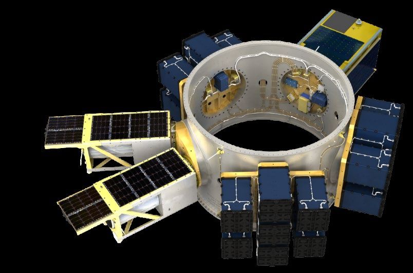
Document Overview
This Mission Planning Guide is published by Spaceflight, Inc. to provide general information regarding
Spaceflight’s mission management and integration services, as well as highlight best practices in
designing spacecraft for compatibility across launch opportunities. Additional information about
upcoming missions, launch pricing, and other offerings are available directly through
www.spaceflight.com.

This document is intended for planning purposes only and will be revised periodically; please check
the Spaceflight website for the latest revision. Actual compatibility requirements are defined on a
mission-specific basis. Questions or other requests may be directed to sales@spaceflight.com.

Revision History
  Rev       Approval Date                                     Changes
    A           2011-09-16       Initial Release

    B          2012-03-30        Updated electrical interfaces and launch environments

    C          2012-07-18        Official release

                                 Updated electrical interfaces and launch environments, reformatted,
    D          2013-03-05
                                 and added to sections

                                 Updated organization and formatting, added content on SHERPA,
    E          2014-04-15
                                 Mini-SHERPA and ISS launches, updated RPA CG

    F          2015-05-22        Overall update

    G          2019-02-12        Major revision

  © 2019 Spaceflight, Inc. All rights reserved.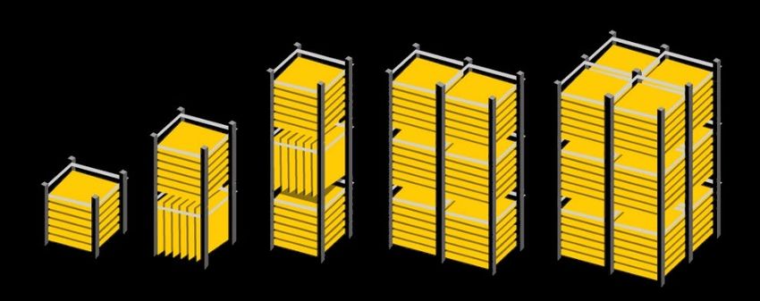
Table of Contents
1     Introduction                                             5

2     Finding Your Launch                                      7

    2.1   Getting Under Contract                               9

    2.2 Compliance Assessment                                  9

3     Managing Your Launch Service                             11

    3.1   Standard Services                                    11

    3.2 Optional Services                                      15

    3.3 Safety & Mission Assurance                             16

4     Designing for Compatibility                              19

    4.1   Rideshare Spacecraft Environments                    19

    4.2 Rideshare Spacecraft Design Compatibility Guidelines   26

5     Planning Your Launch Campaign                            36

    5.1   Logistics and Spacecraft Transportation              36

    5.2 Facilities and Ground Support Equipment                37

    5.3 Operations                                             43

6     Quick Reference                                          48

    6.1   List of Figures                                      48

    6.2 List of Tables                                         48

Appendix A: Acronyms and Abbreviations                         49

Appendix B: Technical References                               50

Appendix C: Spaceflight CubeSat Compatibility Guideline        51
1 Introduction
1 Introduction
Spaceflight is a premier launch services and mission management provider, offering flexible, frequent,
and cost-effective access to space for small spacecraft so you can innovate from a celestial perspective.
Founded in 2011, Spaceflight is a launch service provider offering end-to-end launch services across all
planning phases from mission design through deployment on orbit. As the pioneering company of
commerical rideshare in the US, Spaceflight is pleased to serve commercial companies, government
entities, and non-profit organizations in executing the most cost-effective launch campaigns on the
planet.

Spaceflight’s end-to-end launch services include:
    -   Capacity-booking sales team connected to almost every launch provider on the planet
    -   Provision of flight hardware and support equipment including structures, avionics, separation
        systems and signals
    -   Requirements, verification, and deliverables management to support integration & launch
        campaigns
    -   Payload integration facilities and experienced integration technicians to support physical
        integration of spacecraft to separation system and subsequently to launch vehicle
    -   Launch and deployment into desired orbit

What makes Spaceflight the best launch provider option for SmallSats? When choosing Spaceflight to
manage a launch contract, you are leveraging:
   1. Access to a broad range of launch vehicles, orbits, and launch timelines via a highly skilled single
      point of contact
   2. Lower launch costs achieved through preferred pricing and aggregated rideshare demand
   3. An engineering workforce that spans mechanical, electrical, systems, and program management
      disciplines who have successfully launched 200+ spacecraft
   4. Robust contracting with an organization capable of navigating schedule and programmatic
      changes over the life of the program with the ability to re-manifest onto other launch
      opportunities
   5. Flexibility to choose the level of service at the budget required by your program goals
   6. Compliance specialists in export and spacecraft licensing
   7. Logistics professionals experienced in global shipments of space hardware
   8. A dedicated mission management team using streamlined tools, processes, and communications
      resulting in significant time savings for your team

Spaceflight reserves both dedicated and excess launch capacity based on the demands of spacecraft
launch needs and manages each spacecraft mission from launch selection through deployment on orbit.
Spaceflight does this through established relationships with commercially competitive launch vehicles,
and proven mission design, management and integration processes. Spaceflight can accommodate any
set of constraints to help find you the right launch, at the right time, to the right orbit for the best price.
Get started today at Spaceflight.com.

Inside this Mission Planning Guide, you will learn why Spaceflight is the go-to rideshare source for Finding
Your Launch, Managing Your Launch Service, Designing for Compatibility, and Planning Your Launch
Campaign.

                                                       Rev G                                                 5
2             Finding your
                  Launch

                         Rev G   6

Photo credit: ISRO
2 Finding Your Launch
Whether it’s your first launch or your hundredth, finding and booking a launch with Spaceflight is simple.
The process begins by contacting Spaceflight’s business development team to provide some initial
information related to desired orbit, launch timing, expected spacecraft size (volume, mass, separation
system interface type), and unique spacecraft requirements. Spaceflight then creates a list of all available
launches compatible with your supplied criteria.

As one of the founding members of the commercial rideshare market for small satellites, Spaceflight has
long-standing relationships with established launch service providers, and actively fosters the growth of
emerging launch service providers around the world. With decades of experience working and launching
with such a wide variety of launch service providers, Spaceflight’s mission management and engineering
teams are well versed in the hardware, interfaces, and processes for spacecraft compliance and
integration and can help provide insight on the specifics of each when selecting a launch.

Increasingly, rideshare interfaces occur as a part of a host space vehicle rather than the launch vehicle
itself. In this case, Spaceflight’s experience with both the host space vehicle and launch vehicle benefit
rideshare spacecraft in the definition and execution of hardware, interfaces, and processes. Figure 2-1
illustrates the family of launch vehicles on which Spaceflight is actively manifesting missions; the number
of available vehicles is increasing as new launchers prove their capabilities.

                                                   LEO only                                                                             LEO and beyond
                                                                                                                 Soyuz CSG
                                                   Alpha

                                                                                                                                        GSLV MkIII
                         Launcher One

                                                                                                                                                                Falcon Heavy
                                                                                               Antares
                                                                               SSLV
                                                           Vega
   Electron
   Vector-R

                                                                  Minotaur-C
                                        Terran 1

                                                                                                                             Falcon 9
                                                                                                         PSLV
                                                                                      Vega-C
              Vector-H

                                                                                                                                                     Ariane 5

                                                                                Figure 2-1 Launch vehicle family

                                                                                                         Rev G                                                                 7
In order to maximize the number of rideshare interfaces (and thereby decrease the launch cost per
spacecraft), Spaceflight uses a variety of different structures and systems to interface with the launch
vehicle and other flight hardware. Typical rideshare interfaces can support CubeSats ranging from
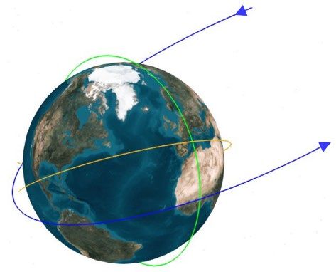
Low Earth Orbits:
                                                                Sun Synchronous (green)
                                                                Mid-inclination (orange)

                                                                     Transfer Orbits: GTO, cis-lunar (blue)

                                  Figure 2-3 Common Rideshare Insertions:

2.1 Getting Under Contract
Based on the identified launch opportunities, Spaceflight provides preliminary pricing and mission
information, iterating as needed, and culminating in a firm fixed price so there are no surprises later.
Once a spacecraft provider is ready to commit to a launch, the contracting process begins with a Letter of
Agreement (LOA), which is a binding reservation for launch capacity that captures the high-level terms
and conditions for the Launch Service Agreement
(LSA). Upon signing the LOA, Spaceflight assigns a                Identifies spacecraft, one or more launch
                                                                  opportunities which service the desired orbital
mission manager who becomes the single point of
contact for all spacecraft provider and launch        Quote       parameters and pricing

vehicle interactions including mission planning,
integration, and execution after the LSA is
                                                                  Letter of Agreement captures high-level terms
completed. The LSA follows soon after LOA                         and conditions of the binding contract
signing and commits the spacecraft to a specific        LOA
launch opportunity. It also includes the required
flow down clauses from the associated launch
                                                                  Launch Service Agreement expands upon LOA
vehicle provider and applicable governmental                      terms and incorporates exhibits unique to the
bodies followed by a detailed Statement of Work                   launch opportunity and Launch Service
(SOW) with clear deliverables and mission               LSA       Document Package including SOW
timelines for submission.
                                                              Figure 2-4 Spaceflight’s contract process flow
2.2 Compliance Assessment
A compliance assessment is conducted during the contracting process to determine what export licenses
are required, if there are any International Traffic in Arms Regulations (ITAR) or Export Administration
Regulations (EAR) restrictions or reporting requirements, and a compliance plan is outlined. Spaceflight
executes against this plan and provides guidance to spacecraft providers throughout the mission to ensure
compliant exchange of controlled technical data with spacecraft and launch providers as well as transport
hardware under the appropriate export licenses. While the compliance and export process can be lengthy
and complicated, Spaceflight’s compliance team has extensive experience successfully navigating the
applicable regulations to obtain the required export licenses and approvals necessary for launch. This
early assessment reduces program risk and gives the Spaceflight and spacecraft provider teams a roadmap
for compliant mission execution.

                                                      Rev G                                                    9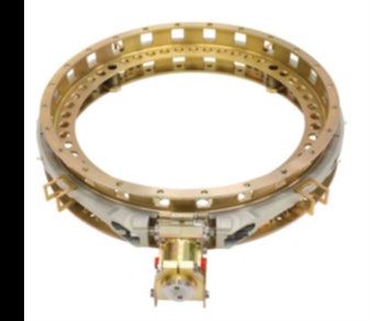
3    Managing
    your Mission

              Rev G   10
3 Managing Your Launch Service
Spaceflight’s core value to the rideshare community is exhibited through our team of talented mission
managers and integration engineers who ensure each aspect of the mission is prepared for a successful
launch campaign and deployment. This skill base is built upon an established track record of success over
more than 14 missions involving 200 satellites across seven different launch vehicles. Thanks to a uniquely
equipped team with insight into a wide variety of launch opportunities, Spaceflight is able to utilize late
manifest changes to benefit the SmallSat community in a way no other launch provider can offer.
3.1 Standard Services
The following services are included in every launch contract. Spaceflight is always willing to discuss unique
needs and services that might be above and beyond to scope the perfect mission.
3.1.1 Launch Management
Your Spaceflight mission manager serves as a single point-of-contact (POC), through whom all data and
communications are routed for the duration of the program. Through recurring meetings, Spaceflight
mission managers serve all aspects of project management from campaign kickoff through confirmation
of deployment on orbit. The tasks of a mission manager include:
• creation and management of schedule and Interface Control Documentation (ICD)
• provision of templates for deliverables
• completion and distribution of mission analyses
• detailed review and feedback on deliverables
• assessment of compliance to requirements
• action tracking
• guidance for range safety deliverables
• export license arrangement
• logistics coordination and support
• provisions of standard Ground Support Equipment (GSE)
• facilitation of spacecraft-specific engineering analyses (e.g. deployment, re-contact,
environments derivation, and waiver assessments).
Spaceflight’s mission management team is charged to advocate for the spacecraft provider internally and
externally, tirelessly seeking to meet the needs of the spacecraft provider with a focus on the specific
spacecraft needs. Spaceflight’s mission managers provide a satellite-focused and satellite-driven
experience, as compared to that of a contemporary launch vehicle provider.
3.1.2 Schedule and Deliverables
The mission management process occurs over a period of time averaging 12 or more months before the
scheduled launch date, with more complex missions requiring more time to execute. An example mission
management timeline is summarized in Table 3-1. The mission-specific schedules released over the
course of the mission include Overall Program Schedule, Integration Schedule, and Launch Campaign
Schedule. The purpose of these schedules is to drive spacecraft provider deliverables to completion in
support of the mission timeline, and to inform planning schedules for mission support.
During the launch planning process, Spaceflight serves to simplify the process of both understanding and
executing required documentation outputs from spacecraft provider to Spaceflight. The following
Rev G 11sections contain an overview of both what is expected from spacecraft teams and what you can expect to
receive from Spaceflight to get your spacecraft successfully on orbit.
Table 3-1 Sample mission management timeline and deliverables
Milestone Date Spaceflight Deliverables Spacecraft Provider Deliverables
- Procure deployment system
- Requirements for CAD & FEM,
Contract Signing thermal models
- Completed spacecraft questionnaire
Typically L-12+ months - ICD Template
- Apply for export licensing (as
required)
- Mission Schedule - Spacecraft CAD model
Kickoff
- Safety submission template - Spacecraft FEM
LSA signature+2 months
delivery - Spacecraft Test Plan
- Updated CAD model (if applicable)
- Updated FEM (if applicable
- Updated mission schedule - Thermal Model
- Current best estimate launch - Updated Spacecraft Mas
Mission CDR
campaign schedule - Completed Safety Submission
Launch-9 months
- Preliminary Integration Schedule - Spacecraft launch site operations
- Preliminary Launch Operations Plan plan
- Spacecraft licensing information sent
to appropriate agency
- Updated mission analyses results (if
- Verification compliance to ICD
applicable)
requirements (i.e. test reports)
System Readiness Review - Final integration schedule
- Updates to CAD, FEM, thermal
Launch-3 months - Final launch operations plan
model, and Safety Package (if
- A list of facilities and services
applicable)
available for spacecraft checkout
- Final as-measured spacecraft mass
and best estimated wet-mass
- Delivery of Spacecraft and associated
- Identify last access to the
electrical and mechanical GSE to
Integration Process Start spacecraft
integration facility for system level
Launch-60 days - Spaceflight provides the integration
integration
facility
- Delivery of spacecraft mass simulator
to integration facility for system level
integration
Launch Readiness Review
- Approximate separation time - Launch Readiness Review (LRR)
Launch-1 day
Launch
- -
Launch+0 hours
Spacecraft Separation - Separation confirmation and state
-
Launch+4 hours vector
Acquisition Notification - Indication of spacecraft acquisition,
Spacecraft Acquisition+12 - state-of-health assessment
hours
Rev G 12A description of the typical mission deliverables both provided to and expected from spacecraft providers
is included in Table 3-2. These documents represent the general types of necessary content required to
be communicated between the rideshare spacecraft, the launch vehicle provider, and various support
agencies associated with the launch. Specific documentation needs are provided once a spacecraft is
manifested on particular mission.
Table 3-2 Description of Deliverables
Item Deliverables from Spacecraft Provider to Spaceflight
Spacecraft Questionnaire – The spacecraft questionnaire includes the orbit requirements, interface
1
details, mass properties, preliminary drawings, and unique spacecraft requirements, etc.
Verification Artifacts – Provide documentation to serve as verification artifacts of all ICD requirements
2
(includes spacecraft system design information, test plans and results, Certificates of Compliance, etc.)
Spacecraft CAD Model – CAD model showing the outer mold line configuration, shape, and dimensions of
3
the satellite.
Mass Properties Report – Current best estimate mass properties are tracked from spacecraft
4 questionnaire through Mission Readiness Review. The values should include the nominal values and 3σ
uncertainties.
Safety Package – The Safety Package is a data package that provides detailed technical data on all
5 hazardous items including drawings, schematics, RF Radiation, and assembly and handling procedures
(format is dependent upon Launch Range).
Spacecraft Launch Operations Plan – Each spacecraft must specify any handling constraints,
6 environmental constraints, personnel requirements, equipment requirements, launch site checkout
procedures, integration procedures, and the duration of these tasks for their satellite.
Spacecraft Finite Element Model (microsats only) – A spacecraft FEM is required for inclusion in Coupled
7
Loads Analysis.
Spacecraft Thermal Model (microsats only) – A spacecraft thermal model is required for inclusion in an
8
integrated thermal analysis
Spacecraft licensing - Copies of all licenses, permits, clearances, authorizations, and approvals necessary
for the transportation of, communication with, operation, launch and orbital deployment of the spacecraft
9 including, but is not limited to all licenses from: the Federal Communications Commission (“FCC”) or
spacecraft provider’s applicable national administration/agency; and if applicable, the National Oceanic
and Atmospheric Administration (“NOAA”).
Item Deliverables from Spaceflight to Spacecraft Provider
ICD – Interface Control Document defining mission, interface, and operational spacecraft requirements
1 necessary to successfully execute the launch service, including acceptable verification methods and
verification artifacts for each of the requirements.
2 Deliverable input guidance – Provide deliverable templates and feedback on draft submissions.
Schedule – Description of the mission planning timeline and status of readiness activities to ensure the
3
team is on-track to meet mission milestones.
Mission Unique Design Analyses – Provide current best estimates through coordination with launch
4
vehicle team for launch environments, targeted orbital parameters, and deployment timing.
Spacecraft and Mission Readiness Review – Provide readiness status for spacecraft, Spaceflight hardware
5 and facilities to execute launch campaign.
State vector and deployment confirmation – Actual insertion parameters and separation confirmation on
6
orbit.
Rev G 133.1.3 Mission Feasibility Analysis
As a part of the launch contract preparation process, Spaceflight’s mission management and engineering
teams evaluate compatibility of spacecraft design with a given launch opportunity based on the
information provided in the spacecraft questionnaire. These assessments typically include
packaging/volumetric configurations, mass properties analysis in relation to rideshare adapter and
deployment system capabilities, as well as alignment with standard integration flow and timelines.
3.1.4 Coupled Loads Analysis
Spaceflight combines spacecraft finite element models along with Spaceflight-provided hardware models
to provide input to the launch vehicle combined Coupled Loads Analysis (CLA). The CLA is used to
determine maximum predicted dynamic environments for spacecraft interfaces when excited by the
launch vehicle for that specific mission; as such, CLA outputs include maximum accelerations and interface
loads at selected nodes of the spacecraft. To facilitate these analyses, each spacecraft provider (with the
exception of CubeSats) is expected to provide a simplified NASTRAN finite element model representative
of the flight configuration. The mission schedule includes sufficient time to update models and update
the coupled loads analysis if there are significant changes in the models or environments from the initial
iteration.
3.1.5 Thermal Analysis
Spaceflight performs thermal analyses to provide minimum and maximum predicted spacecraft
temperatures from the time of fairing encapsulation until the rideshare spacecraft is deployed from the
launch vehicle. Accordingly, each spacecraft provider (with the exception of CubeSats) is expected to
provide a thermal model, where nodes of particular interest can be called out for time-history profiles.
Complexity of the thermal model required may vary, depending on the size of the spacecraft and the
fidelity of the thermal interfaces required.
3.1.6 Separation Timing and Re-Contact Analysis
Spaceflight uses a combination of mission requirements, separation system specifications, spacecraft
mass, spacecraft orientation, and other variables that contribute to the re-contact possibility to develop
a deployment timeline. The separation timing and re-contact analysis informs deployment timelines to
ensure that minimum separation thresholds are maintained between the launch vehicle upper stage and
deployed spacecraft.
3.1.7 Range Safety Review
Each spacecraft provider is responsible for ensuring that they are in compliance with the applicable Range
Safety requirements included in the ICD. This is primarily accomplished through each spacecraft
provider’s safety package submissions in addition to requirement tailoring inputs (as applicable).
Spaceflight provides safety package templates and support throughout the range safety review process.
All spacecraft, GSE, and hazardous procedures must meet the safety requirements of the Launch Provider
and the Range Safety. Safety submissions generally include a clear description of your spacecraft including
potential hazards of your spacecraft. A description of structural design and environmental testing are
helpful to demonstrate that safety requirements have been met.
Components of particular interest in safety documents include fueling, ordnance systems, pressurized
systems, propulsion systems, radio frequency (RF) systems, laser systems, and electrical systems including
Rev G 14the battery type and associated testing. All hazardous procedures must be clearly described including
handling of hazardous materials. It is very important that spacecraft designers address Range Safety
concerns early in the spacecraft design process to ensure compatibility with requirements.
3.1.8 Spacecraft to Separation System Fit Check
Spaceflight arranges pre-integration fit checks to ensure proper fit with separation system and finalization
of integration procedures well before spacecraft arrival to integration facility. Access to the spacecraft is
limited following integration onto the launch vehicle so the fit check dry run allows for any telemetry
connections and/or green tag and Remove Before Flight (RBF) items to be rehearsed before flight
integration occurs. Fit check also includes Spaceflight-provided electrical harnesses that connects the
separation system to the spacecraft and launch vehicle, as well as standard GSE to support the separation
system during integration of spacecraft to the launch vehicle. For the purposes of this document, GSE
includes Mechanical and Electrical Ground Support Equipment (MGSE and EGSE).
3.1.9 Licensing Compliance Review
Following the submission of the required licensing to Spaceflight, a review of licenses is completed to
ensure licensing is compliant with mission requirements. All spacecraft providers are required to
independently determine and obtain the licenses necessary for the spacecraft. Spaceflight does not
integrate or launch spacecraft unless copies of regulatory licenses allowing the spacecraft owner to
launch, deploy, and operate the spacecraft are provided and certified as true and correct. These
requirements vary for each country. Spaceflight can provide resources early in the mission planning to
help navigate required licensing for the spacecraft provider national agency or administration.
Spaceflight helps spacecraft providers avoid licensing pitfalls and risks to integration readiness by
providing thorough review of a spacecraft provider’s licensing scheme and issued licenses to ensure
compliance.
3.2 Optional Services
As every mission requires some unique accommodations for spacecraft, Spaceflight provides a myriad of
optional services in addition to the standard services as listed in Table 3-3.
Table 3-3 Optional services available
access to spacecraft for late charging
accommodations for spacecraft fueling
custom GSE
flexible launch re-manifest launch contracting
launch insurance
loan of test fixture
mission feasibility analyses (in advance of launch contract signing)
nitrogen purge
non-standard (especially early or late) spacecraft delivery timeline
pre-planned extended duration processing time during an integration campaign
provision of propellants
separation system rental for testing
separation system tuning for customized tipoff rates
Spaceflight-procurement of customer mass simulator
Rev G 153.3 Safety and Mission Assurance
Said simply, a launch service lacking in quality assurance does not survive. Spaceflight’s livelihood
depends on flawless deployment of spacecraft on orbit where all personnel and property survive safely
along the way. To achieve this end, Spaceflight’s team relies on proven mission assurance practices,
effective demonstration of compliance to safety requirements, and quality management systems to
provide a cost-effective, high-quality launch service.
3.3.1 Mission Assurance
At Spaceflight, mission assurance encompasses an overall “Do No Harm” methodology. In principle,
Mission Assurance is the disciplined application of proven scientific, engineering, quality, and program
management principles toward the goal of achieving mission success. It follows a general systems
engineering framework and uses risk management and independent assessment as cornerstones
throughout the mission life cycle. Spaceflight’s two major objectives of mission assurance are:
1. Successful separation of rideshare spacecraft in orbit
2. Rideshare spacecraft “Do No Harm” to each other or the mission
Overall mission assurance is achieved through disciplined systems engineering practices, risk
management, quality assurance processes, independent assessment throughout the mission lifecycle, and
a “Test like you fly” philosophy. The internal assessments performed by Spaceflight throughout the
lifecycle vary depending on the mission type and complexity including reviews by the Engineering and
Program Management leadership to ensure requirements verification, mission and integration readiness,
and launch readiness. Each internal assessment has a clear set of entrance and exit criteria that must be
met to gain approval. The reviews focus on the state, status, and performance of units, subsystems,
systems, development, production, testing, and risk. The reviews may also cover program management
processes, engineering processes, hardware acceptance, materials control, system safety, quality
assurance, discrepancy reporting, contamination control, and configuration management. Mission
assurance is tailored to meet the needs of each mission and launch, as well as each spacecraft provider.
The “Do No Harm” methodology ensures that the multiple co-passengers on a launch do not cause
adverse effects on each other, the launch vehicle, or otherwise negatively impact the mission. Structural
integrity is assured by defining and testing to enveloping dynamic environments for each launch vehicle,
while also considering unique sub-systems and RF compatibility and application of mission constraints and
requirements. Spaceflight relies on a clear set of repeatable processes to ensure that mission
requirements are met based on industry-proven standard practices levied through the ICD. It is through
the verification of these mission requirements that the highest probability of mission success exists.
Spaceflight’s mission managers play the key role in the overall mission assurance process, where explicit
compliance is verified by the Quality and Mission Assurance Manager. Through clear communication,
realistic scheduling, and targeted engineering focus, Spaceflight actively addresses technical risks until
closure through regular review of progress and action item status for all parties. The mission manager
owns the requirements, as well as the relationship to vendors, suppliers, and other spacecraft providers
including visibility to which approvals must be in place prior to launch.
3.3.2 Safety Submissions
Spaceflight’s heritage across many launch vehicles provides unique insight into the intricacies of the
distinct requirements and deliverables associated with each launch vehicle and launch range. Approval
Rev G 16of safety submissions including details of the hazards present in a spacecraft’s system and processes is a
necessary part of ensuring mission success during integration and while at the launch range. Accurate
and thorough safety submission documents are important because in the event of an anomaly during
ground processing or launch, Range Safety may use all available documentation to complete an audit and
investigation.
3.3.3 Waivers
As spacecraft providers evaluate compliance to the applicable mission requirements, in extenuating
situations, a waiver may be requested to either tailor the language or level of the requirement, allow for
alternate means of verification or waive the requirement entirely. The best practice is to meet all of the
requirements of the ICD, as waiver requests are subject to approval by Spaceflight, launch vehicle provider
and range safety as required to ensure an equivalent levels of safety results and the ‘Do No Harm’ criteria
is met.
3.3.4 Quality Assurance
Spaceflight maintains a process-based Quality Management System (QMS) and is committed to ensuring
our products and services meet or exceed customer expectations. As part of the company’s management
reviews, internal audits, corrective actions, preventive actions, risk management, continual improvement
activities and review of customer feedback / satisfaction measures, all QMS processes are analyzed to
determine process effectiveness, product conformance, and customer satisfaction.
Spaceflight flight hardware is under configuration control, with all design, integration, and test activities
executed to released, revision-controlled documentation. Tooling and test equipment used in the
acceptance loop for flight hardware is regularly calibrated and maintained. Work documentation records
are captured and maintained in accordance with our QMS documented processes. Supplier-provided
hardware is inspected to ensure product quality prior to use with flight systems.
Rev G 174 Designing for
Compatibility
Rev G 184 Designing for Compatibility
Outside of spacecraft functionality on orbit, it is the launch configuration and environment that most
dramatically shapes spacecraft design. When it comes to understanding what constraints exist across
launch opportunities, Spaceflight offers significant value to spacecraft providers on how to navigate this
challenging topic based upon the success of prior missions. The sections that follow contain high level
insight on rideshare spacecraft environments and rideshare spacecraft design compatibility guidelines to
support the rideshare community in preparing for a wide variety of launch opportunities. The most
effective things a spacecraft developer can do to optimize their compatibility across launch
opportunities are to comply with the industry standards and develop a simple system both in operation
and ground handling.
4.1 Rideshare Spacecraft Environments
Whether launching for the first time, considering new launch vehicles, or investigating rideshare,
identifying the bounding spacecraft environments for your design is a challenging but important step in
preparing well for your mission. It is ultimately the spacecraft provider’s responsibility to ensure the
spacecraft survives all environments encountered during the course of the mission; Spaceflight makes it
easy to access the environments, to understand how those environments are revised over time (including
waiver requests), and to know what verifications are expected to demonstrate that a spacecraft is fit for
flight.
The following sections summarize the baseline mission environments for rideshare spacecraft by
presenting an envelope of the most common rideshare mission environments. These environments
represent a conservative approach to the satellite design and should not be used to determine the
absolute compatibility with launch opportunities that Spaceflight has available. Spaceflight understands
that designing to overly conservative environments can impose the possibility of greater system mass and
overall cost to the spacecraft provider. We encourage early engagement with our team during your
spacecraft design process to best understand what conservatisms apply for the mission of interest. By
working closely with Spaceflight, spacecraft providers gain insights that allow them to perform trade
studies to weigh the costs of cross-mission compatibility versus single launcher compatibility. Note that
the values included herein represent maximum predicted environments, whereas actual test values would
require application of appropriate factors of safety applied to the environments as stated (or more
appropriately, environments as stated in the mission-specific ICD).
During early mission scoping, Spaceflight initially specifies mission environments based on best estimates
using payload user’s guides, past experience, and internal analyses. The mission environments are
iteratively refined through coordination with the launch vehicle provider until final maximum predicted
environments are provided as a part of the mission-specific launch vehicle critical design review.
Rev G 194.1.1 Quasi-Static Loading Environment
Table 4-1 Enveloping quasi-static loading guidelines
Larger Microsats Smaller Microsats
CubeSats
(typically >60 kg) (typically ≤60 kg)
≤10 g in flight. Axis of highest ≤15 g in flight. Axis of highest 15 g non-simultaneously in each
load and simultaneity is often load and simultaneity is often orthogonal axis when
mission dependent, where mission dependent, where constrained in a flight-like
typical max loading occurs in typical max loading occurs in manner (either tabs or rails
launch vehicle thrust axis. launch vehicle thrust axis. depending on the specific
deployment system).
For microsats, a useful method for determining bounding accelerations for spacecraft in advance of
mission-specific loads availability can be derived from JPL D-5882 “Mass Acceleration Curve for Spacecraft
Structural Design.”
Actual loads, accelerations, and deflections are a function of the launch vehicle, primary spacecraft, and
other rideshare spacecraft dynamic structural properties. These are accurately determined via mission-
specific analyses, typically through CLA. Spacecraft providers are highly encouraged to communicate any
existing quasi-static qualification history to Spaceflight upon initial discussion of launch opportunities to
incorporate into the mission feasibility analysis. However, Spaceflight recommends spacecraft providers
also reserve the ability to perform quasi-static qualification after mission-specific environments are
determined to ensure tests are performed to the appropriate levels. Testing to conservative quasi-static
acceleration levels affords the spacecraft providers with the widest range of possible launch
opportunities.
4.1.2 Sinusoidal Vibration Environment
Some launch vehicle providers expect spacecraft to undergo sinusoidal (sine) vibration testing to
demonstrate acceptability for flight. The sine vibration environment is defined as an input at the
spacecraft interface and may be requested to be notched to avoid overtest at certain frequencies.
Table 4-2 Sine vibration environment guidelines
Microsatellites CubeSats
The sine vibration environment is based on CLA performed by the In instances where spacecraft
launch vehicle provider. The results from CLA are used to derive fundamental frequencies do not
a response spectrum of the vibration levels at the spacecraft exceed the baseline requirement
interface. For a given modal damping value, a smoothed envelope (Section 4.2.1.1.14), CubeSats may
of peak responses is created, which is then used to produce a sine be required to demonstrate
vibration input curve. compliance to sinusoidal vibration
environments.
4.1.3 Random Vibration Environment
The random vibration environment is highly unique to each mission. Spaceflight provides generic mission
acceptance-level enveloping environments to assist spacecraft developers with maximizing their flight
opportunities. Spacecraft providers who design for the random vibration environments in Table 4-3 below
can take advantage of the greatest flexibility across Spaceflight’s launch offerings. Mission-unique flight
environments are communicated to the spacecraft provider via the ICD.
Rev G 20Figure 4-1 Enveloping random vibration environment profiles
Table 4-3 Enveloping random vibration environment profiles
Microsatellites CubeSats
Frequency (Hz) Acceptance PSD (g²/Hz) Frequency (Hz) Acceptance PSD (g²/Hz)
20 0.057 20 0.057
40 0.057 35 0.057
50 0.060 50 0.080
800 0.060 800 0.080
1300 0.050 1300 0.050
2000 0.050 2000 0.050
gRMS 10.5 gRMS 11.3
Each spacecraft is expected to survive a 2-minute random vibration test in all three axes to ensure that it
will both survive to accomplish its mission and not pose harm to other spacecraft during launch.
Should a spacecraft design not be compatible with high frequency mission environments as stated in a
mission-specific ICD, spacecraft designers may consider isolation systems that can effectively move more
energy into lower frequency regimes experienced by the spacecraft. Given the need to address specific
aspects of incompatibility, isolation systems are inherently associated with a specific mission and thereby
reduce compatibility across launch opportunities.
4.1.4 Acoustic Environment
Two acoustic environments are shown in Figure 4-2. Env 1 envelops the qualification acoustic
environment expected for all missions to Low Earth Orbit. Env 2 envelops the qualification acoustic
environment for GTO missions. Acoustic qualification tests are expected to be 2 minutes in duration.
Acoustic acceptance tests are typically 3 dB lower at all frequencies and the test duration is 1 minute.
Spacecraft with large flat surfaces are typically susceptible to acoustic environments. Acoustic testing is
recommended for any spacecraft with structural components susceptible to excitation by acoustic
Rev G 21environments, though many microsats of smaller form factor may find that random vibration
environments envelop acoustic environments for a particular mission. CubeSats do not typically undergo
acoustic testing due to their small size, protection from direct acoustic excitement inside a dispenser, and
the random vibration environment enveloping acoustic environment.
150
Env 1 (147.1 dB OASPL)
Sound Pressure Level (dB) (ref: 0 dB = 2e-5 Pa)
140 Env 2 (141.8 dB OASPL)
130
120
110
100
90
80
10 100 1,000 10,000
Frequency (Hz)
Figure 4-2 Enveloping acoustic environment profiles
4.1.5 Shock Environment
In many rideshare situations, the shock environment induced by
Table 4-4 Shock environment
a spacecraft separation system envelops the shock environment
Frequency (Hz) Amplitude (g)
induced by launch vehicle events (e.g. fairing separation, stage
100 40
separation, etc.). The launch vehicle-induced shock environment
1,000 1,000
is highly mission-specific so Spaceflight recommends all
10,000 1,000
spacecraft (including CubeSats) be tested to either the following
environment (see Table 4-4) or the shock environment supplied by the separation system vendor
(whichever is higher). Spaceflight may need to levy a higher shock environment on a mission-specific
basis. Spaceflight recognizes that shock testing is something of an art and that it can be easy to
unintentionally overtest; through clear definition of test levels based on mission specific requirements,
Spaceflight regularly assists rideshare spacecraft in completing shock tests successfully.
4.1.6 Depressurization Environment
Spaceflight recommends all spacecraft providers design their spacecraft to the following depressurization
environment, which envelops all potential launch opportunities:
• Sustained depressurization: 2.8 kPa/sec (28 mBar/sec or 0.40 psi/sec)
• Transient: 4.8 kPa/sec (48 mBar/sec or 0.70 psi/sec) for as much as 5 seconds
Rev G 22Due to the specialized test facilities that are required to perform depressurization testing, Spaceflight
accepts verification by both analysis and/or test.
• For CubeSats, this is often as simple as looking at the ratio of volume to be vented to vent area.
A minimum ratio is 2000 inch³/inch², referenced in the CubeSat Design Specification, is often used.
• For microsats, Spaceflight prefers to see additional work to show that the pressure differential
induced by depressurization will not cause structural failure. Under certain circumstances,
Spaceflight may ask for specific vent directions to be blocked in order to prevent one spacecraft
from venting directly onto (and therefore possibly contaminating) another.
4.1.7 Electromagnetic Environment
The following figure shows the enveloping electromagnetic interference (EMI) environment across all
launch opportunities for both LEO and GTO missions. Spaceflight recommends all spacecraft be tested to
either the LEO or GTO environment, as appropriate, to ensure the spacecraft will survive (and not change
power state during exposure to) EMI caused by the range, the launch vehicle, and other sources.
180 LEO
Radiated Emissions Environment (dBµV/m)
160 GTO
140
120
100
80
60
40
20
0
0.1 1 10
Frequency (GHz)
Figure 4-3 Enveloping electromagnetic environment
4.1.8 Limits to Spacecraft Radiated Emissions
Spaceflight requires all rideshare spacecraft to meet launch range and launch vehicle EMI susceptibility
criteria, which have been summarized in this section. Spacecraft are expected to be tested in an anechoic
chamber in the launch configuration (including power state). Rideshare spacecraft are also expected to
inhibit intended RF emissions until after deployment in orbit. Spaceflight can make arrangements for
spacecraft RF testing at specific times during the integration process with appropriate prior planning. The
limits posted here envelop all missions and launch opportunities. Spacecraft providers can expect less
restrictive limits to be defined in the mission-specific ICD.
Rev G 23Figure 4-4 Radiated emissions limits for rideshare spacecraft (LEO missions)
Table 4-5 Radiated emissions limits for rideshare spacecraft (LEO missions)
RF emissions limit (dBµV/m)
Frequency Range imposed on spacecraft
All frequencies 70 unless noted below
105 MHz to 155 MHz 20
315 MHz to 345 MHz 35
395 MHz to 485 MHz 20
950 MHz to 1210 MHz 30
1500 MHz to 1700 MHz 20
2000 MHz to 2200 MHz 20
2200 MHz to 10 GHz 20 to 70
Table 4-6 Radiated emissions limits for rideshare spacecraft (GTO missions)
RF emissions limit (dBµV/m)
Frequency Range imposed on spacecraft
All frequencies 30
4.1.9 Thermal Environments
4.1.9.1 Pre-flight Thermal Environment
The pre-flight thermal environment encompasses the phases from unpacking and integration within the
integration processing facility, transportation to the launch site, and mission- and launch vehicle-specific
encapsulated pre-flight phases. Based on Spaceflight’s experience across multiple missions, we
recommend all spacecraft providers design their spacecraft to survive the pre-flight environmental
conditions stated in Table 4-7.
Rev G 24Table 4-7 Enveloping thermal environments
Integration & Launch Site Ground Transportation Encapsulated prior to Launch1
• Temperature: 13˚C to 30˚C • Temperature: 13˚C to 30˚C
• Relative Humidity: 30% to 65% • Relative Humidity2: 0% to 65%
• Cleanliness Class 8 (ISO 8 or 100k) • Cleanliness Class 8 (ISO 8 or 100k)3
Note 1: This table is an example. Certain missions may deviate from these values.
Note 2: Many launch vehicle providers have facilities and equipment to allow the prime spacecraft to specify the
desired humidity limits
Note 3: Some integration facilities offer filtered air that is cleaner than Class 8.
Pre-flight environmental conditions are further refined throughout the mission planning process and are
officially communicated via the ICD. Spacecraft providers can expect much tighter tolerances on these
conditions, especially during integration and post-integration testing (microsats only) phases.
4.1.9.2 Ascent Radiated Thermal Environment
During ascent, spacecraft (particularly microsats) are exposed to thermal radiation from the interior walls
of the launch vehicle fairing. The extent to which this affects each spacecraft is a function of several
factors:
• Specific launch vehicle (fairing design, trajectory, etc.)
• Location of the spacecraft within the fairing
• Blockages/shadowing caused by adjacent structures
In most cases, the ascent thermal environment for any given spacecraft is enveloped by the spacecraft’s
own on-orbit thermal environment. Unique thermal sensitivities should be provided in the spacecraft
questionnaire. For some missions, Spaceflight aggregates the thermal models of all rideshare spacecraft
and flight support equipment into a single thermal model with which the launch vehicle provider is
responsible for performing thermal analysis during the ascent phase.
CubeSats are typically shielded by their dispenser from the ascent thermal environment and are therefore
not significantly affected by the ascent radiated thermal environment.
4.1.9.3 Ascent Aerothermal Environment
Almost universally, launch vehicle fairings are jettisoned when the instantaneous aerothermal heat flux is
1135 W/m² or less (this value corresponds to the total energy flux from the Sun). Aerothermal heat flux
typically drops quickly from this value while the solar flux remains constant. Similar to the ascent radiated
thermal environment, microsats are more exposed to this environment than are CubeSats. Unique
thermal sensitivities should be provided in the spacecraft questionnaire.
4.1.9.4 On-orbit Aerothermal Environment
For rideshare spacecraft, the on-orbit thermal environment is dominated by solar flux as well as Earth
albedo but is also influenced by nearby rideshare spacecraft (via radiation) and flight support equipment
(via radiation as well as via conduction through the separation system). The duration of exposure and the
relative sun position(s) to any one spacecraft are highly mission specific. Spaceflight recommends that all
rideshare spacecraft be able to survive direct solar exposure on any spacecraft face for 65 minutes
continuously in the launch configuration. This value covers all but continuous-sun 6am/6pm LTDN sun-
synchronous orbits; spacecraft in continuous-sun 6am/6pm LTDN sun-synchronous orbits should be able
Rev G 25to survive direct solar exposure to any spacecraft face continuously for 6 hours. Conversely, Spaceflight
recommends that all rideshare spacecraft be able to survive no solar exposure for several orbits in the
event a spacecraft is shadowed until it separates. In many cases, Spaceflight can accommodate spacecraft
with unique thermal needs, but priority is given to primary spacecraft. For reference, thermal analysis
performed for previous rideshare missions has shown rideshare spacecraft temperatures often range
from -15°C to +40°C prior to deployment, where some missions experience more extreme temperatures
depending on the type and timing of orbital maneuvers involved.
4.2 Rideshare Spacecraft Design Compatibility Guidelines
The following sections describe general spacecraft guidelines for spacecraft providers to take into
consideration when evaluating compatibility with Spaceflight’s rideshare missions. The nature of these
guidelines fall into three general categories: “Do No Harm” requirements, design-for-launch
requirements, and others for safe operation at the launch site and on-orbit. The driving philosophy for
many of the guidelines presented in this section is “Do No Harm,” as all rideshare spacecraft are
manifested on a ‘non-interference basis’ avoiding conflict with other rideshare and primary spacecraft
and launch vehicle.
4.2.1 Design Guidelines
4.2.1.1 Spacecraft Design and Construction Constraints
4.2.1.1.1 Separation System Interfaces
There are many considerations that go into selection of a separation system; for example, mechanical and
electrical interfaces, shock, keep out zones, flyaway mass, thermal emissivity, reset and reliability
features. Having manifested spacecraft of all shapes and sizes, Spaceflight has experience procuring,
integrating, and deploying a wide variety of separation systems. While capable of accommodating nearly
any separation system, non-pyro systems that are easily resettable and do not create debris are preferred
and permit repeatable operations during fit checks, mission systems testing, and integration operations.
Spaceflight typically provides the separation system, separation signals, and the means to physically and
electrically attach the separation system to the launch vehicle (bolts, fasteners, etc.). The following
sections provide reference to common separation system types that have flight heritage on Spaceflight
missions.
4.2.1.1.1.1 Microsat separation systems
To maximize compatibility with existing missions, Spaceflight encourages spacecraft providers design to
interface with a proven clampband type separation system like those shown in Figure 4-5. These
clampband separation systems are lightweight, low shock, and interface easily with existing rideshare
adapter structures. Separation system designs with no flight or qualification by similarity heritage pose
significant challenges in qualification, integration, and reliability verifications and should be avoided. Keep
out zones, electrical interfaces, and other system specific details are provided in the mission-specific ICD.
Rev G 26Mk II Motorized Lightband PAS 381S Separation System
Photo credit: Planetary Systems Corporation Photo credit: RUAG
Figure 4-5 Example separation systems for microsats
Spacecraft providers are expected to own the interface on the spacecraft-side of the separation system
including the interfacing threads, specification of torque values, and provision of fasteners. Spaceflight is
well acquainted with the six+ month lead time associated with procurement of flight separation systems;
as such, determination of separation system is an important part of the launch contracting discussion.
4.2.1.1.1.2 CubeSat Separation Systems and Constraints
4.2.1.1.1.2.1 Rail-type Dispensers
Spaceflight has a great deal of heritage in providing launch opportunities for CubeSats on a variety of
launch vehicles and deployment systems, including spacecraft from ¼U to 12U sizes as shown in Figure
4-6. Rail-type spacecraft are expected to be compatible with the volume envelope described in Appendix
C: Spaceflight CubeSat Compatibility Guideline and the specifications outlined in the CubeSat Design
Specification (CDS) from California Polytechnic State University (Cal Poly San Luis Obispo). While CDS
defines permissible excursions in volume between the rails, the dispensers utilized by Spaceflight often
permit larger excursions than CDS describes, hence the difference in volume permitted according to
Appendix C: Spaceflight CubeSat Compatibility Guideline.
Spaceflight requires a fit check prior to integration of flight spacecraft to ensure spacecraft design is
compatible with dispenser interfaces and volume envelope. Spaceflight’s integration team facilitates joint
operation with spacecraft providers to install CubeSats into the dispenser, along the dispenser’s
longitudinal axis while in horizontal position. The spacecraft is then constrained by four hardened
anodized aluminum guide rails, the spring-loaded pusher plate, and the dispenser door. With the door
closed, the dispenser interface pressure suppresses chattering or rattling of the CubeSat during
transportation and launch.
Rev G 271U 2U 3U 6U 12U
Figure 4-6 Typical CubeSat sizes
Note that the release of CDS for 6U spacecraft defines a length longer for 6U satellites (366 mm) than the
3U-class satellites (340.5 mm). While standard dispenser sizes offered by Spaceflight include
accommodation of 340.5 mm length CubeSats, the longer 366 mm variant (commonly referred to as “XL”)
can also be accommodated upon request.
4.2.1.1.1.2.2 Tab-type Canisterized Satellite Dispenser
Spaceflight has significant experience utilizing an alternate CubeSat dispenser configuration which has a
different ‘tab-type’ spacecraft interface not compatible with ‘rail-type’ CubeSats. While tab-type
spacecraft are not expected to follow the structural interface guidelines in the CDS, they are expected to
follow all other CubeSat design guidelines and requirements as stated in CDS. Tab-type spacecraft are
expected to be compliant to Planetary Systems Corporation’s Payload Specification document (PSC
Document #2002367).
4.2.1.1.1.2.3 Considerations for Sub-3U spacecraft
For spacecraft smaller than 3U, there are unique requirements that drive spacecraft-to-spacecraft contact
and integration operations that are not covered explicitly in existing industry standards. Separation
switches are best positioned at the rail ‘feet’ ends such that switches will depress the same whether they
abut a spacecraft or dispenser structural feature. RBF and/or red tag/green tag items should be able to
be removed before insertion into the dispenser. Because sub-3U spacecraft need to be prepared for
integration with their neighboring spacecraft, spacecraft developers should plan to be able to utilize
resettable inhibit timers to prevent spacecraft operation should a particular integration operation not be
completed in the time allotted.
4.2.1.1.2 Material Selection and Outgassing Considerations
Spaceflight recommends utilizing materials that comply with NASA-STD-6016, Standard Materials and
Processes Requirements for Spacecraft. Non-alloyed tin, mercury, zinc, cadmium, and beryllium are
prohibited and are not to be used in the spacecraft design.
In order to prevent outgassing and reduce contamination of flight hardware, spacecraft designers are
expected to use materials that, when exposed to a vacuum environment, will not exceed a Total Mass
Loss (TML) of 1.0% and Collected Volatile Condensable Materials (CVCM) of 0.1% when tested on a
component basis per ASTM E595 or an equivalent method.
4.2.1.1.3 Coordinate System Definitions
In order to ensure clear transmission of mechanical properties from spacecraft provider to Spaceflight’s
engineering team, spacecraft designers are encouraged to orient spacecraft coordinate systems in
Rev G 28deliverables to Spaceflight with those of the deployment system being used. This helps provide data in
the same reference frame as Spaceflight uses, reducing possibilities for error by removing the need to
translate between coordinate systems.
4.2.1.1.4 Volumetric and Mass Envelopes
A spacecraft’s form factor (in its launch configuration) and mass are two important characteristics
necessary to determine a spacecraft’s compatibility with a given launch opportunity. Spaceflight
encourages spacecraft designers to very carefully consider form factors early on, as design decisions at in
early phases can significantly impact the number of compatible launch opportunities. Spaceflight helps
spacecraft providers understand the implications of spacecraft shape and mass characteristics early on in
the launch selection process. Utilizing existing standard interface sizes is encouraged: some examples are
the CubeSat Design Specification from Cal Poly, the ESPA User’s Guide from Moog, and the Launch Unit
from Aerospace Corporation.
Typical volumes and masses for rideshare class spacecraft are summarized in Table 4-8 below, though
other accommodations may be available. Volume limitations are dependent upon the size of the
neighboring structures, spacecraft, and fairing size. Contact Spaceflight with any inquiries regarding
spacecraft accommodations on rideshare missions.
Table 4-8 Spaceflight rideshare satellite class categories
CubeSats Microsats
3U 6U 12U
Mass (kg) 5 10 20 50 100 150 200 300
Length (cm) 34.05 34.05 34.05 80 100 100 100 125
Height/Dia (cm) 10 10 22.63 40 50 60 80 100
Width (cm) 10 22.63 22.63 40 50 60 80 100
The spacecraft provider is expected to conform to the mass-carrying constraints of the separation system
and rideshare structure(s) once selected. Spaceflight can help identify the center of mass constraints for
separation systems not readily available on the public domain; rail-based CubeSats should adhere to CDS’s
center of gravity guidelines, and tab-based spacecraft should adhere to Planetary Systems Corporation’s
Payload Specification document #2002367. Microsats with center of mass both aligned with the axis of
symmetry of the separation system and located as close to the separation system interface as reasonably
possible will have the widest selection of separation system options. Spacecraft providers are expected
to define uncertainties associated with any mass properties provided.
4.2.1.1.5 Orbit Disposal Guideline
All Spacecraft are expected to comply with the Inter-Agency Space Debris Coordination Committee (IADC)
Space Debris Mitigation Guidelines for space debris, which states that small satellites in LEO should re-
enter the atmosphere within 25 years from end of mission and geosynchronous spacecraft should
maneuver far enough away from GEO so as not to cause interference with other craft still in geostationary
orbit. Spacecraft are required to comply with the governing regulations as imposed by the certifying
bodies for their operational licenses (e.g., FCC, spacecraft provider national agency or administration),
and are encouraged to adhere to the IADC Space Debris Mitigation Guidelines as good stewards of the
space environment. Mass simulators must be designed for demise upon re-entry.
Rev G 29You can also read