Model requirements - Part 1 - Digital Design, Building and Operation of Underground Structures - daub-ita.de
←
→
Page content transcription
If your browser does not render page correctly, please read the page content below
Digital Design, Building and Operation of
       Underground Structures

       Model requirements – Part 1
       BIM    im Untertagebau
       Object definition, coding and properties
       Supplement to DAUB recommendation BIM in Tunnelling (2019)

       DAUB working group

       Deutscher Ausschuss für unterirdisches Bauen e. V.
DAUB   German Tunnelling Committee (ITA-AITES)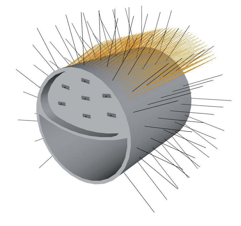
DAUB                         Digital Design, Building and Operation of Underground Structures – Model Requirements – Part 1

Digital Design, Building and Operation of Underground Structures. BIM in Tunnelling
Model requirements – Part 1: Object definition, coding and properties
Supplement to DAUB Recommendation BIM in Tunnelling (2019)

Publisher
Deutscher Ausschuss für unterirdisches Bauen e. V. (DAUB)
German Tunnelling Committee (ITA-AITES)
Mathias-Brüggen-Str. 41, 50827 Cologne, Germany
Tel. +49 - 221 - 5 97 95-0
Fax +49 - 221 - 5 97 95-50
E-Mail: info@daub.de
www.daub-ita.de

Prepared by the working group „BiT-Objektinformation“ within the working group „BIM im Tunnelbau“

Members of the working group:

Dr.-Ing. Frank Abel				                            HOCHTIEF Infrastructure GmbH
Dipl.-Ing. Lars Babendererde			                    BabEng GmbH
Dipl.-Ing. Sascha Boxheimer			                     Wayss & Freytag Ingenieurbau AG
Wolfgang Braunert				                              Implenia Construction GmbH
Dipl.-Ing. ETH Heinz Ehrbar			                     DB Netz AG
Dipl.-Ing. Wolfgang Fentzloff			                   Implenia Construction GmbH
Dr. Stefan Franz					DEGES GmbH
Dipl.-Ing. Stephan Frodl				                       Ed. Züblin AG
Dipl.-Bergbau-Ing. Stefan Gielchen (Gast)          Amberg Engineering AG
Thomas Honacker				                                PORR GmbH & Co. KGaA
Dipl.-Ing. Alexander Kropp			                      Max Bögl
Prof. Dr.-Ing. Roland Leucker (Layout + Druck)     Studiengesellschaft für Tunnel und Verkehrsanlagen e. V.
Dr.-Ing. Peter-Michael Mayer			                    Ed. Züblin AG
Carin Meißner					HOCHTIEF Infrastructure GmbH
M. Eng. Florian Riedel (Gast)			                   Drees & Sommer SE
M. Sc. Markus Scheffer (Gast)			                   SD Ingenieure GmbH
Dipl.-Ing. (FH) Zdravko Stojic			                  Alfred Kunz Untertagebau GmbH
Dr.-Ing. Thorsten Weiner			                        PORR GmbH & Co. KGaA
Dipl.-Ing. Andre Wesch				                         Implenia Construction GmbH
Dipl.-Ing. Markus Wessels			                       HOCHTIEF Infrastructure GmbH
Dipl.-Ing. Klaus Würthele			                       Ed. Züblin AG

November 2020
Digital Design, Building and Operation of Underground Structures – Model Requirements – Part 1                                                                         DAUB

Index
Preamble............................................................................. 55        Appendix 1 Object catalogue....................................... 17

1    Introduction�����������������������������������������������������������������5            Appendix 2 Examples of object coding.................... 17
    1.1      Starting situation������������������������������������������������������5         Appendix 3 Examples of properties and
    1.2      Scope of application and target audience�����5                                      attributes ................................................................... 17
    1.3      Distinction�������������������������������������������������������������������6
                                                                                                Appendix 3.1 Properties and attributes of object
2 Model structure�����������������������������������������������������������6                    group Temporary support .......................................... 17
     2.1     Coordination model������������������������������������������������6
     2.2     Discipline model�������������������������������������������������������6          Appendix 3.2 Properties and attributes of object
                                                                                                  group – permanent lining – concrete works........ 17
     2.3     Sub-models����������������������������������������������������������������6
     2.4     Object groups������������������������������������������������������������6        Appendix 3.2 Properties and attributes of object
     2.5     Object (element, equipment or space)������������7                                   group Excavation advance........................................... 17
     2.6     Sub-object������������������������������������������������������������������7
                                                                                                Appendix 4 Examples of visualisation....................... 17
3 Object catalogue��������������������������������������������������������� 7
     3.1 Description�����������������������������������������������������������������7
     3.2 Object coding����������������������������������������������������������� 8
             3.2.1      Level 010: Client������������������������������������������������10
             3.2.2      Level 020: Autor������������������������������������������������ 11
             3.2.3      Level 030: Project���������������������������������������������� 11
             3.2.4      Level 040: Part project������������������������������������ 12
             3.2.5      Level 050: Structure����������������������������������������� 12
             3.2.6      Level 060: Functionality���������������������������������� 12
             3.2.7      Level 070: Localisation������������������������������������ 12
             3.2.8      Level 080: Construction discipline������������� 12
             3.2.9      Level 090: Object group��������������������������������� 12
             3.2.10     Level 100: Object���������������������������������������������� 13
             3.2.11     Level 110: Sub-object�������������������������������������� 13
             3.2.12     Level 120: Identifier������������������������������������������ 13
             3.2.13     Level 130: Position 1 – Object���������������������� 13
             3.2.14     Level 140: Position 2 – Object���������������������� 14

4 Properties and attributes ��������������������������������������� 14

5 Outlook����������������������������������������������������������������������� 15

6 Glossary����������������������������������������������������������������������� 16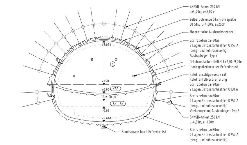
Digital Design, Building and Operation of Underground Structures – Model Requirements – Part 1 DAUB
Preamble
In order to ensure sustainable use of the many sources of information in infrastructure construction, it is
necessary that attention is also paid to digitalisation in underground construction.
Recommendations of the German Tunnelling Committee DAUB normally provide „best practice“ solutions for
underground construction in the German-speaking countries. The DAUB recommendation „Digital Design,
Building and Operation of Underground Structures – BIM in Tunnelling“ published in May 2019 was produced
with the objective of providing a basic understanding of the application of BIM in tunnelling. Based on this
recommendation, a working group „BIM im Tunnelbau“ has now concerned itself with further differentiation
of the model requirements specifically for underground construction in order to standardise and homog-
enise the approaches developed on the first pilot projects. The present document explains a basic under-
standing of the model structure and should provide uniform descriptions for typical objects in tunnelling
and the associated object information. A basic structure for object coding is presented for the unambiguous
identification of individual objects in a project.
It is to be expected that this recommendation will be successively revised in the coming years to suit further
developed requirements.
The present document is the start of a process of fixing various aspects described in the recommendation
„Digital Design, Building and Operation of Underground Structures – BIM in Tunnelling“, which will be con-
tinued in further parts.
1 Introduction This results in the following tasks for the working
group:
1.1 Starting situation Creation of a basic understanding of the model
structure
In order to enable the implementation of BIM in tun-
nelling, the process needs to further established or Identical naming of objects independent of the au-
standardised. Nevertheless, the following basic re- thor
quirements can be stated for model creation in BIM Identification and definition of the object informa-
projects: tion (features and attributes)
Collection of the project basics
Distinct labelling of different objects with a defined
Linking of 3D models with the cost estimate (BOQ), object code to establish the relationship between
scheduling and other information and processes model and, for example, schedule or cost planning
(3D, 4D, 5D)
Necessity of a high level of detail with numerous
objects (construction elements and machines)
Furthermore, the resulting model structure with the
Need for the unambiguous assignment of objects object definitions and the associated features can be
to various processes and information used as the basis for the preparation of a standardi-
Compatibility of the models for information transfer, sed object-oriented bill of quantities.
independent of author
1.2 Scope of application and target
In order to meet the above basic requirements, the audience
appropriate structures and definitions have to be de-
veloped for each project in the various consultancies This recommendation is intended for all parties in-
and companies. On BIM projects, such structures are volved in underground construction. The fundamental
defined for each specific project in the BIM execution requirements presented within this document can be
plan (BEP). used in the planning and design of all underground
The objective of this recommendation is to provide construction works. It should already be applied con-
standardisation for the project structure and the de- sistently in the design phase. Continuous application
scriptions used. of this approach should then be consistently main-
tained and implemented through the approval phase,
November 2020 page 5 of 17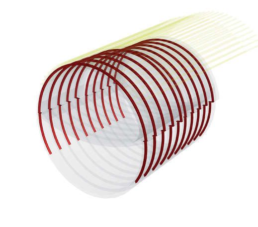
DAUB Digital Design, Building and Operation of Underground Structures – Model Requirements – Part 1
the tendering process, the construction phase and 2.3 Sub-models
later, during the operating phase.
The sub-model forms a defined part of the model of
1.3 Distinction the specialist designer and is geo-referenced to the
discipline model. Splitting of a discipline model into
The different activities involved in underground con- sub-models is only necessary when demanded by
struction depend on the intended use and construc- requirements or size of the project. It is also advisa-
tion process of the respective project. There are very ble to use sub-models for the design of intermediate
often interfaces to structural and special foundation construction states, e.g. the TBM arrival into a shaft.
engineering, buildings, road works, railway construc-
tion and tunnel installations. In order to provide a 2.4 Object groups
clear distinction, this document focuses on the un-
derground construction process in the design phase, An object group is a grouping of several objects,
during construction and later operation including the which leads to a final product from different assem-
necessary equipment and spaces. Interfaces to other bly processes.
disciplines are only shown schematically. One example of this would be the temporary shot-
crete support layer. The shotcrete layer is described
for the object coding (see Section 3.2) as „Primary
2 Model structure lining“ and contains the objects „Lining“, „Sealing
support“, „Reinforcement“, „Rock bolts“ and if neces-
The model is the basic tool for the application of sary further objects. Appendix 1 gives an overview
BIM and therefore has to be correctly formed, both
functionally and technically. Due to the wide variety
of construction projects, several consultants and con-
tractors are often involved in the modelling process.
In this section, the terms below are described as a
general overview.
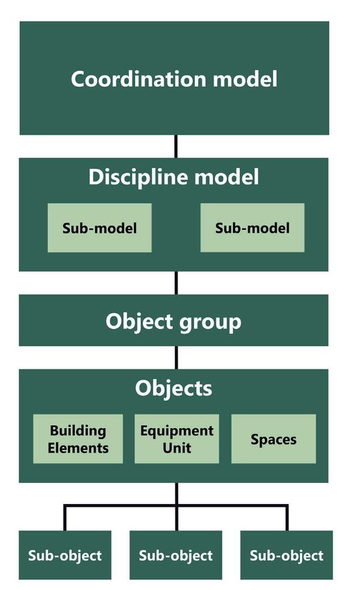
2.1 Coordination model
A coordination model (Figure 2.1) is a model assem-
bled from various discipline models for purposes of
design coordination. Due to the usual project scope
in underground construction, those models may rep-
resent project areas/sections or lots. One example
would be the coordination model „Tunnel“. By com-
bining the discipline models „Lining“ and „Drainage“,
for example, the levels for the drainage design can be
discussed at an early stage.
2.2 Discipline model
The discipline model contains specific information
from the single specialist designer in charge of their
discipline. Those designers involved in the project
create at least one discipline model, with the spa-
tial interfaces and project coordinates being agreed
among them. For underground construction, for ex-
ample, the discipline models tunnelling, lining, drain-
age or fire protection can be used.
In order to ensure clear structuring and for perfor-
mance reasons, it can be advantageous to divide the
discipline model into individual sub-models.
Figure 2.1 Modell structure
page 6 of 17 November 2020
Digital Design, Building and Operation of Underground Structures – Model Requirements – Part 1 DAUB
of the possible object groups under the heading „Ap- identification of (sub-) objects provides the model
pendix 1 - Object table“ in column „Level 090 – Object with the following capabilities.
group“. Filtering
Quantity take-off and calculations
2.5 Object (element, equipment or
space) Linking to activities from the construction schedule
(4D, construction progress simulations)
An object is an individual model element containing
stored information. It can be used to show the final Derivation of the bill of quantities (BOQ)
structure, fit out, temporary structures or equipment Linking with items or costs in the BOQ (5D, cost
for the construction process. curve)
Differing specifications for the description of an
object/element or equipment are common within the Implementation of target-actual comparisons
construction industry and in standards. Therefore, the Referencing of documents, photos, external data
DAUB recommends the following definition of terms, etc. to the relevant (sub-) object
which are also shown in Figure 2.1:
An Element is an object, which is necessary to rep- Amongst others, the two most important principles of
resent the completed state of the structure the BIM methodology are:
1) In order to avoid unnecessary information inter-
An Equipment Unit is an object, which is necessary
ruptions, the model serves as a „Single Source of
to construct the elements
Information“ through all project phases.
A Space is an immaterial object, which is assigned a
2) All project parties collaborate on the model.
function, e.g. a clearance profile, working space etc.
A precondition for the implementation of this appro-
2.6 Sub-object ach is a collaboratively defined model, which fits a ge-
nerally valid standard. Standardisation of the object
Sub-objects are mainly necessary for the design of catalogue is therefore essential and includes not only
detailed solutions. Sub-objects represent different the listing of the (sub-) objects but also their
parts of the object and thus show the inner quantities naming
of the object. The introduction of a sub-object is also
sometimes necessary to be able to continuously rep- name abbreviation
resent the generic, hierarchical structure. The object hierarchical structure and
„Rock bolts“, for example, can show the sub-objects
Rock bolt bar, Rock bolt mortar or Head plate. unique positional description
Experts from the DAUB working group „BIM im Tun-
3 Object catalogue nelbau“ (AK BiT) have therefore collaborated in order
to produce this fundamental basis. The collection of
3.1 Description the experts’ experience in modelling various underg-
round projects and intensive discussions result in the
The object catalogue is a structured collection of all object catalogue shown in Appendix 1.
objects and sub-objects necessary to model an un- The development of the object catalogue focuses
derground structure with relevant detailing. Appendix on the technical content that an object catalogue for
1 shows the object catalogue as a list with a hierarchi- underground construction should contain. The cata-
cal structure of 14 Levels. logue contains not only (sub-) objects, which pure-
The levels and the classification system for unam- ly relate to underground construction works. It also
biguous identification of the (sub-) objects are ex- includes related disciplines that commonly occur in
plained in Section 3.2. the course of the project developing and execution
As soon as the (sub-) objects have been modelled process.
as parameterised templates, they can be used for any Beginning with the familiar 2D drawings from un-
model in underground construction, with the relevant derground construction, the individual (sub-) objects
project-specific adaptations. The 3D model created are prepared, added to the catalogue, the hierarchical
in this way serves as the basis for further use-cases assignment defined, and a suitable name is given. In
based on the BIM methodology. The unambiguous order to illustrate this, an example of a tunnel exca-
vation with temporary support is shown in Figure 3.1
November 2020 page 7 of 17
DAUB Digital Design, Building and Operation of Underground Structures – Model Requirements – Part 1
to Figure 3.3, and an example of a permanent lining 3.2 Object coding
is shown in Figure 3.4 to Figure 3.6. Appendix 4 ro-
vides a collection of generic objects. Already in the early stages of the design phase of a
The object catalogue prepared as part of this rec- project, it is important to define a project structure
ommendation is available for download as an original that includes consideration of the object-based way
Excel file on the homepage of the DAUB. In this file, of thinking for the modelling that is suitable for the
assignments of the (sub-) objects are made in addi- intended use-cases. Particularly regarding 4D and 5D
tional columns so that filtering according to object functionality, it is also decisive to match the model
groups and their (sub-) objects is possible. structure and the individual objects, to the structure
Figure 3.1
Traditional detail
drawing of primary
support
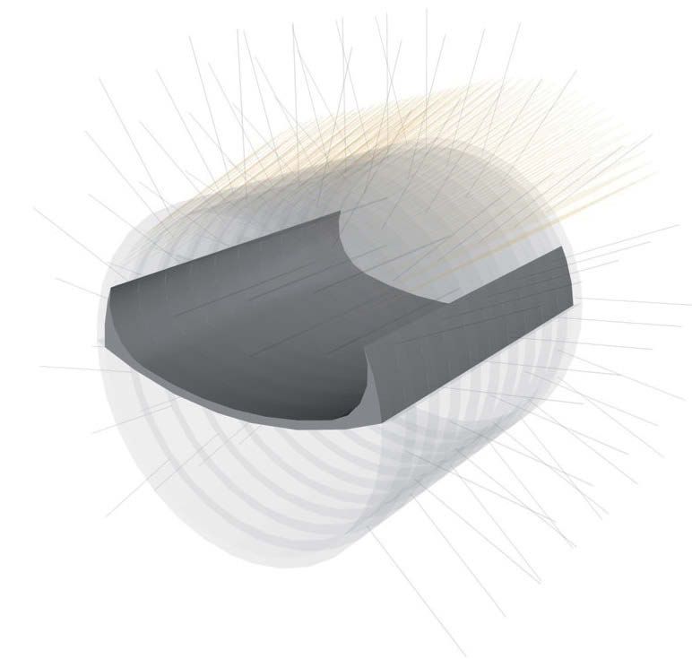
Figure 3.2
Illustration of
primary support in
the 3D model with
(sub-) objects
Figure 3.3
Example illustration of
the objects rock bolts,
steel ribsand lining
(top headinginvert/
shotcrete of the
primary support
in the 3D model
page 8 of 17 November 2020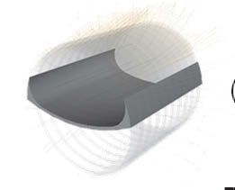
Digital Design, Building and Operation of Underground Structures – Model Requirements – Part 1                   DAUB

of the construction programme and the BOQ. So that                    This recommendation presents the results devel-
the (sub-) objects defined in the object catalogue can             oped by the DAUB working group from the previously
be uniquely identified within a project design and                 produced expert reports. In the formation of the ob-
thus enable a standardised and rule-based evaluation               ject coding, care was taken that the systems already
of the information in the model, it is necessary to as-            available on the market, like for example the StB Code
sign these a unique coding.                                        of the BIM working group in special foundation engi-

                                                                                                 Figure 3.4
                                                                                                 Traditional detail
                                                                                                 drawing of the
                                                                                                 permanent lining

                                                                                                 Figure 3.5
                                                                                                 Illustration of the
                                                                                                 permanent lining
                                                                                                 in the 3D model
                                                                                                 with objects and
                                                                                                 sub-objects

                                                                                                 Figure 3.6
                                                                                                 Example illustration
                                                                                                 of the objects invert,
                                                                                                 lining (concrete) and
                                                                                                 air duct slab of the
                                                                                                 permanent lining
                                                                                                 in the 3D model

November 2020                                                                                                  page 9 of 17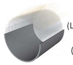
DAUB Digital Design, Building and Operation of Underground Structures – Model Requirements – Part 1
neering, could be integrated. The application of this 010 Client Figure 3.7
system is scalable due to its structure. Thus, the cod- Object coding
ing can be performed through the complete key or 020 Author structure
only a part of it. The diagram in Figure 3.7 shows the
structure of the system, which is explained in more 030 Project
detail below:
The first four levels (Level 010 to 040, green) of the 040 Sub-project
object catalogue (Client, Author, Project, Sub pro-
ject) define the main project information and assign 050 Structure
a responsible author to the modelled object.
060 Funtionality
The second section (Level 050 to 080, blue) de-
scribes the type, functionality and location of the
070 Localisation
associated structure and also defines the corre-
sponding specialist discipline.
Construction
The third section (Level 090 to 120, red) deals with 080
discipline
the actual objects. A unique definition of the mod-
elled object is activated by collecting the objects or 090 Object group
sub-objects into object groups and further localis-
ing them and making them identifiable through the
assignment of numbers.
100 Object
The final section (Level 130 and 140, grey) serves to
give the object a more detailed and final location
definition, which can be used to localise it.
110 Sub-object
Each of these levels has numerical or alphanumeri-
cal values or rather abbreviations with a predefined 120 Identifier
number of digits, which together form the object
code. Unassigned or missing information in the levels
130 Position 1 - Object
is filled with place holders (x). These place holders
should also be used when levels do not have to be or
140 Position 2 - Object
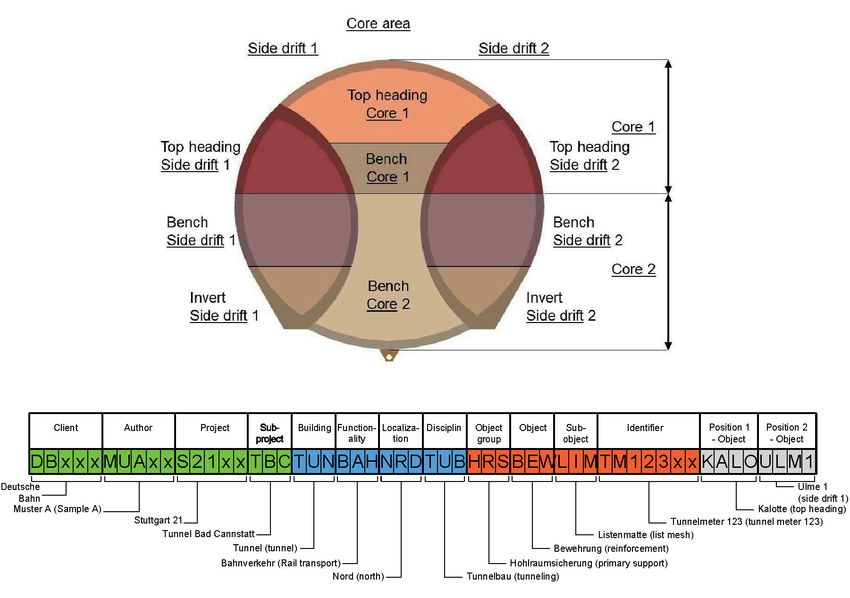
cannot be filled. Figure 3.8 provides an example to
clarify this: the code structure thus follows the proce-
dure „from coarse to fine“.
This code should be automatically created by the 3.2.1 Level 010: Client
relevant modelling program by input attributes. For In Level 010, information about the client is defined.
this purpose, on the one hand, basic project infor- Typically, there is only one client. On major projects,
mation can be used when creating the model. On the it is however possible that individual parts of the
other hand, entries can be made during the creation project have different clients. This Level enables as-
of the individual objects that are to be selected by signment of the models to the various clients. One
lists or freely defined. The object catalogue already example for this would be the major project Stuttgart
contains a large number of objects that can be used, 21 (S21), where the Deutsche Bahn (DB) awarded the
however this list is not exhaustive and should in the underground station and the Stuttgarter Straßenbah-
future be further expanded based on the experience nen (SSB) awarded the Staatsgalerie tram stop.
of the users. Level 010: Client
Default number of digits 5
Note for the English version: Proposal for automated General project
Abbreviations representing the naming of the sin- creation of the code information in the
gle levels and thus forming the object code are not segment model
translated into English. Example
Client Deutsche Bahn
Code segment DBxxx
page 10 of 17 November 2020Digital Design, Building and Operation of Underground Structures – Model Requirements – Part 1 DAUB
Figure 3.8 Example of object coding
3.2.2 Level 020: Autor 3.2.3 Level 030: Project
In order to clearly assign, monitor, and control the re- The naming of the project can be done in level 30. Ide-
sponsibility for model creation, the creator/author of ally, the abbreviation of the code should contain gen-
the model is specified in level 020. The details here erally valid abbreviations, as shown in the example.
should be company-related and not personalised.
Level 030: Project
Level 020: Author Default number of digits 5
Default number of digits 5
Proposal for automated
General project infor-
Proposal for automated General project creation of the code
mation in the model
creation of the code information in the segment
segment model Example
Example Project Stuttgart 21
Author Company Muster A
Code segment S21xx
Code segment MUAxx
November 2020 page 11 of 17DAUB Digital Design, Building and Operation of Underground Structures – Model Requirements – Part 1
3.2.4 Level 040: Part project 3.2.7 Level 070: Localisation
In Level 040, the main project is split into the indi- The process of localisation serves to further refine the
vidual sub-projects or construction lots. For example, defined location of the structure in order to perform
within this level the separate contracts „Zuführung a definite assignment of its location. For this purpose,
Bad Cannstatt“ or „Zuführung Feuerbach“ can be the Level 070 is available.
named as sub-projects of the main project S21.
Level 070: Localisation
This Level is only provided for use when required,
and for projects that are not divided this level should Default number of digits 3
be filled with placeholders („xxx“). Proposal for automated
selection list and/or
Level 040: Part project creation of the code
freely definable entry
segment
Default number of digits 3
Example
Proposal for automated general project
Localisation north
creation of the code information in the
segment model Code segment NRD
Example
Part project Tunnel Bad Cannstatt
Code segment TBC
3.2.5 Level 050: Structure 3.2.8 Level 080: Construction discipline
In Level 050, the project or sub- project is further bro- Differentiation of the construction disciplines in-
ken down. The breakdown is carried out in relation to volved in underground construction is undertaken in
the structures and covers all construction parts and Level 080. With this the object can also be assigned to
disciplines. The object is thus assigned to a structure. an individual discipline model.
Level 050: Structure Level 080: Construction discipline
Default number of digits 3 Default number of digits 3
Proposal for automated Proposal for automated
selection list and/or selection list and/or
creation of the code creation of the code
freely definable entry freely definable entry
segment segment
Example Example
Structure tunnel Construction discipline tunnelling
Code segment TUN Code segment TUB
3.2.6 Level 060: Functionality 3.2.9 Level 090: Object group
Level 060 can be used to further specify the individual The object group is a grouping of individual objects,
structures. The functionality of the structure can be which are assembled to form a completed product
described here if necessary. For example, a cavern through various assembly processes. Through level
could be assigned the functionality „Rail traffic“. 090, several objects (level 100) can be combined for
better evaluation or visualization.
Level 060: Functionality
Default number of digits 3 Level 090: Object group
Default number of digits 3
Proposal for automated
selection list and/or
creation of the code Proposal for automated
freely definable entry selection list and/or
segment creation of the code
freely definable entry
Example segment
Functionality rail traffic Example
Object group excavation support
Code segment BAH
Code segment HRS
page 12 of 17 November 2020Digital Design, Building and Operation of Underground Structures – Model Requirements – Part 1 DAUB
3.2.10 Level 100: Object 3.2.12 Level 120: Identifier
An object, which is defined in Level 100, is equivalent The identifier, which can be defined in Level 120,
to an element to be constructed or parts of the tun- serves to clearly differentiate between objects or to
nel fit out (see Section 2.5). The level of geometrical assign an object where there are many comparable
and informative detailing of the object is essentially objects, i.e. the block number of the inner concrete
dependent on the project specifications. In order to lining or the indication of the tunnel chainage. It also
make linking to the BOQ possible, it is recommended gives the spatial location along the tunnel. For the
to use the payment unit of the BOQ item as a guide- more precise differentiation of individual values, a
line. combination of letters and numbers is helpful, e.g.
The categorisation of the objects can also be per- „TM“ as an abbreviation for tunnel metre and „1234“
formed with consideration of the construction sched- to state the chainage.
ule, according to how the project structure plan is or-
Level 120: Identifier
ganised, and which uses cases have been specified.
The following Level 110 “Sub-object” serves for further Default number of digits 7
refinement. Proposal for automated
selection list and/or
Level 100: Object creation of the code
freely definable entry
segment
Default number of digits 3
Example
Proposal for automated
selection list and/or Identifier Tunnel metre
creation of the code
freely definable entry
segment
Code segment TM12345
Example
Object reinforcement
Code segment BEW
3.2.11 Level 110: Sub-object 3.2.13 Level 130: Position 1 – Object
A sub-object is the smallest element to be represent- The position of the object in the vertical sub-section is
ed in the model. In this Level 110, objects within ob- given in Level 130 in order to enable clearer identifi-
jects can be described, i.e. reinforcement in the per- cation of a specific position within the tunnel, e.g. top
manent lining. heading or bench.
If Level 100 is sufficient for the unique description
Level 130: Position 1 – Object
of objects, then this level remains „free“ and is filled
with the placeholder „xxx“. Default number of digits 4
Level 110: Sub-object Proposal for automated
selection list and/or
creation of the code
Default number of digits 3 freely definable entry
segment
Proposal for automated Example
selection list and/or
creation of the code
freely definable entry Position 1 – Object top heading
segment
Example Code segment KALO
Part object list mesh
Code segment LIM
November 2020 page 13 of 17DAUB Digital Design, Building and Operation of Underground Structures – Model Requirements – Part 1
3.2.14 Level 140: Position 2 – Object “value”, “unit”, “description in language N” or “naming
Level 140 can be used to provide further detail of the in language N”. The attributes available can be found
horizontal position in the sub-section of a certain el- in the standard mentioned above. Proposals for prop-
ement within a model and enable a clearer identifica- erties and the connected attributes “value range” and
tion of certain position, e.g. side wall 1, right or left, “unit” of the objects and/or subobjects are listed in
top or bottom. Appendix 3.
In the time being the working group is basically
Level 140: Position 2 – Object
revising the subject towards the use of a property
Default number of digits 4 data base. The release is planned for the 2nd Quarter
Proposal for automated in 2021.
selection list and/or Properties refer to objects or sub-objects, accord-
creation of the code
freely definable entry ing to which element in the hierarchy is modelled
segment
at the lowest level (level 100 or 110). This is closely
Example
bound to the relevant use-case or the relevant level
Position 2 – Object side wall 1 of detail (Figure 4.1). The following properties should
Code segment ULM1
be introduced for all objects and sub-objects:
A property for each code segment (see Section 3.2)
of the individual level
A property for the object code assembled from the
4 Properties and attributes code segments
The intended payment unit of the object or sub-ob-
Appendix 3 contains a list with proposed properties ject
and attributes for the (sub-) objects.
A property describes the characteristic of an ob- In the course of the development of in-house object
ject or sub-object and an attribute specifies this prop- samples, it is recommended as a minimum to consi-
erty. According to the standard DIN EN ISO 23386 der the properties of the object code and any further
each property may have one or more attributes, e.g. common properties of each object or sub-object.
Object Catalogue Property Catalogue
Lining
(Level 100: Object)
Intrados
(Level 110: Object part)
Round 1
(Level 120: Identifier) Type Shotcrete Layer
(Attribute)
Top Heading (Property)
(Level 130: Layer 1)
Material Shotcrete
Lining (Property)
(Attribute)
(Level 100: Object)
Intrados
(Level 110: Object part)
Advance 1
(Level 120: Identifier) Concrete C30/37 C35/45 C40/50
Top Heading Invert Grade (Attribute) (Attribute) (Attribute)
Primary Support (Level 130: Layer 1) (Property)
(Level 090: Object Group)
Lining Exposure XC1 XC2 XC3
(Level 100: Object) Class (Attribute) (Attribute) (Attribute)
Intrados (Property)
(Level 110: Object part)
Round 1
(Level 120: Identifier)
Invert
(Level 130: Layer 1)
Figure 4.1 Information in the object group primary support
page 14 of 17 November 2020Digital Design, Building and Operation of Underground Structures – Model Requirements – Part 1 DAUB
The objects or sub-objects listed in this docu- also be redefined by the client. These recommenda-
ment (see Appendix 1) describe, on the one hand, tions should serve as a basis for this.
elements or equipment specific to underground con- The subject of Geological modelling also de-
struction, but also describe elements, which are often mands further specification since this discipline is sig-
realised in connection with underground construction nificant for the sensible use of BIM in underground
projects (e.g. jet grout block). The properties and at- construction. The coding of the objects in the ground
tributes in Appendix 3 are only listed for the specific model should match the system presented here in or-
tunnelling objects and sub-objects. This list is a draft der to ensure continuous use of the model, especial-
and can serve as a sample for project specific selec- ly with regard to model-based payment and analysis.
tion or extension Collaborative management is the key to overcoming
the challenges resulting from contract arrangements
when it comes to geological risk allocation. It also
5 Outlook has to be said here that the ground model should
primarily reflect the geological report and the level
The objective of this first part of the Recommendation of detailing can only be as accurate as the site inves-
for Model Requirements was to create a uniform un- tigations it is based on. The use of a ground model
derstanding for a project/model structure, to define will however serve to improve project understanding
an object catalogue with consistent descriptions for and the evaluation of performance, thus, in turn also
objects and state a basic structure for the correspond- reduce risk. This application is to be seen as interdis-
ing properties and attributes. ciplinary and covers various project areas. Therefore,
Furthermore, some subjects have however not on complex projects, it cannot just be defined by the
been conclusively discussed and defined. For this pur- underground construction. The technical position pa-
pose, supplementary requirements (Model require- per „BIM im Spezialtiefbau“ (BIM in special foundation
ments – Part 2 et seqq.) are to be prepared. These engineering) of the German building industry associa-
should deal with the following subjects: tion already covers the subjects of digital soil models
Model types and digital terrain models. Due to the current limita-
tion regarding the practicality of 3D digital geological
Granularity modelling, closer attention should definitely be paid
Dealing with or consideration of pre-cambering, to this specialised area in the future in order to be
overbreak or tolerances in models for underground able to cover this use-case as well.
construction Activities of building SMART International (bSI) are
currently underway in the Infrastructure Room (IFC
Use-cases and their properties Tunnel). This may entail a revision of the classes of
Interoperability, data exchange the neutral data format IFC (Industry Foundation
Classes) in order to be able to represent and ex-
Coordinate systems change all objects and information for the special
Alignment dependencies needs of tunnelling.
In order that the system developed within this rec-
Model-/information-transfer scenarios ommendation can be put into use, the object cod-
… ing and the object catalogue including the proposed
properties and attributes will have to be integrated
The workings of the DAUB working group „BIM in into the software landscape. For this purpose, coordi-
Tunnelling“ are not final and still have to be proved nating activities are needed among all those involved
in practice. Experience, which will be gained in further including the software suppliers.
processing according to this recommendation, will All in all, it can be stated that this supplement to
be integrated in further supplements or revisions and the DAUB recommendation „BIM in Tunnelling“ rep-
published. resents the next major step towards standardisation
In the course of the further development of BIM of this design method in underground construction.
in tunnelling, it will also be important to develop a The publication of further parts of the model require-
standardised, object- and model-based Bill of Quan- ments, as described above, will ensure even great-
tities for underground construction. It will be tar- er clarity and understanding for all parties. This will
get-oriented and beneficial to all project parties if the further advance digitalisation in construction indus-
models are already created during the design phase try and ensure that clients and contractors can work
and made available to bidders and potential contrac- collaboratively in a spirit of partnership from the very
tors as a tender model in the tendering phase. The beginning to ensure the success of the project. ■
involvement of all parties in early project phases may
November 2020 page 15 of 17DAUB Digital Design, Building and Operation of Underground Structures – Model Requirements – Part 1
6 Glossary
Three-dimensional model of a structure containing physical, geometrical and func-
3D model
tional attributes
3D model, which is linked with the construction schedule or the construction acti-
4D model
vities through the component time.
5D model Extension of the 4D model to include cost planning
Employer Information Requirements (EIR); contract document, which specifies
AIA the information requirements of the client for tendering in order to lay down the
framework conditions for BIM application
Attribute Attributes specify the features of an object (according to DIN EN ISO 23386)
Tender model Model, which is made available by the client to all bidders in the tendering process
Use-case Special application using BIM methodology derived from the BIM aims
BIM execution plan; contract document, which explains the bidder’s plan for appli-
BEP cation of BIM and is cyclically developed during the course of the project, the level
of detailing (LoI, LoG and LoD) is also laid down here
Ground model Model with representation of the geological situation below ground
Building Information Modelling; BIM describes a cooperative working methodo-
logy based on the use of BIM models, which consistently record, administer the
BIM relevant information and data of a structure over its lifecycle and permit transpa-
rent communication and exchange between the contract parties or handover for
further processing
building SMART International; an international non-governmental non-profit orga-
bSI nisation; it defines the exchange format Industry Foundation Classes for BIM data
exchange in construction
Unique definition of an object through the assignment of numerical and alphanu-
Code
merical attributes; the overall code consists of the individual code segments
Part of the overall code, which defines the individual levels of the object catalogue
Code segment
proposed here
DACH Acronym for Germany (D), Austria (A) and Switzerland (CH)
Level of detail Describes the information content of digital 3D models (Level of Detail = LoD)
Geo-referenced Spatial assignment of an object in a coordinate system
Construction
In construction, this covers the works in a specialised field
discipline
Granularity Level of detail of the geometrical and semantics information
Industry Foundation Classes; manufacturer-independent, open, standardised and
IFC
object-oriented data format for exchange of models
Interoperability Compatibility of software systems with regard to data exchange without loss
Bill of quantities; tabular listing of work items to define the works to be underta-
BOQ
ken under a contract
page 16 of 17 November 2020Digital Design, Building and Operation of Underground Structures – Model Requirements – Part 1 DAUB
Defines the framework conditions for the creation of models to be observed in an
Modelling guideline
organisation or on a project
Definition of the structure of the individual part models and their relationship
Model structure
(Coordination model)
Project structure plan; categorises the overall extent of works in a project into
PSP
partial items and work packages
Appendix 1 Object catalogue
Appendix 2 Examples of object coding
Appendix 3 Examples of properties and attributes
Appendix 3.1 Properties and attributes of object group Temporary support
Appendix 3.2 Properties and attributes of object group – permanent lining – concrete works
Appendix 3.2 Properties and attributes of object group Excavation advance
Appendix 4 Examples of visualisation
The Appendixes listed above are available for download as compressed archives.
November 2020 page 17 of 17You can also read