Spectra RMS Molded Case Circuit Breakers - GE Consumer & Industrial Electrical Distribution - imagination at work
←
→
Page content transcription
If your browser does not render page correctly, please read the page content below
GE Consumer & Industrial
Electrical Distribution

                           ™
Spectra RMS
Molded Case Circuit Breakers

        imagination at work
Contents Pages Spectra RMS™ at a glance . . . . . . . . . . . . . . . . . . . . . . . . . . . . . . . . . . . . . . .1 Spectra RMS™ features and benefits overview . . . . . . . . . . . . . . . . . . . .3 Spectra RMS™ molded case circuit breakers . . . . . . . . . . . . . . . . . . . . . .6 Spectra RMS™ Mag-Break® motor circuit protectors . . . . . . . . . . . . . .8 Spectra RMS™ molded case switches . . . . . . . . . . . . . . . . . . . . . . . . . . .10 Accessories . . . . . . . . . . . . . . . . . . . . . . . . . . . . . . . . . . . . . . . . . . . . . . . . . . .12 Electrical data . . . . . . . . . . . . . . . . . . . . . . . . . . . . . . . . . . . . . . . . . . . . . . . . .19 Factors affecting current ratings of installed devices . . . . . . . . . . . .22 Interrupting ratings . . . . . . . . . . . . . . . . . . . . . . . . . . . . . . . . . . . . . . . . . . . .27 Spectra RMS™ trip unit . . . . . . . . . . . . . . . . . . . . . . . . . . . . . . . . . . . . . . . . .31 Physical data . . . . . . . . . . . . . . . . . . . . . . . . . . . . . . . . . . . . . . . . . . . . . . . . . .33 Outline drawings . . . . . . . . . . . . . . . . . . . . . . . . . . . . . . . . . . . . . . . . . . . . . .34 Guide Form Specifications . . . . . . . . . . . . . . . . . . . . . . . . . . . . . . . . . . . . .48
Spectra RMS™ at a glance
Characteristics
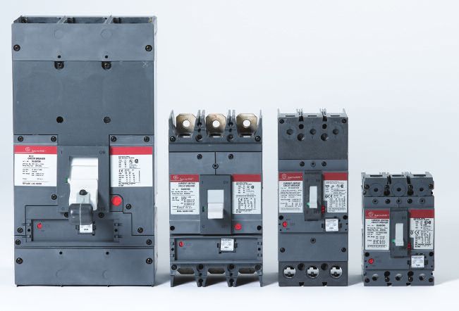
Spectra E Frame Spectra F Frame Spectra G Frame Spectra K Frame
SED SEH SEL SEP SFH SFL SFP SGD SGH SGL SGP SKH SKL SKP
Poles 2, 3① 2, 3① 2, 3① 2, 3①
Frame Rating (amperes) 150 250 600 1200
Current Range (amperes) 15 - 150② 70 - 250 125 - 600 300 - 1200
UL/CSA Rating 240Vac 18 65 100200 65 100 200 65 65 100 200 65 100 200
(kA RMS) 480Vac 18 25 65 100 35 65 100 – 35 65 100 50 65 100
(50/60 hz AC) 600Vac 14 18 25 25 22 25 25 – 25 65 65 25 42 65
Interrupting 220-240Vac
18/9③ 65/33③ 100/50③ 200/100③ 65/33 100/50 200/100 – 65/33 100/50 200/100 65/16 100/25 140/35
Ratings (Icu/Ics)
IEC 947-2 380-415Vac
Rating (50/60 14/7③ 35/17③ 65/33③ 100/50③ 35/17 65/33 100/50 – 25/13 65/33 100/50 50/13 65/16④ 85/25⑥
(Icu/Ics)
hz AC) 500Vac (Icu/Ics) 14/7③ 25/12③ 40/20③ 50/25③ 25/12 40/20 65/33 – 18/9 35/18 50/25 25/13 42/21⑤ 50/25
690Vac (Icu/Ics) – – 5/5③ 10/5③ – 14/7 18/9 – – 14/7 18/9 – 14/14 18/18
CE ✓ ✓ ✓ ✓
HACR ✓ ✓ ✓ ✓
Reverse Feed ✓ ✓ ✓ ✓
Ratings/ ✓
SWD (15 - 20A)
Markings
HID (15 - 50A) ✓
Current Limiting SEL, SEP SFL, SFP SGL, SGP
100% Rated SGH. SGL, SGP SKH. SKL, SKP
General Purpose (NEMA Type 1) ✓ ✓ ✓ ✓
Rain-Tight (NEMA Type 3R) ✓ ✓ ✓ ✓
Enclosures
Dust-Tight (NEMA Type 12) ✓ ✓ ✓ ✓
Water-Tight (NEMA Type 4/4X) ✓ ✓ ✓
A-Series (Main) ✓ ✓ ✓ ✓
A-Series (Branch) (AD) ✓
A-Series (Subfeed) (AD, AE) ✓ ✓
Panel ✓ ✓ ✓
Spectra (Main)
Connections
Spectra (Branch) ✓ ✓ ✓ ✓
SCP Plus (Branch) ✓ ✓
CCB (Branch) ✓ ✓
H 6.31 (160) 10.12 (257) 10.09 (256) 15.50 (394)
Dimensions
W 4.12 (105) 4.12 (105) 5.50 (140) 8.25 (210)
(inch/mm)
Envelope D 3.38 (86) 3.81 (97) 3.81 (97) 5.50 (140)
Weight (3 pole - max frame
5.65 9.15 15.85 47.6
rating) (lbs)
① 2 Pole Device in 3 Pole Frame
② SE MCP avail w/ 3 & 7 amp rating plugs
③ Spectra E Frame IEC ratings vary by ampere rating - consult table 31.1 for detail
④ 65/21 for SKL12
⑤ 42/16 for SKL12
⑥ 70/25 for SKP12
All frames are available as molded case circuit breakers, motor circuit protectors and molded case switches.
All frames accept the following common accessories and modifications:
• Shunt Trip • Mechanical Interlocks (3-pole)
• Undervoltage Trip • Handle Padlock Attachment
• Auxiliary Switches • Plug-in Base
• Bell Alarm Switch • Standard Lugs
• Motor Operator • Optional Lugs
• Handle Operators
1GE’s Spectra RMS™ circuit breaker line pioneered the use of interchangeable
rating plugs and universal internal accessories. With the superior performance
characteristics needed to meet your most demanding applications, rounded out
by a complete line of OEM accessories, we are confident that the Spectra RMS
line of circuit breakers, motor circuit protectors and molded case switches will
be the preferred product for most of your commercial, industrial and OEM
applications.
Snap-in Lugs
Universal Shunt Trip
Universal Undervoltage Release
Universal Auxiliary Contacts
Universal Bell Alarm Interchangeable Rating Plugs
• True RMS current sensing technology provides superior circuit protection. • Current limiting by design. Spectra SE, SF and SG frames provide excep-
The electronic trip unit accurately monitors and responds to overcurrent tional equipment protection with less system stressing.
conditions without the hassle of nuisance trips, even for non-sinusoidal • Front-mounted internal accessories and rating plugs make reverse feeding
loads such as SCR drives, welders, arc furnaces, computer power supplies possible on all frames.
and HID lighting. • Better packaging density delivers more amps per cubic inch. The Spectra
• Higher IC ratings. Ratings to 100kA@480V without fuses – and without SF Frame offers up to 250A protection and the Spectra G Frame up to
changing from traditional GE breaker sizes. 600A protection in a 4X wide frame, compared to the 6X wide J Frame.
2Spectra RMS™
Features and benefits overview
Interchangeable rating plugs
The ampere rating of the Spectra RMS™ family of circuit
breakers and MagBreak® motor circuit protectors is established
via an interchangeable rating plug located on the face of the
frame. To change the ampere rating, simply remove the
existing rating plug and “snap in” a new one (up to the maxi-
mum ampere rating of the frame). The unique accept/reject
feature prevents installing an incompatible rating plug. The
rating plugs are a fraction of the size of traditional thermal Table 3.1 Spectra RMS frame dimensions
magnetic replaceable trip units. A wide array of rating plugs Dimensions (in.)②
Frame Maximum Ampere
is offered for each frame size (see Table 5.1). H W D
SE 7, 30, 60, 100 & 150 6.31 4.12 3.38
Field-installed breaker accessories SF 250 10.12 4.12 3.81
Each Spectra RMS circuit breaker accepts a full range of SG 400 & 600 13.62① 5.50 3.81
internal accessories, including a wide array of shunt trip and SK 800 & 1200 15.50 8.25 5.50
undervoltage release devices as well as bell alarm and ① 10.49 without lugs.
② For detailed outlines, refer to pages 36-39.
auxiliary switches. These accessories are UL Listed for field
installation and install in minutes without the need to
remove the breaker cover. The best feature is that these Important space savings are built into each Spectra RMS
internal accessories are common across all frame sizes – a circuit breaker. Envelope dimensions for each frame are
simplified design approach that saves you time and money. shown in Table 3.1. Accessory leads exit from the right and
Fig. 3.1 Typical range of rating plugs SF Frame, Fig. 3.2 View of SG Frame breaker with accessory pouches open,
70-250 amps shown accessories displayed
3left sides of the breakers (see Figure 4.1). Each Spectra RMS In feeder circuit applications, the tracking short-time function
breaker has built-in channels along the sides and rear of the backs up downstream devices such as fuses or starter over-
frame to allow the accessory leads to lie below the surface loads with time for them to clear before the breaker opens.
of the frames (see Figure 4.2). No additional space is required For branch circuit applications, the Spectra RMS breaker pro-
between adjacent breakers to accommodates accessory vides added, tighter protection not available in any other
leads in group-mounted applications. The rear channel also standard 150-amp frame breaker.
allows accessory leads to be routed behind a panel-mount-
ed unit without the need for stand-off hardware. Higher interrupting capacities
Modern power distribution systems require protective
Application focused time-current characteristics devices with higher interrupting capacities. Each Spectra
The tracking short-time function provided by Spectra RMS RMS circuit breaker is available in multiple IC ranges with
circuit breakers is shown in Figure 4.3. Long-time and instanta- 100 kA rms symmetrical @ 480Vac being the maximum
neous-trip points establish the breaker’s full load and severe interrupting tier. Complete UL489, CSA C22.2, and IEC 947-2
overcurrent trip characteristics. interrupting ratings are detailed in Tables 28.1 and 29.1.
Fig. 4.1 View of typical breaker with undervoltage release leads brought
out on left side and auxiliary switch leads brought out on right side 1000
PICKUP
LONG TIME
DELAY
100
10 PICKUP
TRACKING SHORT TIME
TIME – SECONDS
7
5
4
DELAY
3
2
1
INSTANTANEOUS
.1
.01
.5 1 10 100 1000 10000
CURRENT – AMPERES x 10
Fig. 4.2 Undervoltage release leads run behind back of breaker Fig. 4.3 Typical time-current curve for Spectra RMS circuit breaker
4Spectra RMS Mag-Break product line Molded case switches, by definition, do not provide any over
The Spectra RMS Mag-Break motor circuit protector offers current protection. The short circuit withstand ratings are
the precision and ambient insensitivity of GE’s solid-state listed in Table 29.2.
tripping system in a highly cost-effective motor circuit pro-
Table. 5.1 Spectra RMS Circuit Breaker and Mag-Break motor circuit protector
tective device. The same interchangeable rating plugs are rating plug current ratings
used to define the instantaneous setting ranges of each Maximum
unit. The instantaneous-trip point and tracking short-time Frame Available Rating Plugs, Amperes
Amperes
characteristic is adjustable over approximately a 5-to-1 7① 3&7
range. Figure 5.1 illustrates time current curve features of the 30 15, 20, 25 & 30
typical Mag-Break unit shown in Figure 8.1. SE-Frame 60 40, 50 & 60
100 70, 80, 90 & 100
As an example of the flexibility of the Spectra RMS Mag-Break 150 110, 125 & 150
line, consider a 250A SF frame with 70A and 250A rating SF-Frame 250 70, 90, 100, 110, 125, 150, 175, 200, 225 & 250
plugs, the nominal instantaneous pickup range is 205 (min. 400 125, 150, 175, 200, 225, 250, 300, 350 & 400
SG-Frame
setting) to 700A (max. setting) with a 70A plug to a range of 600 250, 300, 350, 400, 450, 500 & 600
740A – 2500A with a 250A plug. (See Table 21.2 for details.) 800 300, 400, 500, 600, 700 & 800
SK-Frame
1,200 600, 700, 800, 900, 1000 & 1200
① The 7-amp frame and the 3A and 7A rating plugs are used only with the Spectra
Spectra RMS molded-case switch product line RMS Mag-Break motor circuit protector.
The Spectra RMS circuit breaker family also has a full line of
compact, economical circuit disconnect devices. Spectra RMS
molded case switches have seven current ratings from 100 Spectra RMS circuit breaker, Mag-Break and molded
amps to 1200 amps. In the event of mis-application or severe case switch product line
overcurrent, the contacts of these devices will open on a
non-adjustable, high-set, instantaneous basis, preventing Table. 5.2 Spectra RMS maximum frame ratings (amperes) &
damage to the molded case switch (see Table 10.1 for values). construction summary
Downstream conductor and load protection must be provided Motor Circuit Molded Case
Circuit Breaker①
Frame Protector② Switch③
by other devices with adequate interrupting capacity. (2 & 3 Pole)
(3 Pole Only) (3 Pole Only)
– 7 –
30 30 –
SE-Frame 60 60 –
100 100 100
150 150 150
SF-Frame 250 250 250
400 400 400
SG-Frame
600 600 600
1000 800 800 800
SK-Frame
1,200 1,200 1,200
TRACKING SHORT TIME ① Adjustable instantaneous/short-time with changeable long-time (via rating plug)
② Adjustable instantaneous/short-time
PICKUP
③ Fixed high-set instantaneous override
100
DELAY
10
TIME – SECONDS
1
INSTANTANEOUS
INST. set on MIN
INST. set on MAX
.1
.01
.5 1 10 100 1000 10000
CURRENT – AMPERES x 10
Fig. 5.1 Typical adjustability range for Spectra RMS Mag-Break motor circuit protector
5Spectra RMS™ molded case circuit breakers Trip unit characteristics
Spectra RMS circuit breakers offer the application flexibility and
accurate measurement of current waveforms with harmonic
Universal rating plug concept
content. In addition, SE-, SF- and SG-Frame circuit breakers
All Spectra RMS circuit breakers incorporate a UL Listed
incorporate true current limiting construction. All Spectra RMS
interchangeable rating plug that establishes the circuit
circuit breakers offer IC (Interrupting Capacity) ratings up to,
breaker’s ampere rating. The key advantages of the rating
and including 100,000 amps, rms, symmetrical, at 480 Vac
plug concept are the speed and flexibility of selecting or
and up to 200 kA at 240 Vac.
changing the ampere rating of the circuit breaker. Each circuit
breaker frame and sensor have multiple rating plugs that
offer a wide range of standard ampere ratings from which
Application flexibility
Application flexibility is provided by adding short-time and
to select.
instantaneous trip characteristics to the long-time, time current
curve of the solid-state trip system.
Since the installed rating plug establishes the ampere rating
of the breaker, the installer must verify the adequacy of the
connected cable and/or bus bar ampacity. The National
Long time
The rating plug determines the long-time trip performance of
Electrical Code allows cable size to be matched to the
the Spectra RMS circuit breaker. Spectra RMS circuit breakers
ampere rating established by the rating plug.
are designed to carry 100% of the rating plug ampere rating
continuously, in open air without exceeding a 50°C tempera-
All rating plugs have built-in accept/reject features to assure
ture rise at the circuit breaker terminals. At 105% to 130% of
that they are applied correctly. For example, SE-Frame Spectra
the rating plug ampere rating (the long-time pick-up tolerances
RMS circuit breakers are offered in four frame ratings: 30, 60,
of the trip circuit), the circuit breaker will trip in the event of a
100 and 150 amp. The 60-amp frame has three rating plugs
long-term overload downstream from the circuit breaker.
(40-, 50- and 60-amp). Rating plugs for the 60-amp SE-Frame
circuit breaker can only be used on that family of units.
Conversely, rating plugs for other frames or current ratings
Short time
The inverse-time short-time delay trip characteristic of Spectra
are not accepted by the 60-amp SE-Frame rating plug cavity.
RMS circuit breakers provides an increase in protection by
1000
LONG TIME
100
10
TIME – SECONDS
TRACKING SHORT TIME
1
INSTANTANEOUS
.1
.01
.5 1 10 100 1000 10000
CURRENT – AMPERES x 10
Fig. 6.1 Removal of rating plug Fig. 6.2 Typical adjustability range for Spectra RMS circuit breaker
6providing closer tracking of load-operating conditions. The When short circuit current flows through the lower and upper
short-time pickup function tracks the instantaneous pickup contact arms of the circuit breaker, a strong magnetic field is
by a factor of 0.5 to 0.8, depending upon specific frame and produced by the fault current. Since the fields are opposing,
rating plug. forces proportional to the square of the current act to “blow-
open” the movable contact arms. The higher the fault current,
Instantaneous the higher the contact separation forces. During maximum
The trip setting adjustment knob controls the settings of fault conditions, contact separation typically occurs within a
both short-time and instantaneous-trip characteristics. When quarter of one cycle, and the arc is fully quenched within
the adjustment knob is set in the “Max” position, the breaker eight milliseconds.
will trip instantaneously between 10 to 13 times (depending
upon breaker frame) the long-time trip rating (i.e., rating plug Peak let-through current, illustrated in Figure 7.2, is held to
amp rating). This provides sufficient margin to avoid nuisance less than 45% of the maximum available peak fault current,
tripping when energizing inductive loads such as motors or resulting in a tremendous reduction in the amount of energy
transformers. that the fault delivers to the conductors and the connected load.
The nominal instantaneous pickup values, in amps, are listed If current limiting performance is required, choose between
on each rating plug as shown in Figure 7.1. Spectra SEL, SEP, SFL, SFP, SGL and SGP catalog numbers.
Spectra RMS current limiting construction
Spectra RMS circuit breakers continue the GE standard of
rugged construction and the use of heavy silver-alloy contacts.
The low physical mass of the contact arms in the SE, SF and
SG Frame Spectra RMS circuit breakers, coupled with a
reverse current loop, result in true current limiting performance
without compromising breaker life.
Available Peak Current – 223.5 kA
Voltage – 485 V
Power Factor – 18.1%
Peak let thru – 37.7 kA
IA
1/2 cycle
IB
Peak let thru – 29.8 kA
IC
Peak let thru – 17.3 kA
Fig. 7.1 Rating plug label Fig. 7.2 Typical current limiting performance
7Spectra RMS™ Mag-Break® Spectra RMS Mag-Break trip unit characteristics
Spectra RMS Mag-Break motor circuit protectors provide
motor circuit protectors positive, reliable and cost-effective instantaneous, with
tracking short-time overcurrent protection to those circuits
Interchangeable rating plug where long-time overload protection is supplied by thermal
Spectra RMS Mag-Break motor circuit protectors use the or solid-state overload devices.
same snap-in rating plugs as fully configured (long-time trip
function) Spectra RMS circuit breakers. Each rating plug Motor circuit short circuit protection
defines the range of instantaneous-trip settings available to When a squirrel-cage induction motor is energized, a high
the circuit breaker through its trip setting adjustment. value of magnetizing inrush current flows for the first few
cycles, followed by a substantial reduction in current flow
Trip setting adjustment while the motor accelerates to its rated speed. When plotted
The solid-state instantaneous-trip circuitry of the Spectra on a time current curve, the motor current has three distinct
RMS Mag-break motor circuit protectors has a single, multi- regions – for the first five to eight cycles, typical magnetizing
position adjustment at the front of each breaker. Changes in inrush currents are approximately ten times the full-load
settings vary the instantaneous-trip and tracking short-time motor current (but can be much greater for high efficiency
characteristics. The Mag-Break motor circuit protectors differ motors). Between 0.10 and 10 seconds, the magnetizing
from a fully configured circuit breaker by only providing an inrush current drops to approximately five to six time the
instantaneous and tracking short-time trip function. full-load motor current. After approximately 10 seconds, the
motor reaches its full speed and the current quickly
Accessory pockets decreases to the full-load current of the motor.
Spectra RMS Mag-Break motor circuit protectors have the
same accessory pockets and use the same internal accessories Optimum motor protection for the first two regions of the
as Spectra RMS circuit breakers. This important capability motor time current plot would involve a two-tiered protection
allows field modification of Mag-Break units with shunt trip, scheme with a high value of current tolerated for a few
undervoltage release, bell alarm or auxiliary switch accessories, cycles, followed by a lower, sustained trip setting.
in any combination, without affecting the UL Listing status.
This is exactly the protection that is offered by the Mag-Break
Spectra RMS rating plugs motor circuit protector. This two tiered protection scheme
Use of the same UL Listed interchangeable rating plugs for prevents nuisance tripping due to magnetizing inrush current,
both Mag-Break and fully configured Spectra RMS circuit without compromising superior short circuit protection during
breakers expands the flexibility of the entire Spectra RMS motor acceleration. Protection for the third region of the motor
family of products. The advantages of interchangeable rating time current plot is accomplished via the motor starter’s
plugs with Spectra RMS circuit breakers are inherent to Spectra overload relay.
RMS Mag-Break units, which permit wider ranges of motor
ratings to be protected by a given breaker frame size. Figure 8.2 illustrates this motor protection scheme. Curve A
and the shaded area directly above it represents the region
1000
CURVE A
100
CURVE B
10
TIME – SECONDS
CURVE D
CURVE C
1
A – Motor damage
B – Motor overload
.1 C – Motor start
D – Mag-Break motor
circuit protector
.01
.5 10 100 1000 10000
CURRENT – AMPERES x 10
Fig. 8.1 SE150 Spectra RMS Mag-Break motor circuit protector Fig. 8.2 Motor circuit protection using Mag-Break motor circuit protectors
8of operation that will produce permanent damage to either
the motor, its feeder conductors or both. Curve B represents
the trip characteristics of the motor starter’s overload relay,
which provides both long-term overload and stall protection
but does not protect the system from short circuits in either
the motor or its feeder conductors. Curve C is a plot of the
motor current during a worst-case start (e.g., low line voltage,
highest load torque, etc.). Curve D represents the trip charac-
teristics of the Mag-Break motor circuit protector — with this
addition, the motor and its feeder conductors are now fully
protected against short circuits.
Spectra RMS Mag-Break motor circuit protector ratings
Table 9.1 lists rating plugs available for each Mag-Break
motor circuit protector frame size. Instantaneous trip settings
are listed under electrical data on page 21 and UL interrupting
ratings are shown on page 28 (per UL 489, motor circuit
protectors are not marked with interrupt ratings). Except for
3 amp and 7 amp plugs, all other rating plugs are used in
both circuit breaker and Mag-Break motor circuit protectors.
Table. 9.1 Spectra RMS Mag-Break motor circuit protector
and rating plug current ratings
Maximum Available Rating Plugs,
Frame
Amperes Amperes
7① 3&7
30 15, 20, 25 & 30
SE-Frame 60 40, 50 & 60
100 70, 80, 90 & 100
150 110, 125 & 150
SF-Frame 250 70, 90, 100, 110, 125, 150, 175, 200, 225 & 250
400 125, 150, 175, 200, 225, 250, 300, 350 & 400
SG-Frame
600 250, 300, 350, 400, 450, 500 & 600
800 300, 400, 500, 600, 700 & 800
SK-Frame
1,200 600, 700, 800, 900, 1000 & 1200
① The 7-amp frame and the 3A and 7A rating plugs are used only
with the Spectra RMS Mag-Break motor circuit protector.
9Table. 10.1 Spectra RMS molded case switch fixed trip setting
Spectra RMS™ molded case switches
Molded Case Maximum Fixed Trip Setting
Switch Frame Amperes RMS Amperes Nominal ±20%
Construction 100
SE-Frame 2,100
The family traditions of ruggedness and dependability are 150
continued in the Spectra RMS molded case switch line. These SF-Frame 250 2,450
units provide a circuit disconnect function using the compactness 400 5,600
SG-Frame
of molded case circuit breaker construction. The operating 600 6,000
handle actuates all three poles of the switch using the same 800 12,600
SK-Frame
internal components as the Spectra RMS circuit breakers 1,200 12,700
and Mag-Break units. The 7-amp frame and the 3A and 7A rating plugs are used only with the Spectra RMS
Mag-Break motor circuit protector.
Termination lugs
Snap-in termination lugs used with SE- and SF-Frame Spectra
RMS circuit breakers are used interchangeably in Spectra
Spectra RMS molded case switch applications
Molded case switches are inherently horsepower-rated. By
RMS molded case switches. SG- and SK-Frame molded case
virtue of the UL489 six-times-rated current overload test,
switches use the same bolt-on termination lugs used with
they can be used as motor circuit disconnects where
Spectra RMS circuit breakers.
overload and short circuit protection are provided by other
protective devices.
External accessories
The full range of external circuit breaker accessories offered
A common application of Spectra RMS molded case switches
for use with Spectra RMS circuit breakers and Mag-Break
is illustrated in Figure 10.2, which shows a system containing
motor circuit protectors, are available for molded case
three branch circuits.
switches. Figure 10.1 shows a Spectra RMS molded case
switch. In addition, plug-in bases, motor-operated mechanisms,
Branch Circuit 1 uses a Spectra RMS Mag-Break motor circuit
mechanical interlocks and the full complement of external
protector, in conjunction with the overload devices of the
handle operators (STDA, TDR and TDM) are available for use
motor starter, to protect the motor and the conductors of
with Spectra RMS molded case switches.
that branch circuit. Branch Circuits 2 and 3 use fully config-
ured Spectra RMS circuit breakers to provide instantaneous,
Fixed-trip setting
short-time and long-time protection for both branch-circuit
The Spectra RMS molded case switches are equipped with a
conductors and loads.
fixed Hi-set instantaneous trip setting whose values are
shown in Table 10.1.
Fig. 10.1 Spectra RMS molded case switch Fig. 10.2 Spectra RMS molded case application
10Protection of the short bus and feeder between the Spectra
RMS molded case switch and the bus in this figure is provid-
ed by a properly rated breaker.
Spectra RMS molded case switches are excellent circuit dis-
connect devices for those applications where both the
advantages of molded case switch construction are desired,
and where the available short circuit current is less than the
switch withstand rating as defined in Table 29.2.
All Spectra RMS molded case switches are UL Listed and
tested per UL Standard 1087 for molded case switches. The
short circuit withstand ratings are based upon three cycle
tests. Thus the UL Listed upstream overcurrent protective
devices (i.e., low-voltage power circuit breakers equipped
with instantaneous-trip functions, insulated-case circuit
breakers, molded case circuit breakers or fuses) can be used
in conjunction with molded case switches.
Table. 11.1 Spectra RMS molded case switch current ratings
Three-pole, 600-Vac
Switch Frame Type Maximum Frame Ampere
SE-Frame SEDA 100 & 150
SF-Frame SFDA 250
SG-Frame SGDA 400 & 600
SK-Frame SKDA 800 & 1200
11Accessories the bell alarm or aux switch in series could result in a 1 to 2
second delayed response if the breaker is re-closed while
the shunt trip is continuously energized.
Internal accessories
Spectra RMS™ internal accessories are common to all products
Electrical data
in the Spectra RMS product family, including circuit breakers, Table. 12.1 Shunt trip device electrical characteristics
Mag-Break motor circuit protectors and molded case switches. Catalog Rated Nominal Voltage Current, mA
They are interchangeable between frame sizes, i.e., the 24 Number AC DC Inrush Cont.
Vdc/24 Vac shunt trip – SAST3 – can be installed in any of the SAST1 120 125 500 6
four basic frames from the type SE150 to the type SK1200. SAST2 240 250 400 5
In addition, Spectra RMS internal accessories are designed SAST5 — 12 1000 800
to be installed in pockets accessible from the front of the SAST3 24 24 300 10
circuit breaker. SAST4 48 48 300 1
No disassembly of the circuit breaker case is required.
Black
These unique characteristics – interchangeability, commonality
and installation without violation of case integrity – provide
the user with the optimum combination of reliability, stan- Black
dardization and parts reduction. All Spectra RMS accessories
are UL Listed for field installation. Fig. 12.1 Wiring diagram, shunt trip
The left-hand circuit breaker accessory pocket accepts an
actuator, shunt trip or undervoltage release plus a bell alarm Undervoltage release
switch. The right-hand pocket is used for auxiliary switches.
All accessories are supplied with 36-inch long, #18AWG 105°C
300V minimum insulated leads. Side and rear wire channels
allow accessory leads to be led to the left, right or back of
the breaker within the dimensions of the breaker envelope.
Shunt trip
The undervoltage release trips the circuit breaker when control
voltage drops to less than 35% to 70% of its rated voltage.
Optional time delay units from 100 to 1,000 milliseconds
allow the user to minimize nuisance tripping. The time delay
may be switched off to provide an instantaneous undervoltage
trip. In the event an attempt is made to reclose the circuit
breaker while the undervoltage condition is still present, the
undervoltage release device will prevent breaker contact
closure; i.e., it’s a “kiss-free” design.
The shunt trip is used to trip (open) the circuit breaker by
remote control. Spectra RMS shunt trips are UL Listed for The “kiss-free” feature requires that if a breaker is in the OFF
field installation, meeting UL requirements for operation at position and the toggle handle is being held in the off position,
55% of rated ac voltage and 75% of rated dc voltage for use such as by a motor operated mechanism, and a trip command
on ground fault systems. from a shunt trip or undervoltage release (UVR) causes the
breaker mechanism to trip, the following steps must be
A momentary application of control power is recommended completed to turn on the breaker:
to activate the shunt trip coil. An integral pulsing circuit is 1. restore control power to UVR if applicable
used within the shunt trip’s electronics to prevent the coil 2. move toggle handle to ON position (breaker will not close)
from being damaged from maintained control power. If 3. move handle back to reset (OFF) position
maintained control power (latching relay) is used in lieu of 4. move handle to ON to close
momentary application of control power, use a bell alarm
contact in series with the shunt trip’s control power for the
SE/SF breakers or an auxiliary switch in series with the shunt
trip’s control power for the SG/SK breakers. Failure to wire
12Electrical data Yellow Yellow
Table. 13.1 Undervoltage release electrical characteristics
Catalog Rated Nominal Voltage Brown Brown
Peak Current, mA
Number AC DC
Purple Purple
SAUV1 120 125 200
SAUV2 240 250 200 Breaker Tripped Breaker On or Off
SAUV3 24 24 100 Fig. 13.2 Wiring diagram, bell alarm switch
SAUV4 48 48 100
Blue Auxiliary switch
Blue
Undervoltage Release
Fig. 13.1 Wiring diagram, undervoltage release
Actuator
All Spectra circuit breakers are supplied with a factory The auxiliary switch signals primary contact position (open
installed actuator in the left-side accessory pocket. The or closed) to other accessories (e.g., indicating lights, relays
actuator is removed when installing either a shunt trip or or logic circuits) for remote indication, interlocking and con-
undervoltage release. The catalog number for a replacement trol applications. Switch operation is independent of the
actuator is SACTUATOR. method used to open or close the breaker. Auxiliary switches
do not distinguish between a trip or open condition.
Bell alarm switch The auxiliary switch is available with either one or two single-
pole double-throw (SPDT) elements in either of two contact
ratings: control power duty contacts suitable for 120-240
Vac and 48-125 Vdc application, or low-impedance contacts
for signal-level circuits such as dc pilot circuits and pro-
grammable logic controllers. Signal-level contacts are gold-
plated and are suitable for 5-30 Vac or Vdc.
The bell alarm switch is used to signal breaker trip status to Electrical data
Table. 13.3 Auxiliary switch electrical characteristics
other accessories (e.g., external alarm devices, indicating
lights, relays or logic circuits) for remote indication and inter- Contact Ratings
locking applications. It is installed on the actuator or shunt Catalog Contact AC DC
Number Configuration Amps – Amps –
trip or undervoltage release. The switch operates when the Volts Amps Volts
Res. Ind.
breaker is tripped as a result of its protective functions, or as
SAUXPAB1 1 AB Element 120-240 5 48-125 0.50 0.25
the result of the operation of a shunt trip or undervoltage
release. The switch is not actuated as a result of normal SAUXPAB2 2 AB Elements 120-240 5 48-125 0.50 0.25
breaker “On-Off” operation. 1 AB Element,
SAUXGAB1 5-30 1 5-30 1.0 0.50
gold-plated
2 AB Elements,
The bell alarm switch is available with one single-pole double- SAUXGAB2
gold-plated
5-30 1 5-30 1.0 0.50
throw (SPDT) element in either of two ratings: with control
power duty contacts suitable for 120-240 Vac and 48-125
Vdc application, or low-impedance contacts for signal-level Red Orange
circuits such as dc pilot circuits and programmable logic
White Gray
controllers. Signal-level contacts are gold-plated and are
suitable for 5-30 Vac or Vdc. Brown/White Orange/White
Electrical data Shown with breaker contacts open
Table. 13.2 Alarm switch electrical characteristics
Fig. 13.3 Wiring diagram for SAUXPAB2
Contact Ratings
Catalog Contact AC DC
Number Configuration Amps – Amps –
Volts Amps Volts
Res. Ind.
SABAP1 1 AB element 120-240 5 48-125 0.50 0.25
1 AB element,
SABAG1 5-30 1 5-30 1.0 0.50
gold-plated
13External accessories Back-connected studs
Back-connected studs are used in applications where cabling
Termination lugs or bussing behind the panel is required. A mounting sub-base
Termination lugs permit easy front connection of either cop- is provided that mates with the Spectra RMS circuit breaker or
per or aluminum-insulated conductors to the terminals of molded case switch and the studs. Each stud is of sufficient
Spectra RMS circuit breakers and molded case switches. length to accommodate panel thicknesses from 0.25 inches
(6mm) to one inch (25mm).
Figure 14.1 illustrates the snap-in lugs that are installed
without tools in SE- and SF-Frame Spectra RMS circuit
breakers and molded case switches.
Sizes and ratings
Termination lugs are designed and tested for use with con-
ductors sized on 75°C ampacity and insulated with 75°C
insulation (or higher). Table 14.1 lists the conductor ranges
Fig. 14.2 Back-connected studs
for these tinplated extruded-aluminum lugs and copper lugs.
Table. 14.1 Lug sizes and ratings for circuit breakers (including Mag-Break) and
molded case switches Sizes and ratings
Device
Catalog
(Qty) Wire Range (75°C Insulated Conductor) Table 14.2 lists the back-connected studs available for the
Frame No. Aluminum & complete line of Spectra RMS circuit breakers, including
Frame Copper
Amps Copper Clad
All Frames TCAL18 & Mag-Break devices and molded case switches. These studs
SE (1) #12 – 3/0 AWG (1) #12 – 3/0 AWG
(7A to 150A) TCAL18LV① are field-installed.
TCAL29 & (1) #8 AWG – 350 (1) #8 AWG – 350
SF 250
TCAL29LV① kcmil kcmil Table. 14.2 Back-connected line and load studs
TCLK265② (2) 2/0 – 500 kcmil (2) 2/0 – 500 kcmil
SG 400, 600 & or (1) #8 AWG - or (1) #6 AWG - Max. Length, Back of Device Short/ Catalog
Frame
TCLK365③ 600 kcmil 600 kcmil Amps Inches Millimeters Long Number
800 TCAL81 (3) 3/0 - 500 kcmil (3) 3/0 - 500 kcmil 2 25/32 70.6 Short TEF1
SK 50
1200④ TCAL125 (4) 250 - 500 kcmil (4) 250 - 500 kcmil 4 13/32 112.0 Long TEF2
All Frames SE
SE TC018 (1) #12 – 3/0 AWG — 3 13/32 86.5 Short TEF3
(7A to 150A) 150
(1) #8 AWG – 350 5 25/32 147.0 Long TEF4
SF 250 TC029 — 2 23/32 69.0 Short TFK1
kcmil
SF 250
TCOK265②, (2) 2/0 – 500 kcmil 5 31/32 151.5 Long TFK2
SG 400, 600 —
TCOK365 or (1) #8 - 600 kcmil 2 13/16 71.4 Short SGBCS1
SG 600
800 TC081A (3) 250 - 500 kcmil — 6 1/16 153.7 Long SGBCS2
SK
1,200 TC0125 (4) 350 - 500 kcmil — 800 5 1/2 139.7 — TKM11
SK
① Includes 1/4" male spade terminal for control wire termination using UL Listed 250 1,200 8 203.0 — TKM12
Series fully insulated receptacle connector
② TCLK265 & TCOK265 included qty (2) lugs
③ TCLK365 & TCOK365 included qty (3) lugs
④ Alternate 1200A lug for SK; TCAL124 (3) 350-700 kcmil CU/AL, and TCO124
(3) 350-700 kcmil CU
Fig. 14.1 Typical Snap-in Lug Fig. 14.2 Spectra RMS lugs
14Plug-in mounting bases Table. 15.1 Plug-in mounting base
Plug-in Mounting Bases, 2 Required per Breaker
Plug-in mounting bases provide the user with another option
Optional
for quick changeout of breaker and switch assemblies without Horizontal Stud Mounting Plate
Amp Breaker No. of Configurations Catalog
disturbing power connections. Two plug-in bases (one for Rating Type Poles Number
each terminal end) are required for each protective device. PD1 PD2 Catalog Number
150 SE150 3 SLS LSL TE13PD1,2 TMP1
An optional mounting plate is supplied at no additional 2 SOS LOL TF22PD1,2
250 SF250 TMP2
charge when ordered with a pair of mounting bases, and 3 SLS LSL TF23PD1,2
provides three important functions. The plate locates and SG400
600 3 SLS LSL SGPC1,2① SMP3
supports the line and load base assemblies, provides a SG600
800 SK1200 3 SLS LSL TK83PD1A,2A TMP4
convenient means to mount the entire assembly to a metal
1,200 SK1200 3 SLS LSL TK123PD1A,2A TMP4
structure and serves as a deadfront barrier.
① Vertical stud orientation.
Each plug-in base assembly contains all of the mounting
hardware necessary to mount the base to either end of the Motor-operated mechanisms (MOM)
circuit breaker or molded case switch. Electrical spacing The MOM function uses an ac or dc motor-driven mechanism
between adjacent terminals is provided by alternate long- to produce rapid closing or opening. No physical modification
short-long (LSL) or short-long-short (SLS) terminal assemblies. of the breaker or switch is needed to add the MOM. The MOM
Fully configured Spectra RMS circuit breakers are available operator slips over the operating handle of the circuit breaker
in two-pole configurations— with the center pole missing. or molded case switch. The MOM cover can be lifted to man-
Consequently, base assemblies for two-pole breakers are ually open or close the breaker or switch. Visual indication of
either short-open-short (SOS) or long-open-long (LOL). SE-, the “On-Off” status appears on the mechanism cover.
SF- and SK-Frames use horizontal studs (suffix PD1 or PD2), Face-mounted mechanical interlocks
while SG-Frames use vertical studs (suffix PC1 or PC2). Table Mechanical interlocks are available for all Spectra RMS circuit
15.1 lists the sizes and ratings of the plug-in base assemblies. breakers and molded case switches. The function of the
mechanical interlock is to positively assure that two adjacent
When breakers or switches are mounted side by side, it is devices in an assembly cannot both be in their “On” (i.e.,
important to plan for adjacent outside poles of the two closed) position at the same time. However, both devices can
devices to have a long-short or short-long configuration, be “Off” (i.e., open or tripped) at the same time.
so that adequate electrical spacing is provided between
adjacent devices. These interlocks are useful whenever control or safety
requirements dictate an either-or energized condition down-
stream of the two protective devices.
Fig. 15.1 Plug-in mounting base Fig. 15.2 Motor-operated mechanism for an SF-Frame Spectra RMS circuit breaker
15Table. 16.1 Mechanical interlock (face mounted) Handle mounting dimensions fit standard flanged enclosures
Adapter Kit Required when using
Spectra RMS
Face-mounted
handle operator (TDM) or motor
with depths from eight inches to 24 inches (203mm to 609mm).
Interlock
Breaker Type operator
Cat. No.
(order separately)
SE150, SF250 SEFFMI SEFFMIAK
SG600 SGFMI SGFMIAK①
SK1200 SKFMI SKFMIAK
① Compatible with motor operator only. SGFMI cannot be used with handle operator.
Table. 16.2 Motor-operated mechanisms, rating and electrical data
Operating Time
Control Power
Device Catalog Seconds Recommended
Frame Number Voltage Amps Opening Fuse
Closing
① Inrush Running Reset
120 Vac 10.5 5
SEMOM1 1 Amp
125 Vdc 13.5 4
Time Delay
SE SEMOM2 240 Vac 6.5 3 0.15 0.13
SEMOM8 24 Vdc 31 15.5 2 Amp
SEMOM9 48 Vdc 20 7 Time Delay
120 Vac 10.5 5 Fig. 16.1 Type STDA1 flange handle
SFMOM1 1 Amp
125 Vdc 13.5 4
Time Delay
SF SFMOM2 240 Vac 6.5 3 0.15 0.13
Two different handle lengths are provided. Type STDA1, 1X
SFMOM8 24 Vdc 31 15.5 2 Amp
Time Delay
handles have a nominal length of 6 inches (152mm) and
SFMOM9 48 Vdc 20 7
120 Vac 13.5 8.5
Types STDA2, 2X handles have a nominal length of 10 inches
SGMOM1 (254mm). Both flange handles are interchangeable and are
125 Vdc 13.5 4.5
240 Vac 6.5 3 satisfactory for use with all operating mechanisms.
SG SGMOM2 0.25 0.20
250 Vac 8 2.5
SGMOM8 24 Vdc 33 19.5 The advantage to using the longer Type STDA2 handle is the
SGMOM9 48 Vdc 22 8.5 reduction in the operating forces provided by the longer lever
SKMOM1
120 Vac 14 7.5 arm. Both handles permit use of up to three 3/16 to 5/16
125 Vdc 18 5 3 Amp inch (4.75mm to 7.94mm) diameter padlocks. Both handles
240 Vac 7 3.5 Time Delay
SKMOM2 are equipped with O-ring seals for oil-tight/dust-tight duty.
SK 250 Vac 8.5 2.5 0.30 0.20
8 Amp
SKMOM8 24 Vdc 50 30
Time Delay Variable depth operating mechanisms
SKMOM9 48 Vdc 32.5 15
3 Amp The operating mechanism consists of two primary components:
Time Delay a combination mounting plate and yoke, and a drive rod
① All ac control power may be either 50 Hz or 60 Hz. that connects the handle to the yoke mechanism.
The protective device is mounted on the plate, and the device’s
Handle operators
operating handle slips into a slot on the front of the yoke. The
Three different operating handles are available for use with
mounting plates have a spring-assist feature to assure positive
Spectra RMS circuit breakers and molded case switches:
“On-Off” operation. Yoke stops are included to prevent
STDA, TDM and TDR. Each provides its own unique function.
excessive wear of the operating handle of the circuit breaker
Types STDA and TDM are adjustable-depth operating handles.
or molded case switch.
Type TDR operating handles are rotary handles that connect
directly to the protective device and the operating handle
The standard drive rod is 3/8 inch (9.5mm) in diameter for SE
projects directly through the enclosure door.
and SF and 1/2 inch for SG and SK frames.
Type STDA flange handles, variable depth operating
The SK frame operating mechanism (SD0M6) requires a
mechanisms and accessories
unique flange handle, Cat. No. STDA3 pr STDA3X which
Type STDA handles (Figure 16.1) are designed to meet auto-
cannot be used with any other operating mechanism.
motive-duty specifications. They are NEMA 12/13 and NEMA
4/4X UL recognized components. These handles can be
Type STDA handle accessories
located on either the right-hand or left-hand flange of an
Four accessories are available for use with the STDA handle
enclosure and they are field-convertible for either position.
16operator. They are auxiliary contacts, a flange stiffener (and Handles
an extended drive rod), an extended drive stud and special TDM door-mounted handles accommodate up to three pad-
NEMA 12 vault-type sealing and interlocking door hardware. locks. There are two basic handle styles. Both TH1 and TH2
handles are designed for NEMA 1, 3R and 12 enclosures. TH2
Auxiliary contacts handles are longer than TH1 to provide more torque for SG- and
Auxiliary single-pole, double-throw (SPDT) and double-pole, SK-Frame devices. When NEMA 4 or 4X enclosures are required,
double-throw (DPDT) auxiliary contact kits are available for handle Cat. No. THCH45 is available (for all size devices).
either left-flange or right-flange mounting. These contacts
are actuated by the operating mechanism yoke. Operating mechanisms, including shafts
The Type TDM operating mechanism attaches to the face of
Flange stiffener and extended drive rod the Spectra RMS circuit breaker or molded case switch. As
When either the enclosure needs stiffening behind the oper- mentioned earlier, the protective device may be mounted
ating handle, or a drive rod longer than 16 inches is required, either vertically or horizontally. Shafts are cut by the user to
a special flange stiffener kit is available. The kit contains a the length required for the specific application.
3/8-inch (9.5mm) drive rod 22 inches (559mm) long which is
threaded and may be cut to any convenient length. Replacement handle gaskets
Replacement neoprene gaskets are available for the TDM
Extended drive stud handle operators. Order part number 788A742P3 for the
Extended drive stud provides additional room inside the TH1 operator (SE/SF breakers) and 788A742P4 for the TH2
enclosure by allowing a 1 5/16-inch (33mm) displacement of operator (SG/SK breakers).
the operating mechanism with respect to the handle.
Specifically, when the handle is mounted on the right-hand Type TDR integral handle mechanism
side of the enclosure, the operating mechanism is displaced Type TDR handles are designed for direct mounting to the
to the left by 1 5/16-inches with the extended drive stud Spectra RMS circuit breaker or molded case switch operating
installed. Conversely, when the handle is installed on the handle. A door ring on the handle projects through a mating
left-hand side, the operating mechanism is displaced 1 5/16- hole on the front of the enclosure door. Type TDR handles
inches to the right. (Note: not suitable with SK frame operating are suitable for use with shallow depth NEMA 1, NEMA 12 or
mechanisms, SDOM6.) NEMA 12K enclosures. Rotary motion of the handle opens or
closes the protective device.
Vault-type interlocking door hardware
Type TDV door hardware kits are available to permit inter- Figure 17.1 shows a Type TDR handle operator. Different
locking with a STDA handle. Kits are designed for doors handles are used for vertical and horizontal mounting of the
having a nominal depth of 3/4 inch (19mm). The interlocking protective device. An interlock kit is available to mate with
function requires use of a screwdriver to release interlocking the door ring of the type TDR handle and provides an inter-
and permit door opening. Normally, the flange handle and lock function between protective device and enclosure door.
operating mechanism cannot be placed in the “ON” (energized) Gasket kits are available to limit the intrusion of dust and dirt
position unless the enclosure door and door hardware is into the enclosure through the space between the door ring
closed. Kits are available for both NEMA 12/13 and NEMA on the protective device and the hole in the enclosure door.
4/4X applications. A gasket kit is required for NEMA 12 and NEMA 12K applica-
tions. Order part number SEFRGSK for SE/SF breakers,
When enclosure doors are 40 inches (1,016mm) long or SGRGSK for SG breakers and SKRGSK for SK breakers.
longer, a third point latch is recommended and available.
Type TDM door-mounted handles and variable depth
operating mechanisms
Type TDM handles and mechanisms are designed for door-
mounting of a rotary operating handle. Shafts of various
lengths connect directly to a sliding plate assembly that fits
over the “On-Off” handle of the Spectra RMS circuit breaker
or molded case switch. The rotary motion of the TDM handle
opens or closes the protective device.
Fig. 17.1 Type TDR integral handle mechanism
17Fig. 18.1 The Spectra RMS circuit breaker family
Table. 18.1 Internal and external accessories available for the Spectra RMS product line
Product Circuit Breakers Mag-Break CBs Molded Case Switches
Shunt Trip Yes Yes Yes
UV Release Yes Yes Yes
Internal Accessories
Bell Alarm Switch Yes Yes Yes
Auxiliary Switch Yes Yes Yes
Line & Load Lugs Yes Yes Yes
Back-Connected Studs Yes Yes Yes
Plug-in Bases Yes Yes Yes
Motor-Operated Mechaansim Yes Yes Yes
Mechanical Interlock Yes Yes Yes
External Accessories
Type TDA Yes Yes Yes
External Handles Type TDR Yes Yes Yes
Type TDM Yes Yes Yes
Handle Blocking Device ① Yes Yes Yes
Padlock Device Yes Yes Yes
① SE and SF frames only.
18Electrical data devices. However, Spectra RMS circuit breakers can be used
to provide motor overload and overcurrent protection for
branch circuits containing infrequently started induction or
Introduction
synchronous motors.
The Electrical Data section of this manual is intended to
assist those responsible for the selection and application of
Spectra RMS molded case circuit breakers meet UL Standard
circuit protective devices in making the proper choices of
489 covering “Branch Circuit and Service Circuit Breakers”;
Spectra RMS™ circuit breakers and molded case switches.
NEMA Standard AB-1 – Molded Case Circuit Breakers: IEC
Because Spectra RMS devices are true international products,
Standard 947-2, Circuit Breakers (Low-voltage Switchgear and
attention is given to the selection procedures associated
Controlgear) and applicable Canadian and Japanese
with American, Canadian and IEC Standards.
standards. All Spectra RMS molded case circuit breakers are
marked HACR Type.
Electrical Data is presented in a sequence that follows the
steps necessary to make the selection of the protective
UL Standard vs. 100% rated
device that matches system and equipment requirements.
Spectra RMS circuit breakers are classified as “standard-
rated” devices with optional 100% rated versions available
General
in the SG and SK frames. UL Standard 489 makes provisions
Molded case circuit breakers
for two categories of circuit breakers. “UL Standard-rated”
Molded case circuit breakers are circuit protective devices
and “UL 100% rated”. The basis for UL Standard-rated circuit
that perform two primary functions: 1) manual switching to
breakers is as follows:
open and close a circuit by means of a toggle handle; and 2)
Mounted in free air. Circuit breakers are tested to carry 100%
automatic opening of the circuit under short circuit and/or
of nameplate current rating, continuously, when mounted in
sustained overload conditions.
free air at 25°C (77°F) and cabled per Table 22.1. However,
they are not applied in this manner.
Functions
Mounted in an enclosure. Spectra RMS enclosed circuit
A circuit breaker inherently protects circuits during short circuit
breakers are rated to carry 100% of nameplate current rating,
and overload conditions by automatically opening its protected
intermittently (three hours, maximum) and 80% continuously
electrical circuit without the use of fuses. When the circuit
with the enclosure in a 25°C ambient and cabled per
breaker opens to clear a short circuit or a sustained overload
Table 22.1.
condition, its “toggle” handle moves to the “Tripped” position
Group-mounted. Group-mounted circuit breakers may require
(midway between “On” and “Off” positions), indicating the
derating of the circuit breakers and cable in room ambients
circuit breaker has automatically opened. Once the overload
other than 25°C and with cable other than listed in Table 22.1.
or short circuit has been corrected, the circuit breaker can
be closed by simply moving the toggle handle first into the
“100%” breakers will carry full rated current continuously,
“Reset” (fully “Off”) position and then into the “On” position.
enclosed, provided the enclosure meets minimum size and
ventilation requirements (if specified).
Circuit breaker advantages
There are several advantages to using circuit breakers as
IEC equivalent to UL Standard rated circuit breakers
protective devices. One key advantage to circuit breakers
IEC Standard 947-2 lists three current ratings: “conventional
over fusible elements is that an overcurrent on one pole of a
free air thermal current (Ith)”; “conventional enclosed thermal
multipole device actuates a common trip bar that trips all
current (Ithe)”; and “rated current (In).” IEC procedures call for
poles simultaneously. Consequently, “single phasing” a
an eight-hour test. Consequently, when a standard-rated
three-phase load is not possible when a circuit breaker
circuit breaker is mounted in free air at 25°C and with the
opens, while it is possible with fusible devices. Molded case
cabling of Table 22.1, the breaker’s conventional free air
circuit breakers utilize “trip-free” construction. A trip-free
thermal current may be considered to be 100% of nameplate
device is one that cannot be forced into the closed or “On”
current. Enclosed circuit breakers cabled per Table 22.1 and
position when a tripping action is present as the result of an
mounted in 25°C room ambient may be considered to have
abnormal condition. If an attempt is made to manually close
a conventional enclosed thermal current of 80% of nameplate
a circuit breaker’s toggle handle while an overcurrent condition
current. Group-mounted circuit breakers may require addi-
exists in the protected circuit, the circuit breaker will open,
tional derating to reflect actual room ambient and cabling.
even if the toggle handle is held in the “On” position.
Rated current (In) is equal to the free air thermal current (Ith)
Protective function – circuit breakers
and is the same as the rated current for circuit breakers
Spectra RMS circuit breakers are not intended to replace
described in the technical data of this publication. Specifically,
running overload, unbalanced voltage or special-purpose
rated current per UL489 and rated current per IEC947-2 are
protection provided by other motor-protective equipment
equivalent terms.
such as overload relays and motor-temperature sensing
19Molded case switches Standards and references
Molded case switches are used as circuit-disconnect devices Underwriters’ Laboratories
where overload and short circuit protection for the relevant Branch Circuit and Service Circuit Breakers; and UL Standard
circuit is provided by other devices. Because these switches 1087, Molded Case Switches. Underwriters Laboratories, Inc.,
are tested to meet a size-times rated current overload 333 Pfingsten Road, Northbrook, IL 60062.
requirement they are useful as disconnects in motor circuits National Electrical Manufacturers Association (NEMA)
and are horsepower rated. NEMA Standard AB-1, Molded Case Circuit Breakers. NEMA,
1300 North 17th Street, Suite 1752, Rosslyn, VA 22209.
Spectra RMS molded case switches are designed to meet
and are tested in accordance with UL Standard 1087, specif- Institute of Electrical and Electronics Engineers (IEEE)
ically covering molded case switches. IEEE Standard No. 45, Recommended Practices for Electrical
Installation on Shipboard. IEEE Service Center, 445 Hoes
Lane, Piscataway, NJ 08854.
National Electrical Code (NEC) NFPA 70
NFPA Headquarters, 1 Battery March Park, Quincy, MA 02169.
International Electrotechnical Commission (IEC)
IEC Standard 947-2, Low-Voltage Switchgear and
Controlgear, Part 2, Circuit Breakers. Bureau Central de la
Commission Electrotechnique Internationale, 3, Rue de
Varembé, 1211 Geneva 20, Switzerland.
Canadian Standards Association (CSA)
CSA Standard 22.2 No. 5, Service Entrance and Branch Circuit
Breakers. CSA International, 178 Rexdale Blvd.,
Toronto, ON, M9W 1R3 Canada.
Japanese Industries Standard (JISC)
JISC Standard 8370, Low Voltage Switchgear and
Controlgear, Circuit Breakers.
Verband Deutscher Electrotechniker (VDE)
(Association of German Electrical Engineers)
VDE Specification 0660, Low Voltage Switchgear and
Controlgear, Circuit Breakers.
Approved by the city of New York, Bureau of Electrical Control
20Current ratings of circuit breakers and Mag-Break
motor circuit protectors
Table. 21.1 Spectra RMS circuit breaker current ratings Table 21.2 Spectra RMS circuit breaker current ratings
SE-Frame circuit breakers SF-, SG- and SK-Frame breakers
Instantaneous Trip Settings, Nominal RMS Instantaneous Trip Settings, Nominal RMS Sym,
Max. Rating Max. Rating Amps
Sym, Amps
Frame Frame Plug Frame Frame Plug
Trip Setting Adjustment Position Trip Setting Adjustment Position
Amps Amps Amps Amps
Min. 2 3 4 5 6 Max. Min. 2 3 4 5 Max.
3 11 13 16 19 24 31 39 70 205 260 330 410 535 700
7① 90 265 335 425 530 690 900
7 22 27 35 43 56 71 90
100 295 375 470 590 765 1,000
15 43 55 69 86 111 143 182
110 325 410 520 650 845 1,100
20 58 74 93 116 151 196 254
30 125 370 465 570 740 960 1,250
25 73 93 117 147 193 253 332 SF 250
150 440 560 705 885 1,150 1,500
30 87 112 142 179 237 314 415
175 515 655 825 1,035 1,345 1,750
40 118 150 188 237 308 394 501
200 590 750 940 1,180 1,535 2,000
60 50 148 187 236 296 386 498 637
SE 225 665 840 1,050 1,330 1,730 2,250
60 178 224 284 355 464 604 777
250 740 935 1,180 1,480 1,920 2,500
70 206 261 329 411 534 684 863
125 380 480 620 765 990 1,275
80 236 299 377 472 614 787 999
100 150 455 575 740 920 1,185 1,530
90 267 338 426 532 694 892 1,138
175 530 670 865 1,070 1,385 1,785
100 297 376 475 593 775 998 1,280
200 605 765 990 1,225 1,580 2,040
110 328 415 524 654 857 1,105 1,426
400 225 680 860 1,115 1,375 1,780 2,295
150 125 374 474 598 745 979 1,265 1,640 250 755 955 1,235 1,530 1,975 2,550
150 450 570 720 897 1,181 1,528 1,991 300 905 1,145 1,480 1,835 2,370 3,060
① The 7 Amp frame and the 3A and 7A rating plugs are used only with the Spectra 350 1,060 1,340 1,730 2,140 2,765 3,570
RMS Mag-Break motor circuit protector. SG
400 1,210 1,530 1,980 2,445 3,160 4,080
250 765 965 1,215 1,500 1,960 2,530
300 915 1,155 1,455 1,800 2,355 3,035
350 1,070 1,350 1,700 2,100 2,745 3,545
600 400 1,220 1,540 1,940 2,400 3,135 4,050
450 1,375 1,735 2,185 2,695 3,530 4,555
500 1,525 1,925 2,425 2,995 3,920 5,060
600 1,830 2,310 2,910 3,595 4,705 6,075
300 940 1,150 1,445 1,795 2,375 3,015
400 1,255 1,535 1,930 2,395 3,165 4,015
500 1,570 1,915 2,410 2,990 3,955 5,020
800
600 1,875 2,290 2,895 3,610 4,740 6,195
700 2,155 2,665 3,375 4,240 5,525 7,420
800 2,440 3,035 3,860 4,875 6,305 8,705
SK
600 1,825 2,310 2,905 3,685 4,730 6,110
700 2,125 2,695 3,390 4,300 5,515 7,125
800 2,430 3,080 3,870 4,910 6,305 8,145
1,200
900 2,735 3,465 4,355 5,525 7,090 9,160
1,000 3,040 3,850 4,840 6,140 8,880 10,180
1,200 3,650 4,620 5,805 7,370 9,455 12,215
21You can also read