MPEG MEDIA ENABLERS FOR RICHER XR EXPERIENCES
←
→
Page content transcription
If your browser does not render page correctly, please read the page content below
MPEG MEDIA ENABLERS FOR RICHER XR EXPERIENCES

              E. Thomas1, E. Potetsianakis1, T. Stockhammer2, I. Bouazizi3,
                                     M-L. Champel4

                                 1TNO, The Netherlands,
                           2Qualcomm  Incorporated, Germany,
                             3Qualcomm Incorporated, USA,
                                    4Xiaomi, China

       ABSTRACT
       With the advent of immersive media applications, the requirements for the
       representation and the consumption of such content has dramatically
       increased. The ever-increasing size of the media asset combined with the
       stringent motion-to-photon latency requirement makes the equation of a
       high quality of experience for XR streaming services difficult to solve. The
       MPEG-I standards aim at facilitating the wide deployment of immersive
       applications. This paper describes part 13, Video Decoding Interface, and
       part 14, Scene Description for MPEG Media of MPEG-I which address
       decoder management and the virtual scene composition, respectively.
       These new parts intend to make complex media rendering operations and
       hardware resources management hidden from the application, hence
       lowering the barrier for XR application to become mainstream and
       accessible to XR experience developers and designers. Both parts are
       expected to be published by ISO at the end of 2021.

INTRODUCTION
Extended Reality (XR) is an umbrella term for immersive experiences that includes Virtual
Reality (VR), Mixed Reality (MR) and Augmented Reality (AR). These applications utilize
computationally demanding technologies such as 360-degree video, spatial audio, 3D
graphics, etc. In order to successfully combine these media technologies in power
constrained end-devices, strict synchronization of the representations and resource
allocation is paramount. Currently, this is achieved with tailored application-specific
solutions. In many cases, application developers do not have access to advanced hardware
resources, especially when it comes to real-time media in immersive experiences. In order
to enable interoperability and efficient usage of device resources, the Moving Picture
Experts Group (MPEG) is working on part 13 and part 14 of the ISO/IEC 23090 MPEG
Immersive (MPEG-I) standard, both expected to be published by ISO at the end of 2021.
MPEG-I consists of several parts, addressing different needs of XR systems. This paper
focuses thus on part 13, Video Decoding Interface (VDI) and part 14, Scene Description for
Immersive Media (SD).
VDI addresses the need for managing simultaneous decoding of video elementary streams
in an efficient and synchronised fashion. Simultaneous decoding is necessary due to the
large number of video and media assets required for immersive experiences (e.g. 360-
degree video, video-based point cloud objects, 2D video textures, etc.). In addition, some of
those assets may be encoded as a set of independent subparts of the content (e.g. tiles in
360 video tiled-streaming, components in video-based point clouds), and thus have to be
decoded separately and then combined together to obtain the final output of the decoding
process, which in turns is fed to the GPU for further rendering operations. As such, resource
allocation, synchronization and buffer management of the decoding resources are critical in
order to consume the content and meet the tight deadlines of viewport rendering refresh of
XR applications. VDI will enable the efficient management of the decoding instances and
offer to the XR applications an interface that will hide the underlying complexity of this
management.
SD targets the composition aspects of immersive applications. To enable XR experiences,
a virtual scene must be constructed by assembling a number of assets of different types.
Current scene descriptor formats do not efficiently support real-time media and/or scene
graph updates and/or interaction and other features essential for immersive XR applications.
The integration of MPEG media into existing scene description formats (e.g. glTF TM) is
specifically addressed by the MPEG-I SD specification.

INTERFACES FOR VIDEO DECODING PLATFORMS

The Conventional MPEG Video Decoding Model
MPEG has published standards that have been a formidable accelerator for the mass
distribution of digitally encoded media. MPEG standards range from compression, storage
and to more recently streaming formats such as MPEG-DASH. In April 1996, ISO published
the first edition of ISO/IEC 13818 part 1 Systems (1), a.k.a. MPEG-2 Systems, and the
seventh edition in June 2019.
This part of MPEG-2 defines the
model for processing and
decoding audio and video coded
representations         and    their
presentation in a synchronised
fashion. To this end, MPEG
experts defined the System
Target Decoder (STD) which is “a
hypothetical reference model of a
decoding process”, as shown in
                                       Figure 1 – Program stream System Target Decoder
Figure 1 for the STD program
                                                 (P-STD), from ISO/IEC 13818-1
stream variant.
As seen in Figure 1, the i-th byte of the input program stream arrives at time t(i). Based on
the elementary stream index n, the i-th byte is oriented to the pipeline associated with its
elementary stream. For each elementary stream n, a decoder Dn receives and decodes the
j-th access unit An(j) at time tdn(j). The decoded access unit constitutes the k-th presentation
unit Pn(k) which is then presented at time tpn(k).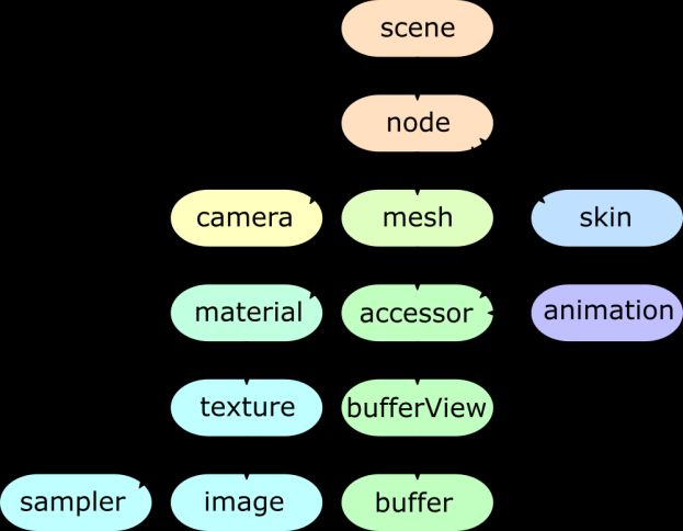
By defining the STDs (for both transport streams and program streams), a conventional
decoding model (CDM) has been established and was successfully used for several
decades. The rules governing this CDM are as follow:
i. Each elementary stream is decoded by one decoder instance, and thus:
a. Each video access unit has a given picture resolution
b. Each video access unit has a given chroma sampling
c. Each elementary stream has a given (variable) frame rate
ii. Each decoded access unit constitutes one presentation unit
iii. Each access unit is associated with a presentation timestamp via the corresponding
presentation unit referring to this access unit
New Video Decoding Needs of Immersive Streaming Applications
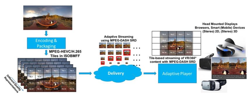
Viewport-dependent streaming
Streaming immersive applications are by essence event-driven and thus consume the media
representations in a dynamic fashion. These events can be the user’s head movement, the
user’s body translation, but also more traditional events for streaming applications such as
bandwidth variations. All these frequent events are factored in by the immersive applications
when retrieving the media content. The goal for the application is to maximise the quality of
experience perceived by the user. Since immersive applications render the view based on
the user viewport, the media content should also offer temporal and spatial random access.
This way, the application can retrieve the piece of data it needs for a particular viewport at
a particular time in the quality that is appropriate. In other words, immersive applications are
performing viewport-dependent rendering and thus there is an ongoing trend to design
viewport-dependent streaming logic such that the minimum amount of data is retrieved by
the application for the maximum quality perceived by the user. An example of such a system
is proposed by Graf et al (2) and reproduced in Figure 2 for streaming 360-degree videos
using tiles formatted and described according to MPEG-DASH and the SRD extension (3).
This flexibility in terms of what is retrieved means that the elementary streams that come out
of the encoders are generally not the input of the decoders in the application. Such
elementary streams are often manipulated and these bitstream manipulations should be as
lightweight as possible whether they are performed by media packagers, network entities or
by the application itself.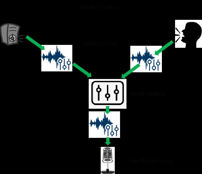
Figure 2 – System Architecture for Bandwidth Efficient Tiled Streaming (2)

Time alignment of independent video elementary streams after decoding
In some cases, an immersive experience comprises several independent media elementary
streams that all together form a visual object. For instance, MPEG has published the MPEG-
I part 5: Video-based point cloud compression (V-PCC) (3) which defines several video
components such as texture, geometry, occupancy, etc… which all together form the point
cloud after reconstruction. While each of these video components is independently coded,
there needs to be a synchronisation step, a time alignment operation, at the output of each
decoding process before all the decoded pictures can be used as input of the reconstruction
process of the point cloud. Figure 3 shows the different video components constituting the
coded point cloud as well the different input decoded sequences of the reconstruction
operations.

                         Figure 3 – V-PCC decoding structure (3)
While running several decoder instances on a video decoding platform is possible to the
extent the hardware can actually support it, there is no guarantee that these parallel
decoding instances would run in a synchronised fashion. On the contrary, implementing V-
PCC demonstrators in MPEG showed that some of the decoder instances run ahead or
behind of one another by several pictures. For example, the decoded texture picture of time
t is used with the decoded geometry picture of time t+dt. This slight desynchrony introduces
visual artefacts when performing the reconstruction operations of the point cloud with
various levels of severity depending on how large the desynchrony is and which components
are impacted.
Traditionally, the synchronisation of two video elementary streams is performed by the
presentation engine based on timestamps. Here, the need arises for the immersive
application to synchronise decoded pictures right after decoding based on their position in
the stream (also known as Picture Order Count in some video coding standards) and before
the presentation step at which the decoded data may be further synchronised based on
timestamps in the conventional way. These two types of synchronisation are not only
complementary but may also be sequentially needed given the type of application.
MPEG-I Video Decoding Interface (VDI)
Scope
MPEG-I VDI is the part 13 of MPEG-I published under the number ISO/IEC 23090-13 (5).
The aim of VDI is to address the problems and challenges when implementing immersive
applications as described in the paragraph “New Video Decoding Needs of Immersive
Streaming Applications”. To this end, the scope of the VDI specification covers the interface
between a media application and the Video Decoding Engine (VDE) sitting on the device as
shown in Figure 4.
A VDE as defined in VDI is the generic term corresponding to the application programming
interface (API) exposing the capacity of the video decoding hardware platform of the device.
Examples of VDIs are Khronos OpenMAX™ and the MediaSource Object of the Media
Application configuration and
capability query
Video Decoding Engine
Output Video Decoding Interface
Metadata stream #1 Metadata stream #1
Input Video Decoding Interface
… …
Metadata stream #m Metadata stream #p
Output formatting
Time locking
Video
Input formatting
decoder
instance #1
Elementary stream #1 Decoded sequence #1
…
… …
Video
Elementary stream #n Decoded sequence #q
decoder
instance #i
Figure 4 – Video Decoding Engine and interfacesSource Extensions W3C Recommendation (6). From the same VDE, several decoder
instances can be initiated. The purpose of the VDI specification is to provide to the
application a certain level of orchestration of these concurrently running decoding instances
via a set of functions, which are summarised in the paragraph “Operations and interfaces of
the VDI”.
Operations and interfaces of the VDI
The MPEG-I VDI specification Function Operation
defines new functions and operations queryCurrent Query the instantaneous
on top of the existing ones provided Aggregate aggregate capabilities of a
by the underlying VDI, e.g. Khronos Capabilities decoder platform for a
OpenMAX™. The list of new specific codec component.
functions defined by the VDI
getInstance Initiate a new decoding
specification as of May 2020 is
instance and optionally
provided in Table 1. The specification
assign it to a group of
is still under development and
existing instances.
additional functions are expected to
setConfig Configure a given instance
be added and refined before the final
in terms of output buffer
publication of the specification. The
properties
main benefit of these new functions is
getParameter Get dynamic parameters
that the application can not only
controlling a given instance,
spawn new decoding instances but
e.g. cropping window of the
can also group them into a group
decoded pictures
instance. This group instance would
share common properties and will be setParameter Set dynamic parameters
coordinated in such a way that the controlling a given instance
several instances share the e.g. cropping window of the
resources of VDE in a fair manner decoded pictures
and in the interest of the application Table 1 – Description of the VDI functions
and not compete against each other.
For instance, it should be avoided that one decoding instance would run ahead of another
in terms of number of pictures processed; which can cause visual artefacts in the final
rendering as presented earlier in this article.
In addition to these functions, new operations are also defined. As shown in Figure 4, the
different types of operations are input formatting, time locking and output formatting. The
draft specification as of May 2020 comprises four operations in the input formatting category,
namely filtering, inserting, appending and stacking. As explained in the paragraph “New
Video Decoding Needs of Immersive Streaming Applications”, it is fairly common for
immersive applications to produce content in parts, sometimes also called tiles. These tiles
are independently encoded and share the same encoding parameters. As a result, these
tiles can be indifferently decoded together as one video bitstream or in several video
bitstreams, one for each tile. However, merging them into a single video bitstream is a
tedious task for an application to perform since it requires rewriting and parsing of low-level
data in the video bitstreams. The level of complexity of this task varies based on the video
coding standard used for encoding the video elementary streams. Advantageously, the input
formatting module will allow the VDI to achieve this operation in lieu of the application. This
way, the number of incoming video elementary streams and the number of video decoderinstances to initiate can be decoupled and no longer follows a one-to-one mapping as described in paragraph “The Conventional MPEG Video Decoding Model”. Furthermore, the number of instances can be based on runtime optimisation decision and/or device capability discovery. For instance, a VDE may be able to decode one 4K video bitstream but not necessarily 4 HD video bitstreams simultaneously in which case merging them, if permitted by the bitstreams constraints, would allow their decoding. As hinted in this description, the input formatting module does expect certain constraints on the elementary streams, namely the video codec used and some constraints on the input video bitstreams. For that purpose, the VDI specification defines binding of the four input formatting operations with specific video codecs, namely with the Versatile Video Codec Coding (VVC) / H.266 (7) and expectedly with the High Efficiency Video Coding / H.265 (8) specifications. More codec bindings may be later added during the standardisation phase of the specification. Along with the specification, a sample library and a conformance software are being developed to validate the proper integration of the different modules of the VDI as well as the definition and constraints on the codec bindings. The publication of the VDI specification and the accompanying software is scheduled for 2021. SCENE DESCRIPTION Introduction to Scene Description Another key technology for enabling immersive 3D user experiences is scene description. Scene description is used to describe the composition of a 3D scene, referencing and positioning the different 2D and 3D assets in the scene. The information provided in the scene description is then used by a presentation engine to render the 3D scene properly, using techniques like Physically-Based Rendering (PBR) that produce realistic scenes. A scene description usually comprises a scene graph which is a directed acyclic graph, typically a plain tree-structure, that represents an object-based hierarchy of the geometry of a scene. The leaf nodes of the graph represent geometric primitives such as images, textures or media data buffers. Each node in the graph holds pointers to its children. The child nodes can among others be a group of other nodes, a geometry element, a transformation matrix, accessors to media data buffers, camera information for the rendering, etc. Spatial transformations are represented as nodes of the graph and represented by a transformation matrix. Typical usage of transform nodes is to describe rotation, translation or scaling of the objects in its child nodes. Scene graph also supports animation nodes that allow changes to animation properties over time, hence describing dynamic content. This structure of scene graphs has the advantage of reduced processing complexity, e.g. while traversing the graph for rendering. An example operation, that is simplified by the graph representation, is the culling operation where branches of the graph are dropped from processing, if deemed that the parent node’s space is not visible or relevant (level of detail culling) to the rendering of the current view frustum. While there are many proprietary solutions for scene description (typically at the heart of game engines, VFX design tools or AR/VR authoring tools), several solutions have also been standardized. In particular, Virtual Reality Modeling Language (VRML), which uses XML syntax, was the first scene description solution to be standardized in 2001 for WEB
usages. Later on, OpenSceneGraph, an open source project using OpenGL which was
released in 2005, has been used as a component in several computer games and rendering
platforms such as Delta3D or FlightGear. In 2010, X3D, standardized by ISO/IEC, became
the successor of VRML, introduced binary formats and JSON format for scene graph
description and featured new capabilities such as multi-texture rendering, shading, real-time
environment lightning, and culling. Finally, more recently in 2015, the Khronos Group, who
also manages OpenGL, released the Graphics Library Transmission Format (glTF). glTF is
a scene description format, based on a JSON format, intended to be efficient and
interoperable as a common description format for 3D content tools and services.
For its own scene description approach, MPEG decided to base its work on glTF as this
technology is already widely deployed and includes an extension mechanism. By working
on the definition of such extensions, MPEG can precisely focus on the shortcomings of the
current glTF solution with respect to MPEG media support and proposes its own solution as
an MPEG branded glTF extension.
A typical glTF scene graph is a tree of nodes describing content properties, access to
content data, possible dynamic animations and parameters for the rendering whose
relationship are shown in Figure 5. Typically, a camera node describes the view from which
rendering shall be made, 3D objects are described in mesh sub-nodes whose child nodes
provide information on how to access the
media data through buffers and texture
information, and animation nodes describe
dynamic changes of 3D objects over time.

MPEG Extensions to glTF 2.0
glTF 2.0 (9) provides a solid and efficient
baseline     for     exchangeable      and
interoperable scene descriptions. The
conceptual relationship between the top-
level elements of a glTF asset is given in
Figure 5. Traditionally, glTF 2.0 has been
focused on static scenes made of static
assets, which makes it unfit to address the        Figure 5 – Conceptual relationship
requirements and needs of dynamic and           between the top-level elements in glTF (9)
rich 3D scenes in immersive environments.
As part of its effort to define solutions for
immersive multimedia, MPEG has identified the following gaps in glTF 2.0:
   −   No support for timed media like video and moving meshes and point clouds.
   −   No support for audio.
   −   Limited support for interactions with the scene and the assets in the scene.
   −   No support for local and real-time media, which are crucial for example for AR
       experiences.
MPEG has decided to leverage the extension mechanism that glTF 2.0 offers, to develop its
solution for immersive multimedia after carefully evaluating different alternatives, including
home grown old scene graph solutions and the possibility of defining a new one from scratch.
In this section, we give a brief overview of the extensions that have been developed by
MPEG so far to address the identified gaps. MPEG developed an architecture for MPEG-I
to guide the work on the scene description, which serves as the entry point for consumption
of an immersive media presentation. Figure 6 depicts the MPEG-I architecture and defines
the key interfaces.
Figure 6 – Scene Description Reference Architecture
The design focuses mainly on buffers as means for data exchange throughout the media
access and rendering pipeline. It also defines a Media Access API to request media that is
referenced by the scene description, which will be made accessible through buffers. This
design aligns with glTF 2.0 principles and integrates with VDI presented earlier in this paper.
MPEG_timed_accessors extension
In order to provide access to timed media and metadata in a scene, a new glTF extension
is specified to define timed accessors. An accessor in glTF defines the types and layout of
the data as it is stored in a buffer that is viewed through a bufferView.
When timed data is read from a buffer, the data in the buffer is expected to change
dynamically with time. The buffer element is extended to add support for a circular buffer
that is used with timed data.MPEG_circular_buffer extension
The glTF 2.0 buffer element is extended to provide circular buffer functionality. The
extension is named MPEG_circular_buffer and may be included as part of the buffer
structures. Buffers that provide access to timed data must include the
MPEG_circular_buffer extension.
Frames of the buffer may differ in length based on the
amount of data for each frame. A read and a write pointer
are maintained for each circular buffer. By default, read and
write access to the buffer will be served from the frame that
is referenced by the read or write pointer respectively.
Access to a particular frame index or timestamp should be
supported.
The frames are read at the read pointer for rendering. New
incoming frames from the media decoder are inserted at
the write pointer. Prior data in that frame will be overwritten
and the frame buffer should be resized accordingly.
The renderer will always maintain that read operations are
performed on stored data and in an asynchronous way to
the write operations to the buffer. This will ensure that no
deadlock situations arise from simultaneous write
operations by the Media Access Function and the Figure 7 – Buffer structure
Presentation Engine.
MPEG_media extension and MPEG_video_texture
The MPEG media extension, identified by MPEG_media, provides an array of media items
used by different assets in the scene. This extension provides the necessary information to
make requests through the MAF API for media data.
MPEG video texture extension, identified by MPEG_video_texture, provides the
possibility to link a glTF texture object to a media
and its respective track listed by MPEG_media
object. The MPEG video texture extension
references a timed accessor, using the
timedAccessor object to receive the decoded
timed texture for rendering in form of a circular
buffer.
MPEG audio extension
The MPEG audio extension adds support for
spatialized audio to the MPEG scene description
based on glTF 2.0. This extension is identified by
MPEG_spatial_audio, which can be included
at top level or attached to any node in the scene.
The MPEG_spatial_audio extension supports
four different node types: Figure 8 – Processing chain for audio
in a scene− AudioSource: an audio source that provides input audio data into the scene
− AudioMixer: an audio mixer that mixes the output of one or more audio sources,
effects, and other mixers to produce an output audio signal.
− AudioEffect: An effect can be attached to the output of a source or a mixer or to
the input of an audio listener. It may also be standalone, in which case, it will apply
to all audio listeners that are in their active zone in the scene.
− AudioListener: An audio listener represents the output of audio in the scene. They
are usually attached to camera nodes in the scene.
The characteristics of AudioListener depend on the actual output devices available to
the audio renderer.
Scene Updates
In addition to the listed extensions, a Scene Update mechanism has been developed by
MPEG. The Scene Updates are expressed using the JSON Patch protocol as defined in
RFC 6902. Each update operation consists of a JSON Patch document, where all update
operations are considered as a single timed transaction. All update operations of a
transaction are executed successfully for an update operation to be considered successful.
After successfully performing an update operation, the resulting scene graph must remain
consistent, valid, and all references must be correct. Since glTF 2.0 uses the order of
elements for referencing, particular care is taken with update operations that change the
order of elements in the graph, such as move and remove operations. The client must
update all references after every successful scene update operation.
CONCLUSION
MPEG-I VDI and SD provide enablers for richer XR applications using MPEG media. The
combination of both specifications is expected to lower the barrier in terms of bandwidth and
latency requirements for streaming high quality XR experiences. Among other things, the
viewport-dependent streaming approach will be facilitated for XR applications by integrating
encapsulated MPEG media into existing scene description formats as well as enhancing the
video decoding platform APIs with interfaces to facilitate the management of multiple
concurrent video decoding instances. Both new MPEG specifications will offer software
conformance, test vectors and sample libraries for validating every step of the process of
properly integrating with the existing XR ecosystem. The publication of both specifications
is expected for end of 2021.
REFERENCES
1. ISO/IEC 13818-1:2019 Information technology — Generic coding of moving pictures and
associated audio information — Part 1: Systems. June, 2019.
2. Graf, M., Timmerer, C., and Mueller, C., 2017. Towards Bandwidth Efficient Adaptive
Streaming of Omnidirectional Video over HTTP: Design, Implementation, and Evaluation.
Proceedings of the 8th ACM on Multimedia Systems Conference (MMSys’17).
Association for Computing Machinery, New York, NY, USA, pp. 261 to pp. 271.3. D'Acunto, L., Van den Berg, J., Thomas, E., Niamut, O., 2016. Using MPEG DASH SRD for zoomable and navigable video. Proceedings of the 7th International Conference on Multimedia Systems. May, 2016. pp. 1 to 4. 4. ISO/IEC DIS 23090-5, Information technology — Coded representation of immersive media — Part 5: Video-based point cloud compression. October, 2019. 5. ISO/IEC WD 23090-13, Information technology — Coded representation of immersive media — Part 13: Video Decoding Interface for Immersive Media. February, 2020. 6. Media Source Extensions™, W3C Recommendation, 17 November 2016. 7. ISO/IEC DIS 23090-3, Information technology — Coded representation of immersive media — Part 3: Versatile video coding. November, 2019. 8. ISO/IEC FDIS 23008-2, Information technology — High efficiency coding and media delivery in heterogeneous environments — Part 2: High efficiency video coding, 4th edition. March, 2020 9. GL Transmission Format (glTF) Version 2.0. June, 2017
You can also read