New resilient bridge on liquefiable ground over the Ōpaoa River, Blenheim
←
→
Page content transcription
If your browser does not render page correctly, please read the page content below
Sensitivity: General

           New resilient bridge on liquefiable ground over
           the Ōpaoa River, Blenheim
           H.A. Hendrickson, G. J. Saul & P. Brabhaharan
           WSP, New Zealand.

           ABSTRACT
           A 190 m long, 2-lane bridge has been constructed over the Ōpaoa River on SH1, Blenheim. The
           bridge is in an area of high seismicity, and the site experienced liquefaction and lateral spreading in
           the 2016 Kaikōura earthquake. SH1 is a lifeline route and the bridge has been designed to
           importance level 3 to provide good resilience. The challenge was to achieve the expected resilience
           without adversely affecting the existing nearby heritage bridge structure which is to be preserved
           and used for walking and cycling.
           The key project objectives, put forward by Waka Kotahi New Zealand Transport Agency, were to
           provide a resilient structure, balance risks, protect the heritage values of the nearby existing bridge
           and provide high levels of performance.
           The design incorporates a zone of ground improvement by stone columns with a layer of high
           strength geotextile over top. Abutments are supported on driven h-piles and piers are founded on
           large diameter bored mono-piles.
           This paper presents a summary of the foundation options considered and the basis for selecting the
           adopted option. Options considered include combinations of bored or driven deep piles, ground
           improvements at abutments in the form of stone columns of various construction methods, deep soil
           mixing, soil replacement and continuous flight auger piles. Vertical reinforced earth walls and spill
           through abutments were both considered for the bridge approaches. The superstructure and span
           lengths were carefully designed to optimise performance.
           Key learnings and observations from the design and construction process are presented including
           verification of stone column ground improvement, design compromises made to improve safety in
           temporary works, verification of driven pile capacity and observations from construction of the pier
           foundations.

                                                              1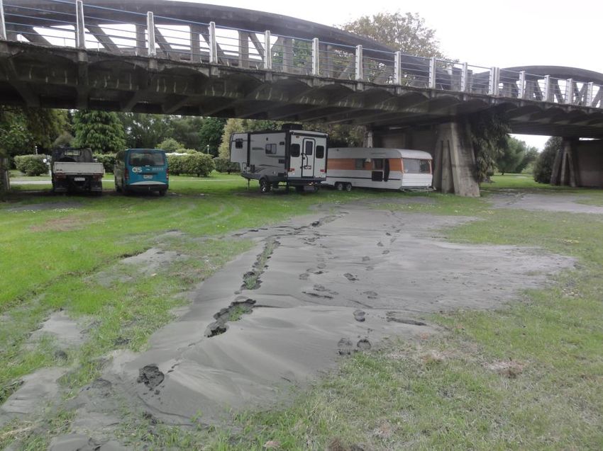
Sensitivity: General
1 INTRODUCTION
The pre-existing Opawa River Bridge (which is now a pedestrian and cycleway bridge) was located on State
Highway 1, just north of Blenheim. A seismic assessment of the bridge indicated that it has poor seismic
resilience during significant seismic events, narrow carriageway widths, poor geometric alignment and is
vulnerable to scour during flood events. A replacement bridge has been designed and constructed to modern
design standards and high levels of resilience.
This paper describes the design options considered, construction considerations and challenges.
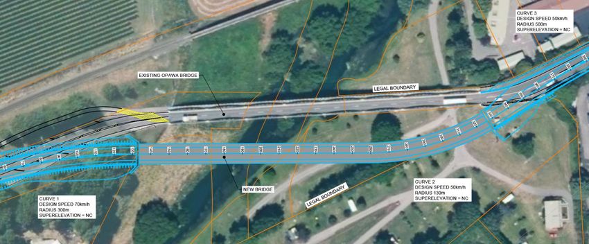
A plan of the site and proposed bridge alignment is shown in Figure 1.
Figure 1: Site Plan
2 PROJECT CHALLENGES AND OBJECTIVES
The previous bridge is a bow string arch type reinforced concrete structure constructed between 1915 and
1917, making it a category 1 heritage structure as defined by Heritage New Zealand. It was retained in place
as a pedestrian and cycling bridge. It is 170 m long and 5.49 m wide between kerbs which is significantly
below the Austroads minimum requirement of 7 m for a two-lane bridge. Traffic modelling shows poor
levels of service in both the morning and afternoon peaks, largely due to wide vehicles being unable to pass
each other when meeting head on. Furthermore, wide vehicles are required to cross the centreline which
poses safety risks to other road users and causes other traffic to have to slow down or stop.
The bridge is in an area of high seismicity, is of relatively heavy weight, and is vulnerable to damage in
seismic and flood events.
The objective of the design is to provide a replacement bridge with high levels of seismic resilience, amenity
and with geometrics and traffic safety designed to modern standards. The new bridge needs to address
challenges associated with the poor ground conditions and high seismicity while balancing constraints
associated with being adjacent to an existing heritage bridge, an alignment that runs through a campground,
and the environmental constraints associated with working alongside and over a river.
3 RESILIENCE
The 1915 arch bridge is located on State Highway 1 on the main national highway linking the North Island,
through the Wellington to Picton Ferry, to Christchurch in the South Island. Therefore, the resilience of this
bridge is of national significance. Locally, the bridge is immediately north of Blenheim town and if this
2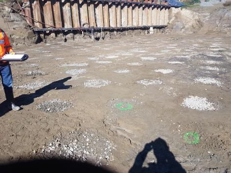
Sensitivity: General

           bridge is closed, the alternate reroute access would be along State Highways 62 and 63 through Spring
           Creek, Rapaura, Renwick and Woodbourne (which may themselves be also closed due to poor resilience of
           bridges) and would add over 30 km and 30 minutes to any journey. Although there are smaller local roads
           with narrower bridge crossings, these are unlikely to be suitable for heavy vehicles or they themselves would
           be vulnerable to damage in an earthquake event.
           The area is vulnerable to significant ground shaking and liquefaction due to the loose alluvial deposits
           present, and liquefaction and associated subsidence and lateral spreading is expected to affect the existing
           bridges pier and abutment foundations. A lack of restraint at the end bearings makes the existing bridge
           vulnerable to bridge span failure and movement of the heavy spans in the longitudinal direction causing
           shearing in the abutment piles.
           The 2016 magnitude 7.8 Kaikōura earthquake caused only low levels of ground shaking of about 0.25g in
           Blenheim, extensive liquefaction was observed at the bridge site and lateral spreading was limited given the
           low ground shaking, see Figure 2. In larger earthquakes, with higher ground shaking, greater liquefaction
           and lateral spreading can be expected which is expected to cause damage to the existing bridge.
           The flood resilience of the existing bridge is also very low with the centre pier of the bridge determined to be
           significantly comprised due to scour in a 1 in 100-year AEP flood.
           An earthquake or flood event could lead to compromise of the structural integrity and closure of the bridge.
           Replacement with a new bridge would take a long time, leading to poor resilience.

           Figure 2: Observed evidence of Liquefaction in the 2016 Kaikōura earthquake, with the old Opawa River
           bridge in the background

           The new bridge was designed to Importance Level 3 (IL3) of NZS 1170.5, and to the requirements of the
           Bridge Manual 3rd edition (NZTA, 2016) which was updated based on learnings from the 2010-2011
           Canterbury earthquake sequence (Wood et al, 2012). Early focus on resilience is important to achieve
           greater resilience for new infrastructure, and to avoid excessive cost (Brabhaharan, 2012), and therefore a
           key focus in developing design concepts was to select a bridge form and design concepts that would provide
           the level of resilience expected for the bridge.
                                                                  3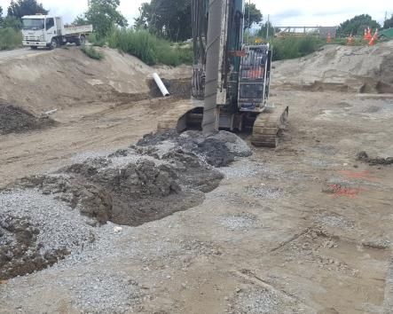
Sensitivity: General

           4      DEVELOPMENT OF DESIGN CONCEPTS
           Resilience was a key consideration in the development of design concepts and the selection of the bridge
           form. Lessons from damage to bridges in the Canterbury earthquakes in similar liquefaction conditions
           indicated that damage typically occurred to abutments and piers where they were positioned close to the river
           banks (Brabhaharan, 2012). Span arrangements were considered to minimise the numbers of piers close to
           river banks, and the design uses robust bored reinforced concrete piles for the piers, similar to those adopted
           for the Ferrymead bridge replacement after the earthquakes (Kirkcaldie et al, 2016). Ground improvement
           was adopted at the abutments to provide protection against liquefaction and reduce slope displacements. A
           piled abutment foundation was adopted to remove bridge loads from the embankment, further decreasing the
           potential for slope displacements.
           The final structural form that was adopted includes 30 m long single hollow core bridge beams founded on
           piers supported by 2.1 m diameter mono piles, see Figure 3. The bridge abutments are founded on driven H-
           pile foundations (10 per abutment) within a zone of ground improvement comprising stone columns and an
           overlying layer of high strength geotextile and a drainage blanket to help dissipate excess pore water
           pressures. The pier piles near the river banks were designed to resist the full crust load of lateral spreading,
           as the soils surrounding them are not treated with ground improvement. Cyclic ground displacements were
           also considered in design.
           The spans are simply supported at piers and abutments as this type of structure is more tolerant of potential
           vertical settlements in seismic cases compared to integral structural forms. The deck slab is continuous over
           the full length of the bridge with link slabs over the pier headstocks. The abutments are independent of the
           rest of the structure and the deck is free to translate in the longitudinal direction but restrained by shear keys
           in the transverse direction.

           Figure 3: Elevation of Bridge

           Shallow foundations for the piers were considered to offer low resilience as they would be vulnerable to
           scour, low bearing capacity in the surficial soils and unacceptably large settlements in seismic events where
           liquefaction occurs. Deep piled foundations can be designed to carry the large vertical loads and are resistant
           to many of the risks associated with shallow foundations. Due to the presence of cobbles and boulders in the
           intermediate gravel layers between 5 and 10 m depth (Unit 2) and the high levels of noise and vibration
           associated with driving the relatively large piles (or pile groups) that would be required to support the piers,
           large diameter bored piles were adopted at the bridge piers.

                                                                    4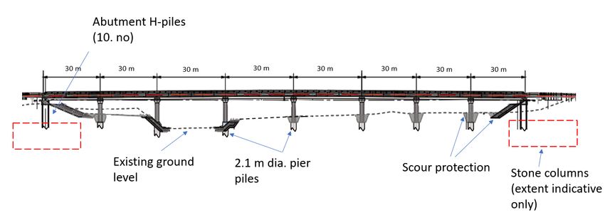
Sensitivity: General

           The pier piles are stiff structural elements compared to the abutments and therefore attract most of the
           longitudinal structural inertia loading. This leaves the H-piles and the abutments relatively lightly loaded and
           allows them to provide reinforcement to the approach embankments, should lateral spreading occur.
           Close interaction between geotechnical and structural engineers was required throughout all stages of design
           to ensure consistency in the seismic modelling, that the bridge structural form selected suited the ground
           condition and that the structure provided a high level of resilience.

           5      GROUND AND GROUNDWATER CONDITIONS
           Site investigations including boreholes, seismic shear wave velocity and standard cone penetrometer tests
           (CPTs) and laboratory testing were undertaken in two phases to characterise the site and support the various
           stages of design. Ground conditions at the site were found to include interbedded alluvial silts, sands and
           gravels underlain by very dense gravels of the Wairau Aquifer at 20 m depth. The silts were generally found
           to be non-plastic and in a soft to firm condition. The sands and gravels above 20 m depth were generally
           found to be very loose to medium dense with intermediate layers of very dense gravels.
           Hydrostatic groundwater was encountered at or near river level across the site and slightly artesian
           groundwater was encountered in the Wairau Aquifer.
           Potentially liquefiable soils include the non-plastic silts and loose and medium dense sands and gravels
           which are held in a sand matrix. Potentially liquefiable layers were identified at depths of up to 15 m below
           the water table level in Units 1 to 3 in Figure 4. The presence of liquefiable soils and the potential for lateral
           spreading at the site was confirmed during the 2016 Kaikōura earthquake where sand boils, ground
           subsidence and cracking were observed on site, see Figure 2.
           Geotechnical assessment during concept design identified potential for flow liquefaction at the margins of
           the river, with the potential for lateral spread in two directions at the southern abutment and in one direction
           at the northern abutment. Therefore, lateral spread was a critical consideration in design.
           An engineering geological section of the site is shown in Figure 4.

           Figure 4: Geological Section

                                                                    5
Sensitivity: General

           6      FOUNDATION CONCEPTS CONSIDERED
           Stability analysis of the new 6 m high approach fills and abutments with liquefied residual soil strengths in
           the underlying liquefiable soils confirmed that abutment instability can be expected in post liquefaction static
           cases and seismic vertical and lateral displacements which exceed the 50 mm limit set out in NZTA (2013).
           Mitigation was considered necessary to improve resilience of the structure and approach embankments in the
           vicinity of the abutments.
           A reinforced soil embankment and piled abutment were both considered for restraining abutment
           movements. A reinforced soil embankment is flexible and tolerant of large vertical and horizontal
           movements but would require ground improvement to achieve bearing capacity requirements. Due to the
           skewed alignment, structural loads do not act along the alignment of the bridge making it impossible for the
           abutment piles alone to resist the large soil loads. Therefore, ground improvements were adopted.
           Ground improvement options considered included; stone columns constructed by several different types of
           installation methods including soil replacement with stone or cement, deep soil mix columns and continuous
           flight auger piles in a grid or lattice layout. Due to the silty nature of the soils at the site, vibroflotation
           columns were considered unsuitable. Columns constructed using a steel casing which is then filled with
           stone and withdrawn as the aggregate is rammed into place or compacted with a displacement auger were
           considered most suited to the soil conditions. Stone columns also offered the advantage of lower costs and
           simpler construction when compared to other ground improvement methods considered.
           The stone column methodology adopted was McMillan Civils displacement auger method. This method is
           vibration free.
           Pile supported abutments with spill through embankments were adopted with a zone of stone column ground
           improvement at each abutment. The stone column target depths were optimised against potential slip
           surfaces and associated expected lateral displacements. Stone columns extend from approximately 1 m above
           water level to 10 m depth on the northern side and to 6 m depth on the southern side. They are overlain by
           300 mm thick drainage blankets with two orthogonal layers of high strength geofabric to restrain lateral
           ground movements, see Figure 5. The combination of vertical piles and ground improvement at the
           abutments provided the resilience requirements for this bridge and operational continuity requirements of the
           Bridge Manual and any damage would be readily repairable following a design level earthquake. The
           solution provides a high level of resilience for relatively moderate costs and was accepted by the Client as a
           prudent investment.

                                                                  6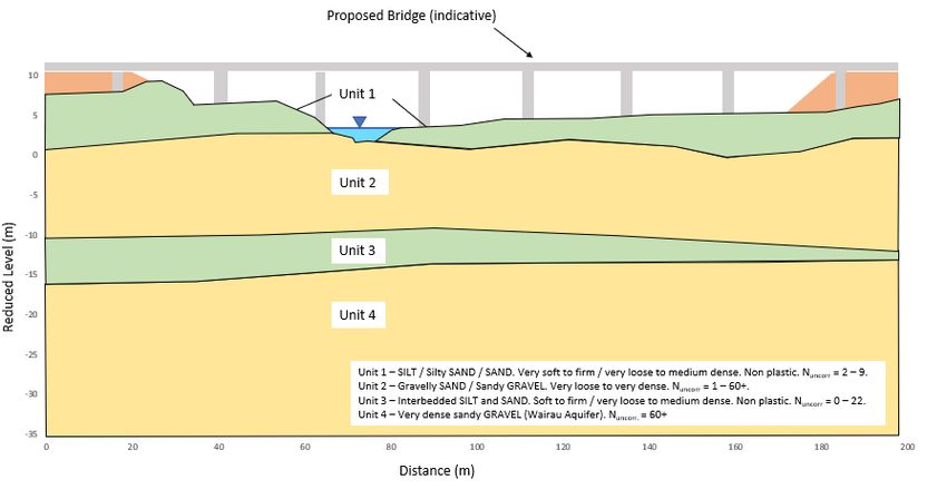
Sensitivity: General

           Figure 5: Section showing ground improvement and piles and the abutments

           7      DESIGN AND CONSTRUCTION

           7.1 Temporary Works
           In order to construct the high strength geotextile reinforcement at the required level, a temporary anchored
           sheet pile wall with a retained height of up to 4 m was required at both abutments. These walls supported the
           existing state highway which remained open throughout construction, and enabled the footprint and
           effectiveness of the zone of ground improvement to be maximised. The alignment of the sheet pile walls
           relative to the state highway had safety implications for the contractor and road users, with a tension between
           the design and construction related factors.
           The position of the temporary walling was negotiated and optimised during construction. Minor
           reconfiguration of the stone column zone was required including, shortening of some columns due to clashes
           with the gravel hopper for the stone column rig and the top of the wall, and repositioning of some columns
           to satisfy the needs of the design and improve safety onsite.

           7.2 Stone Column Ground Improvement
           7.2.1       Design
           Stone column ground improvement targeted improvement of the potentially liquefiable sands and silty sands
           of Unit 1 and the upper and liquefiable portion of unit 2 (refer to Figure 4).
           Extensive discussions regarding different ground improvement options were held through an early contractor
           involvement (ECI) process to ensure the best outcome for the project. Based on the ground condition
           information available and conditions onsite, non-vibratory displacement columns were adopted. The final
           stone column configuration involved a zone of 800 mm equivalent estimated diameter columns positioned at
           1.6 m centre to centre spacings on a staggered triangular grid layout. This resulted in an area replacement
           ratio of 29%.
           The expected levels of ground improvement for the stone columns were determined based on the outcomes
           of Christchurch based improvement projects that WSP had previously designed. The key findings which
           were used are summarised in Table 1.
           Table 1: Typical Ground Improvement Allowed for in Design
                                                                 7
Sensitivity: General
Typical Improvement in
Ic
qc (%)
< 2.0 80 – 120 %
2.0 – 2.6 20 - 40 %
> 2.6 No change
Our experience with this type of stone columns has been that post installation testing indicates significant
mitigation of ground subsidence but can indicate some silty soil layers could remain potentially liquefiable.
Allowance for some liquefaction between columns and associated lateral displacement was made in the
design. The abutment piles are designed for the associated increased lateral demand taking into
consideration the reinforcing effects of the H-piles on the embankment.
7.2.2 Ground Improvement Construction
Stone columns were constructed using a non-vibratory displacement auger method by specialist sub-
Contractor, McMillan Civil Ltd. A site-specific stone column trial was specified, constructed and tested
using CPT testing between columns and standard penetration testing down the columns, 35 days after
installation. Initially, the trial results showed levels of improvement and densification did not meet design
expectations in some layers. Possible reasons for this include the trial zone being too small to properly
confine the soils and the increase in lateral confining stresses, may have been relieved when the testing was
carried out too long after installation.
The trial was modified and repeated, and further verification testing was carried out, including cross hole
shear wave velocity across columns within the production stone columns. This indicated measured
improvements that aligned with design expectations. Verification CPT’s were positioned in the centre of the
triangular grids, on grid lines and immediately beside columns. Cone tip resistance increased closer to
columns, with some tests on grid lines and beside columns refusing on layers which were able to be
penetrated in the centre of the grid. A summary of the pre and post installation CPT tip resistances and shear
wave velocities are shown in Table 2.
The outcomes of the verification testing were compared to design expectations and the expected seismic
performance of the bridge was checked and found to be acceptable.
Table 2: Ground Improvement Summary
qc (MPa, before qc (MPa, after Vs (m/s post installation,
Unit Description Vs (m/s, pre installation)
installation) installation) measured across columns)
SILT / Silty
1 0.5 - 6 1-7 50 -120 150 - 234
SAND / SAND
Gravelly SAND
2 / Sandy 5 – 35 8 - 50 180 - 230 210 - 350
GRAVEL
8Sensitivity: General
Photographs of the stone column installation are shown below.
Photograph 1 - Displacement Auger
Photograph 2 – Installed columns showing heave around columns
Photograph 3: Completed columns showing sheet pile wall
7.2.3 Other Stone Column Construction Observations
Boreholes completed during the site investigations generally showed the ground on the northern side to
consist of interbedded hard and soft layers, while on the southern side, the soft layers were much thicker and
there were no hard layers within the depth range of stone column treatment.
Significant heave (up to 1 m3 per column) was observed on the northern abutment as stone columns were
installed but not at the southern abutment. On the northern side, heave began as soon as the auger penetrated
an intermediate hard layer and was observed to worsen as the auger penetrated and improved the hard layers.
Heave is not ideal as it represents a loss of improvement effectiveness. It is expected that the heave on the
northern side is due to the lateral confinement of the dense gravel layers (5 to 7 m depth) working against the
outward displacement effort of the stone column auger and forcing soil vertically up the outside of the auger.
The columns were constructed by first doing the perimeter columns then completing the remaining columns
in a spiral pattern towards the middle of the zone to maximise the ground improvement potential. Heave was
shown to increase towards the centre of the zone and is inferred to result from the increased horizontal
stresses and significant ground improvement.
7.3 Abutment Piles
The bridge abutments are supported on 10 no. 30 m long 310- H-piles driven into the very dense gravels
(Unit 4). Design pile bearing capacities were determined using Meyerhof’s method where the skin friction is
a function of the SPT N value and an ultimate end bearing capacity of 10 MPa was assumed based on the
piles being of low displacement type.
The required vertical ultimate pile capacity to be proven onsite was 1200 kN per pile and a geotechnical
strength reduction factor of 0.64 was adopted in design. Pile lengths were generally governed by the large
depths of liquefiable soils.
Pile vertical capacities were verified on site using pile dynamic analysis (PDA testing) during the final part
of the installation drive and the Hiley formula and subsequent CAPWAP analysis on 20 % of the piles. PDA
testing allowed for use of a higher geotechnical strength reduction factor for design and led to savings in pile
length. It also reduced uncertainty around the end bearing capacity, which is especially important given the
presence of liquefiable soils and associated potential for negative skin friction loads on the piles. The Hiley
formula was then calibrated using the CAPWAP results to verify the capacity of the remaining piles.
Values of maximum compressive stress and temporary pile compression measured during PDA testing
confirm driving conditions to be in the medium to hard range in accordance with ASG (2002).
9Sensitivity: General
The skin friction and end bearing capacities calculated in design and measured using pile dynamic analysis
are presented in Table 3 along with capacities calculated using the Hiley formula in accordance with AGS
(2002). Values are shown for piles which PDA analysis was undertaken only.
Table 3: Pile Capacity Summary
Design Values (Meyerhof) CAPWAP Outputs Hiley Capacity (ASG, 2002)
Qs Qb Qult Qs Qb Qult
Abutment Set (mm) R (kN)
(kN) (kN) (kN) (kN) (kN) (kN)
6.2 784 862 1646 1420
Southern 2064 961 3025
6.7 683 861 1544 1420
5.6 993 877 1870 1560
Northern 1666 961 2627
9 850 846 1696 963
The ultimate capacities calculated using traditional and recommended Hiley coefficients in accordance with
ASG (2002) give varying levels of conservatism compared to the CAPWAP analysis results. This is
considered to be due to conservatism built into the Hiley formula coefficients, given that it is a simplified
method of calculation and is therefore subject to a wide range of uncertainties.
It can also be seen from comparison of the Meyerhof design and CAPWAP analysis values presented in
Table 3, that the Meyerhof method used in design over predicted the pile shaft capacity but was close to the
end bearing capacity measured in the CAPWAP analysis. It also is possible the CAPWAP results reported in
Table 3 are low as the shaft capacity often increases with time following driving and is higher in subsequent
re-drives. A re-drive was not carried out on this project as all piles achieved the required capacity on initial
installation and testing.
When typical pile strength reduction factors are considered, a strength reduction factor of 0.5 applied to the
Meyerhof capacities and a factor of 0.64 applied to the CAPWAP outcomes, reduces the difference between
the two.
7.4 Pier Foundations
The bridge piers are founded on 2.1 m diameter, permanently cased bored piles founded in the very dense
gravels (Unit 4). The piles are designed to resist negative skin friction and have small settlements in seismic
cases.
Pile casings were installed using a combination of vibratory driving then hammer driving. Variation in
ground levels onsite meant casing lengths needed to be varied to keep pile tops above ground level during
construction. For simplicity, all casings supplied to site were the same length and were driven until the
required top of casing level was achieved. All of the casings except one were driven to below the required
founding level and a 0.5 m to 1 m long soil plug was left in place inside the casing following excavation.
The only exception to this were the piles in the water channel where the artesian head was observed to be the
highest. At the location of these piles, the contractor used a 1 m higher pile casing and this was sufficient to
prevent upward flow of groundwater causing softening of the pile base until the pile was poured.
Pile founding depths were verified by inspection of soil samples collected from 2 m depth intervals as the
excavation advanced and from the bottom of the pile. Drillers logs were also compared with borehole logs
from site investigation to ensure layers matched and adequate penetration into the founding layer had been
10Sensitivity: General
achieved. Pile cleanout was achieved by allowing the suspended soil in the fluid column to settle then using a
cleaning bucket to remove the loose sediments from the base. This was repeated until the cleaning bucket did
not pick up loose sediment. In addition to this, concrete was poured through a pressurised tremie, to scour
and displace any remaining loose sediments from the base of the hole.
8 CONCLUSIONS
The Ōpaoa River Bridge is in an area of high seismicity and is a geotechnically challenging site. Key
challenges included soft and liquefiable ground, lateral spreading and physical space constraints.
The replacement bridge was designed to provide a high level of seismic performance and resilience. Close
interaction between Structural and Geotechnical Engineers was essential throughout all phases of design and
was critical in achieving successful resilience in an economical manner.
Geotechnical models and analysis used in design are theoretical and testing during construction is limited
and constrained by the construction programme. Care needs to be exercised during design to understand
these risks, allow appropriate tolerances and carry out monitoring and verification to confirm the design
during construction. In this case the ground risks were managed by the adoption of a resilient and
accommodating foundation solution which allowed the uncertainties in ground conditions and level of
ground improvement to be effectively managed.
Key to achieving a successful bridge with resilience was a focus on the resilience from the early stages of the
business case, concept, preliminary and detailed design as well as construction.
9 REFERENCES
Auckland Structural Group (2002) Piling Specification – Revision G.
Brabhaharan, P (2014). Lessons from Liquefaction Damage to Bridges in Christchurch and Strategies for Future
Design. NZ Society for Earthquake Engineering Conference, Auckland.
Kirkcaldie, DK, Brabhaharan, P, Cowan, M, Wang, C, Hayes, G and Greenfield, L (2013). Ferrymead Bridge – from
widening and seismic strengthening to replacement, a casualty of the Christchurch Earthquake. NZSEE Annual Conf.
Existing Risks New Realities. Wellington. April 2013.
New Zealand Transport Agency (2013) Bridge Manual, 3rd Edition (effective from May 2013) and Amendment 1 in
Section 6 (effective from September 2014).
Standards New Zealand (2004). NZS 1170.5 Earthquake actions.
Standards Australia (2009). AS2159 Piling – Design and Installation.
Wood, JH, Chapman, HE and Brabhaharan, P (2012). Performance of Highway Structures during the Darfield and
Christchurch Earthquakes of 4 September 2010 and 22 February 2011. Report prepared for the New Zealand Transport
Agency. February 2012.
11You can also read