Nissan GTR Alpha
   Fuel System
←
→
Page content transcription
If your browser does not render page correctly, please read the page content below
Nissan GTR Alpha Fuel System
The goal of AMS is to provide the highest quality, best performing
products available. By utilizing research and development, and
rigorous testing programs AMS will never compromise the quality
or performance of our products. In addition, AMS will only
provide the finest customer service offering only parts and advice
that are in the best interests of the customer. AMS was built on a
foundation of integrity. This is who we are; this is what you can
count on.

A vehicle modified by the use of performance parts may not meet
the legal requirements for use on public roads. Federal and state
laws prohibit the removal, modification, or rendering inoperative
of any part or element of design affecting emissions or safety on
motor vehicles used for transporting persons or property on public
streets or highways. Use or installation of performance parts may
adversely affect the drivability and reliability of your vehicle, and
may also affect or eliminate your insurance coverage, factory
warranty, and/or new OEM part warranty. Performance parts are
sold as-is without any warranty of any type. There is no warranty
stated or implied due to the stresses placed on your vehicle by
performance parts and our inability to monitor their use, tuning, or
modification.

These instructions are provided as a guide only as there are many
variables that cannot be accounted for concerning your particular
vehicle, including but not limited to model year differences, model
differences, the presence of non-OEM parts, and modifications that
may already be or were previously installed. A basic knowledge of
automotive parts and systems is helpful but a better understanding
of the parts and systems on your particular vehicle may be
required.

If you have any questions or issues at any time during the
installation of your AMS product(s) please call us for technical
assistance. The AMS tech line can be reached during business
hours at 847-709-0530 for AMS products only.
Packing List:
• Fuel pump mounting plate with built in regulator
• Fuel filter and distribution block assembly
• 3 - Hose clamps
• 7 - Hoses
• 2 - Large electrical ring terminals
• 2 - Small electrical ring terminals
• 2 - M5 nuts with washers
• 2 - M6 nuts with washers
• 2 - 8AN fuel pump fittings with sealing washers
• 2 - Bosch fuel pumps
• Fuel pump re-wire supplies and relays
• Length of grommet for fuel tank

    • The installation of this fuel system is fairly involved, most of the
      assembly must be done inside the tank and some safety
      precautions should be taken before starting work. Keep ALL
      possible sources of spark or flame AWAY from the work area in
      and around the vehicle AT ALL TIMES!
    • Before beginning installation run the vehicle as low on fuel as
      possible, it is much easier to work inside of the gas tank with little to
      no fuel in it.
    • Work in a well ventilated area and roll both car windows down.
    • Disconnect the negative terminal of your battery.
    • Remove your passenger seat. This isn’t required but it makes the job a
      lot easier and opens up the work area quite a bit.

 1. Begin by removing the passenger side portion of the rear seat. This is
 done by pulling on the lever under the front-center of it and then pulling the
 seat up and forward.

 2. Remove the fuel tank access panel: the fasteners that hold it in will stay
 on the car but they turn clockwise to line up with their holes and release the
 cover. Once the cover is loose disconnect the 2 connectors going to the
 sending unit and pull the cover back.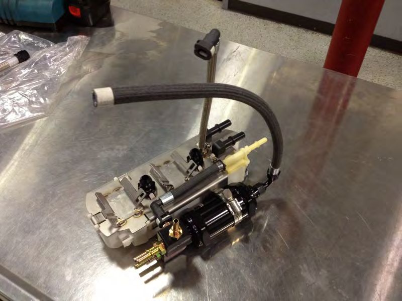
3. Disconnect both fuel lines from the sending unit. This is done by pinching
the white clips and pulling the line back. The hose and fitting will pull off
but the white clips will stay on the sending unit. This may take a bit of
twisting and pulling. Have towels handy to clean up fuel that will most
likely come out of these connections.

4. You can now remove the fasteners holding the sending unit plate down
and remove the sending unit plate. Pull the upper portion of the sending unit
out; the hoses and wires are long enough that it can be put off to the side.
5. You can now begin the removal of the in-tank portion of the fuel sending
unit. There are three lines on the back of the sending unit that must be
disconnected; these lines use the same style connector as the lines on the top
portion of the sending unit. Then reach under the front center of the unit and
it can be unclipped, slide forward to release it and then remove from the fuel
tank. If you find it easier to unclip it to slide it forward for easier access to
the lines you can remove the lines after.
6. Now that the sending unit is completely out of the gas tank you can begin
the disassembly. Begin by cutting off both hoses that go to the upper sending
unit and the single hose that goes to the return fitting on the lower portion of
the sending unit. Be very careful cutting hoses off of their fittings, you don’t
want to cut into the plastic under the hose. The best way to do this is cut off
the hose about ¼” from where the plastic barb ends inside the hose and then
cut parallel with the hose, this will make the hose begin to split so you can
see the plastic barb as you are cutting. Refer to the pictures below.
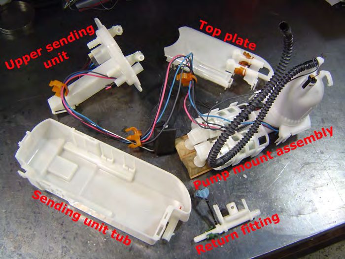
Next you can separate the top plate and the sending unit tub. This is done by
releasing numerous clips that are around it. To release the clips you gently
pull up the center plastic tab and then pinch the other two tabs together to
release the clip. Also remove the return fitting and pump mount assembly.
Don’t forget to unclip the fuel temp sensor from the tub and note its
orientation. This will be getting re-installed later on.
Once everything is apart you should end up with this:

7. You can now disconnect the wiring harness from the pump mount
assembly. You will not be using the original connectors so you can just cut
them off 10 inches before the fuel pump connector. In the harness for the
fuel pump that has a red wire there is an additional small black wire, when
you cut off the harnesses you can just leave the wire with the pump mount
assembly. Keep each ground wire with their power wire, tape them or zip tie
them together in the meantime before you connect them to the fuel pumps.

8. Now it is time to prepare the harness for the new pumps. Install the two
larger ring terminals onto the positive wires (red and blue) and the smaller
ring terminals onto the two ground wires (black).
At this point you are now done with the pump mount assembly and the top
plate, you can put them aside.

9. Next, install the pre-assembled AMS fuel pump mount top plate assembly
onto the factory sending unit tub; it snaps into place very tightly and pliers
may be needed to fully engage the clips.
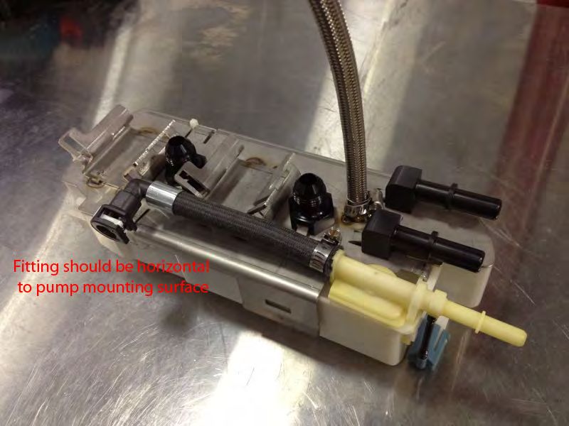
10. Install the short hose assembly onto the return fitting as show below. The
fitting should face to the side and be horizontal. It’s easier to install it onto
the return fitting before clipping the return fitting into the pump mount
assembly. The worm screw should face straight up.

11. Install the return fitting, it will also clip into place. If the clips from the
in-tank hoses are still on the fittings at this point remove them and put them
back on the lines.
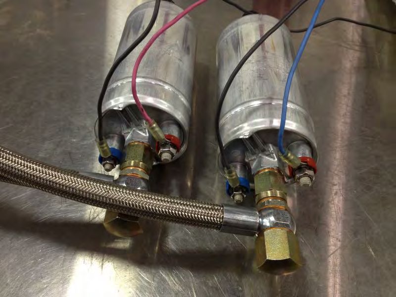
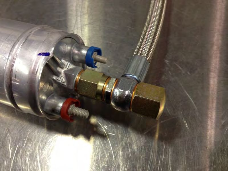
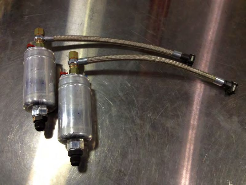
12. Next you will be preparing the fuel pumps for installation, find the two
lines that have banjo fittings on one end and quick connect fittings on the
other, these are the fuel pump outlet lines. Install the lines on the outlet of
the fuel pumps using the supplied nuts and washers. Clock as shown below,
making sure that the white clip on the fitting is facing up.
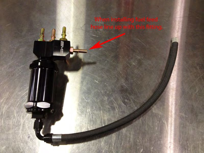
13. Next install the -8 AN fittings into the inlets of the fuel pumps using the
supplied crush washers.

14. Connect the fuel feed line to the fuel filter, line it up with the fitting as
pictured below.
Now the in-tank installation begins.
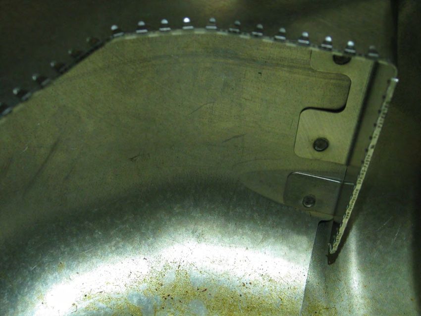
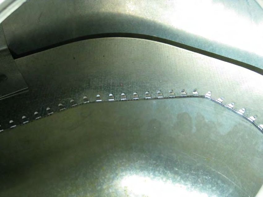
The Nissan GT-R fuel tank is baffled to try and keep fuel around the fuel
pump assembly during accelerating, braking, and hard cornering. These
baffles have sharp edges which may cut into the fuel-safe lines included with
the AMS GT-R Alpha Fuel System.
As an extra precautionary measure there are 2 sections of grommet edging
included that need to be installed BEFORE the installation of your AMS
GT-R Alpha Fuel System. The short section installs vertically while the
long section installs horizontally as shown below along the yellow lines (the
letters “A” and “B” are to be used as a continuation reference since the
entire baffle system could not be shown with just one picture).
AA
B
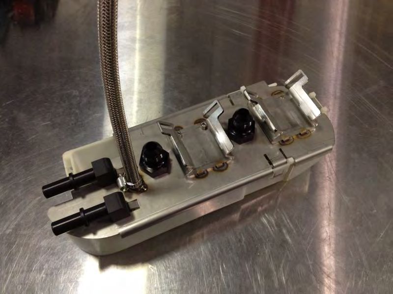
BAt this point you can place the pump mount assembly into the fuel tank
where it will be final assembled. The following pictures show it outside
of the tank for a better view.
15. Once in the tank you will first be connecting the lines that are in the tank
to the rear of the sending unit. The two large lines can go on either port, it
doesn’t matter. Dip the lines into fuel for lubrication and snap them onto the
ports on the sending unit.16. Next you will be installing the fuel filter and distribution block assembly. Thread the hose clamp through the tab on the side of the fuel pump mounting bracket. Then place the fuel filter in the clamp and clip the side fitting into the hose that you installed onto the fuel return fitting earlier and tighten the clamp. 17. Now it is time to install the fuel pumps. Begin by connecting their power wires as shown below using the supplied SS nuts and star washers. It doesn’t matter which pump gets what set of wires but as mentioned before you must keep the grounds with their respective power wires.
18. Begin by installing the pickup hose for the rear pump.
19. Next slide the clamp for the rear pump in place and lay the pump in the
mount with the ridge in the slot on the driver’s side of the mount. Tighten
the clamp just enough to locate the pump, don’t final tighten it yet. The
pump should be positioned so the electrical connections are horizontal. After
the pump is located properly connect the pickup hose to the bottom of the
pump. After that, clip the line coming from the top plate to the top port of
the distribution block.

20. Install the front pump in the same fashion.
21. Now would be a good time to clip in the fuel temp sensor. Note how it is
installed, it is offset. At this time you can also slide the whole assembly back
into the channels in the fuel tank until it clicks in place and doesn’t move.

22. Snap the fuel pump outlet lines to the two bottom ports of the
distribution block. Once both lines are connected take a look around and
make sure the lines aren’t rubbing on any sharp edges inside the tank, if they
are you can pivot the fuel pumps as needed to move the lines. Finally,
tighten the pump clamps.
23. At this point you can clip the return line onto the last port of the
distribution block, this should be the top horizontal fitting. This should be
the last hose you have, it will have a straight quick connect fitting on one
side and nothing on the other.
24. Now you will have two hoses left to connect, go ahead and pull them out
of the fuel tank in preparation of connecting them to the top sending unit
plate. You can also use the supplied zip ties and organize the wiring as you
see fit. The main idea here is to keep it as short as possible and near the back
of the tank away from the level sensing arm.
25. You can now connect the last two lines to the sending unit plate but first
the feed and return need to be determined. Looking at the lines that connect
to the top of the sending unit on the outside, the straight fitting is the feed
line and the 90° fitting is the return.

Connect the line coming from the fuel filter to the feed port and the line
from the distribution block to the return port. Clamp with the supplied hose
clamps.
26. Re-install the sending unit carefully. Watch it for as long as possible and
make sure that no hoses get caught or rub against the level sensing arm. Be
sure to place the blue o-ring in place, and tighten down the black ring. Re-
connect the feed and return lines. At this point you can now re-wire the fuel
pumps following the instructions next.
At this point you can now install our fuel pump rewire and hobbs switch
kit. This will supply full battery voltage to the fuel pumps for maximum
                                    flow.

Packing List:
  • 2 Relays w/ Harnesses
  • 4 Blue Ring Terminals
  • 8 14G-16G Butt Connectors
  • 4 18G-22G Butt Connectors
  • 20’ 14G Wire
  • 2 Fuse Holders w/ 30A fuses
  • 6” 1/8 Heat Shrink
  • 12” 3/16” Heat Shrink
  • Hobbs switch w/ install parts

Installation Instruction:

    1) Disconnect the negative battery cable. Install both fuse holders at
       the battery connecting them to the positive battery harness with a
       ring terminal. Connect a wire to each fuse holder using a butt
       connector. Run wires from each fuse holder back to the fuel pump
       area. This area is under the rear right seat cushion. I ran the wires
       into the car through a small slit I made in the factory engine wire
       harness grommet. This grommet is on the firewall behind the
       battery. I removed the sill plates and routed the wires back under
       the carpet. The wires from the battery get attached to wire 30 of
       each relay harness using a butt connector. The relay harness wire
       numbers are labeled on the bottom of the relay.
2) At this point you can now install the Hobbs switch that is used to turn on the 2nd fuel pump when 10 psi of boost is reached. Begin by running a boost source line into the cabin through the harness grommet in the same fashion as the power wires, this line must come from the intake manifold. IF you have a boost gauge in the car you can tap into that line instead of running a new one.
3) Connect this line to the Hobbs switch and mount the switch near the
   ECU. Next find pin 126 of the Grey colored ECU connector; this is
   the connector farthest back when referencing the front of the car.
   This wire will be blue. Tap one side of the Hobbs harness into this
   wire using the vampire clip and spade connector. The other Hobbs
   harness wire goes to a good ground point.
4) Remove the access cover and unplug both electrical connectors at
   the sending unit. Wire up one relay at a time.

    a. Cut the 2 pin connector off the factory harness leaving 1” of
       wiring on the connector side. Connect wire 87 of the relay
       harness to the orange wire of the connector using a butt
       connector. All relay wires should be routed through the
       grommet in the access panel to prevent wires from getting
       pinched or chaffed. Make wire connections using provided butt
       connectors. Extend the black wire of the connector long
       enough to reach a suitable ground. Connect it to ground using a
       ring terminal. Plug the 2 pin connector back into the sending
       unit. Connect the orange wire of the harness to wire 85 of the
       relay harness. Connect the black wire of the harness to wire 86
       of the relay harness.

    b. Cut the two thicker wires of the 5 pin connector leaving 1” of
       wiring on the connector side. Connect wire 87 of the relay
       harness to the brown wire of the connector. Extend the green
       wire of the connector long enough to reach a suitable ground
       location. Connect it to ground using a ring terminal. Plug the 5
       pin connector back into the sending unit. Connect the brown
       wire of the harness to wire 85 of the relay. Connect the green
       wire of the harness to wire 86 of the relay.
5) Reinstall the access panel making sure not to pinch any wires. Secure the relays off to the side and route the wiring so it will not get pinched by the seat cushion. Reinstall the seat cushion and put the interior back together. Install the fuses in the fuse holder and test fuel system operation.
You can also read