ÜNO/DÜO V2 Installation Instructions English - Interactive Playground
←
→
Page content transcription
If your browser does not render page correctly, please read the page content below
ÜNO/DÜO V2 Installation Instructions English Revision March 2021
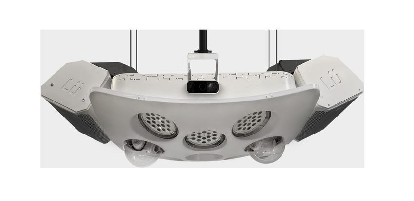
Table of contents

About this guide                                        Page 2

Lü Installation Installers Policies                     Page 3

Package Contents                                        Page 4

Not included items                                      Page 5

Technical specifications (Camera & projector module)    Page 6

Technical specifications (light & sound module)         Page 7

Technical specifications (Heart module)                 Page 8

Installation configuration (UNÖ & DUÖ)                  Page 9

Installation configuration (Side view)                 Page 10

ÜNO - Connection’s diagram (Top view)                  Page 11

DÜO - Connection’s diagram (Top view)                  Page 12

Installation configuration - Step by step (A to C)     Page 13

Installation rigging (Lighting Module - GYM D)         Page 14

Installation rigging (Lighting module - Palestra D)    Page 15
Installation rigging (Camera module E)                 Page 16

Installation rigging (Projection module F)             Page 17

Installation rigging (Heart module G)                  Page 18

Installation rigging (Cables H))                       Page 19

Installation – Projector Alignment I                   Page 20

Installation – System Statup J                         Page 21

Installation – Camera Calibration K                    Page 22

Installation – Camera Calibration L                    Page 23

Installation – Light & sound M & N                     Page 24

Acceptation of installation O                          Page 25

Complete Components Documentation                      Page 26
About this guide                                                Disclaimer
The Lü interactive system installation manual              The information and specifications contained in this
provides basic product information such as safety          installation manual are
and operation.                                             subject to change without notice.

Important safety Instruction
01 Do not use this system near water.

02 Clean only with a dry cloth.

03 Do not block any ventilation openings.

04 If mounting the product overhead, make sure there is adequate support for the product’s weight and always
      secure the product to the structure using a safety cable. Install the product following best practices and in
      accordance with local laws and regulations.

05 Only use accessories specified by the manufacturer.

06 Only plug this system after installation is completed and proper verification.

07 Always connect the product to a grounded circuit.

08 Do not use the Lü system in an environment where temperatures exceed +40 °C (104 °F).

09 Refer all servicing to qualified service personnel. Servicing is required when the system has been damaged
      in any way, such as power-supply cord or plug is damaged, liquid has been spilled, objects have fallen
      into the system, the system has been exposed to rain or moisture, does not operate normally, or has been
      dropped.

10 To completely disconnect AC power from the system, shut down the computer properly, the power supply
      cord must be unplugged from the ceiling and the circuit breaker on-off position.

11 Lü loudspeakers are easily capable of generating sound pressure levels sufficient to cause permanent
      hearing damage to anyone within normal coverage distance. Caution should be taken to avoid prolonged
      exposure to sound pressure levels exceeding 90 dB.

      IMPORTANT : Do not modify this product! Changes or modifications not expressly approved by the
      manufacturer could void the user’s warranty.

                                                                                                              Page 2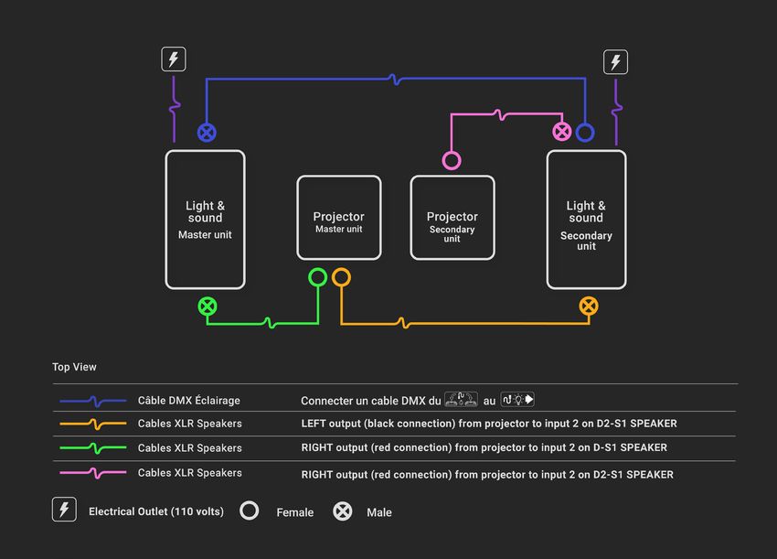
Lü Installation Installers Policies

Responsibility

Lü Interactive Playground Inc. is committed to provide a product that has been fully tested and was fully functional
at the time it was inspected in its Canadian warehouses.

It is the buyer’s responsibility to validate the condition of the product upon receiving it.

The installer assumes all liability resulting from accidents or damage to the product that occurred during the
installation process. In particular, they will be responsible for the repair and shipping costs for the spare parts.

The methods used, the procedures followed and the safety measures put in place during the installation
engage the responsibility of the installer, and this, for the total lifetime of the product.

For any further questions, information or validations, please contact our facility coordination
team at info@play-lu.com.

                                                                                                                  Page 3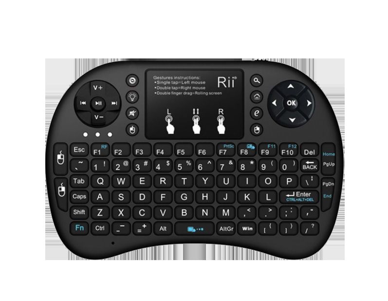
Package Contents
Each ÜNO/DÜO configuration consist of:
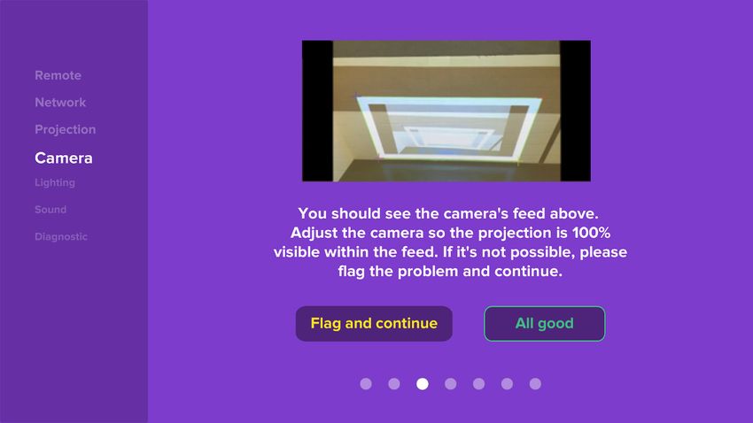
Heart module Light & sound module Projection module
Lü management system. 6 200 watts LED spotlights 6000 lumens WXGA* projector
to manage the ambient protected in a custom
lighting and general colors, 2 enclosure.
motorized LED light fixtures
for special light effects and 1 *WUXGA in Europe
powerful 2000 watts sound
system.
Camera module Stabilization cables system 1 projector’s remote controller
3D camera system.
1 Lü system remote 1 remote protection case Headset Microphone
controlle Xvive U3
Page 4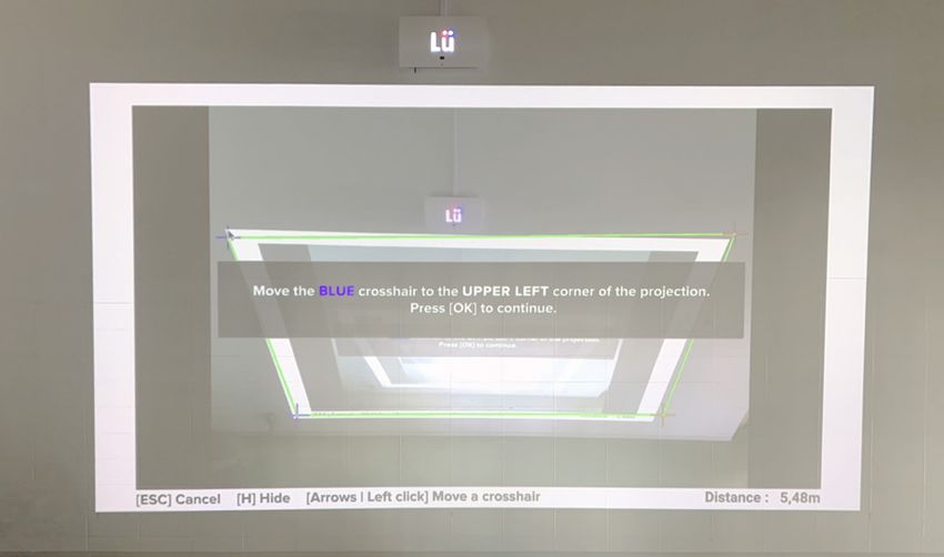
What is not in the box but required for the installation
The following items are not included in the box

01 All the material needed for structural hanging on the ceiling depending of construction type (ex. Cantruss,
      1/2” [13 mm] threaded rod, bolts and nuts, etc.).

02 Security steel cables and fasteners to secure components directly to building structure, second safety,
      3/16” (5 mm) cable for the main unit and 3/32” (2.5 mm) cable for the projector (length to be determined by
      the installer).

03 Self-drilling #8 2/3” (19 mm) metal screws (3 minimum).•

04 Lift system for persons (ex. scissor lift or scaffolding).

05 Tools (cable cutter, hex key [5 and 6 mm], wrench [7/16” and 3/4” at minimum], portable band saw and
      small angle grinder with metal cutting wheel).

06 DN 40 (1 1/2”-11.5 NPS) threaded pipe for hooking the projector module (length to be determined by the
      height of ceiling; the bottom part of the projector should be at 20’ [6 m] from ground).

07 DN 40 (1 1/2”-11.5 NPS) threaded pipe for hooking the camera module (length to be determined by the
      height of ceiling; the bottom part of camera should be at 18’ [5.5 m] from ground).•

08 2 celling plates (6 x 6” [150 x 150 mm]) or 8 x 8” [200 x 200 mm]) for receiving the projector and camera
      threaded pipes.

09 1 12’ (3 m) RJ45 network cable.

10 For the DÜO unit, 1 +50’ (15 m) XLR cable and 1 DMX cable (male-to-female) to connect the two units
      together.

11 Pump to inflate balls.

                                                                                                          Page 5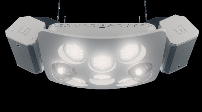
Technical specifications
ÜNO configuration

                                              Camera module                       Projector module

  Installation position*                15 pi from the wall / 18 high         28 pi from the wall / 20 pi high

  Size (L x W x H)                      6” x 4” x 5”                          22” x 20” x 16”

  Weight                                3.05 lb (1.38 kg)                     37 lb (16.78 kg)

  Rigging                               1.5” pipe mounting bracket            1.5” pipe mounting bracket
                                        or screw on the ceiling

  Power consumption                     110-240V - 36W (0.3Amp)               110-240V - 470W

      IMPORTANT : The installation parameters in this guide are optimal recommendations. These may change
      or vary depending on the installation context or space. Contact us for more information on the matter.

                                                                                                         Page 6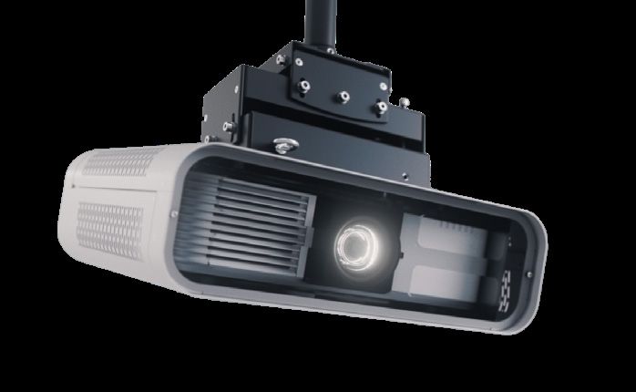
Technical specifications
Light and sound module

                                               With speaker                         Without speaker

  Installation position*                16’ from the wall / 20’ high          16 pi du mur

  Size (L x W x H)                      37” x 76” x 15”                       37’’ x 46” x 15’’

  Weight                                178 lb (80.74 kg)                     99 lb (44.91 kg)

  Rigging                               4 hanging points                      Screw on the ceiling

  Power consumption                     110-240V - 1106 W (9.21A)             110-240V - 674 W (5.62A)

      IMPORTANT : The installation parameters in this guide are optimal recommendations. These may change
      or vary depending on the installation context or space. Contact us for more information on the matter.

                                                                                                         Page 7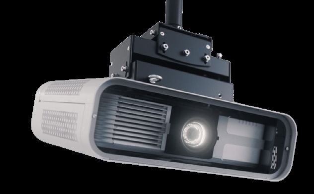
Technical specifications
Heart module

                                             Heart module

  Installation position*               12 inches over the projection (centered)

  Size (L x W x H)                     14” x 23” x 5”

  Weight                               18 lb (8.16 kg)

  Rigging                              Screw on the wall

  Power consumption                    110-240V - 216W (1.8A)

     IMPORTANT : The installation parameters in this guide are optimal recommendations. These may change
     or vary depending on the installation context or space. Contact us for more information on the matter.

                                                                                                      Page 8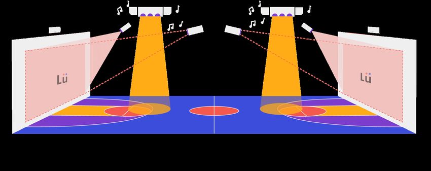
Installation configuration
ÜNO & DÜO

Lü can be sold in two different configurations. The ÜNO configuration broadcasts on an interactive wall while the
DÜO configuration includes two ÜNO units projecting on two interactive walls face to face or side by side. All it
takes is a few minor tweaks and additional connections to allow for a synchronized experience occupying the
entire gym.

                                                A         B C                  D

  ÜNO

                      A              B    C         D       D         C    B              A

  DUÖ

A Heart module
B Camera module
C Light and sound module
D Projector module

                                                                                                            Page 9
Installation configuration
Side view
All units must be mounted to the ceiling and aligned according to the projection surface. The diagram below
shows the optimal position. Some exceptions for special environments can be made, within the flexibility margins
(maximum tolerance).
Optimal position Max projection surface
Flexibility margin 19’ (5.8 m) wide
(maximun tolerance) 10’ 7” (3.3m) high
Page 10ÜNO - connection’s diagram
Top view
Connect modules 1, 2, 3 and 4 using this diagram
01
06
01
03
01 04
05
02
01 Cable 110 volt s 10 pieds (10 m )
02 HDMI Cable 65 pieds (20 m ) Electrical Outlet (110 volts)
03 Cables XLR Speaker s 25 pieds (7.5 m)
04 Cables USB Camer a 30 pieds (10 m ) Network Outlet
05 Cable DMX Ligh t 25 pieds (7.5 m)
06 Network Cables (not pr ovided ) 10 pieds (10m)
Page 11DÜO - connection’s diagram
Top view
01 Connect modules 1, 2, 3 and 4 using the ÜNO connection’s diagram
02 Inter-connect the two light modules together using this diagram
01
04
03 02
01
02
03
04
Male Female
IMPORTANT : The two computers must be connected on the same network for the DÜO system to work.
Only one DÜO system per network.
Page 12Installation configuration
Step by step (A to C)
A. Choose the best projection location on the wall (center and 4 corners)
The recommended width is 19’ (5.8 m) and the recommended height is 10.7’ (3.3 m). For the ideal position, the
lower end of the screen should be placed at 12” (20 cm) from the floor.Minimal height is 8” (20 cm) from the floor
and maximal height is 16” (40 cm) from the floor.
B. Mark the 4 corners of the surface of your projection screen on the wall and the position of the Heart, which
is to be centered 8 to 12” higher than the projection
Make sure to always to always have a 16:9 ratio for the screen..
C. Determine the position of the various modules on the ceiling by measuring the distances from the
projection wall and install the structural suspension elements
Ideally, all modules should be centered in front of the projection wall
Heart module
Install between 8” (20 cm) and 12” (30 cm) above the projection surface centered.
Light & sound module
Install at 20’ (6 m) from the floor and at 16’ (4.9 m) from the wall.Flexibility margin
(maximum tolerance): 12’ (3.65 m) to 26’ (8 m) from the floor and 16’ (4.9 m) to 18’
(5.5 m) from the wall. The module can be offset by ±1’ (30 cm).
Projection module
Install at 20’ (6 m) from the floor and at 28’ (8.5 m) from the wallFlexibility margin
(maximum tolerance): 28’ (8.5 m) to 40’ (12.2 m) from the wall (if installed at
recommended height). The module can be offset by ±3’ (1 m).
Camera module
Install at 18’ (5.5 m) from the floor and at 16’ (4.9 m) from the wall.Flexibility margin
(maximum tolerance): 12’ (3.65 m) to 18’ (5,5 m) from the floor and 15’ (4.6 m) to 16’
(4.9 m) from the wall. Maximum distance between the camera and the farthest corner
of projection should not exceed 23’ (7 m). The module can be offset ±3’ (1 m).
Page 13Installation rigging
Lighting Module - GYM (D)
D. Lift and install the lighting module in place, as follows:
01 Make sure the base is installed in the direction indicated by the sticker.
02 Hang the mounting base with the threaded rods, making sure the bolts are doubled.
03 Disconnect and then unscrew the two moving lights from the lighting tray with an 8 mm socket (so that the
weight of the module is under 23 kg [50 lbs] for a safe single-person installation).
04 Insert the light tray inside the mounting base on side 1 (green) first and push on side 2 (red)
until it locks into place.
05 Screw the light tray to the mounting base with the 8 bolts provided with a 13 mm socket.
06 Screw the moving lights inside the lighting tray and reconnect their respective cables so that they are working.
07 Screw the speaker brackets to each side of the mounting base using 8 bolts per bracket and a 13 mm socket.
08 Screw for the safety eyelets in the center of the speaker brackets and install the safety cables from the eyelets
to the building structure.
09 Install the speakers on the brackets by sliding the nuts through the eyelets downwards. Then tighten the nuts
with a 13 mm socket.
10 Attach speaker safety carabiners to the safety eyelets.•
11 Pass the 48” (122 cm) IEC cables through the mounting base, one on each side, and connect them to the
speakers.
* Safety cable
minimum requirements:
840 lbs (380 kg),
size 3/16” (5 mm)
(length to be determined)
A Make sure the mounting
base is installed in the
direction indicated by the
sticker
A
Page 14Installation rigging
Lighting module - Palestra (D)
D. Lift and install the lighting module in place, as follows:
01 Make sure the base is installed in the direction indicated by the sticker.
02 Hang the mounting base with the threaded rods, making sure the bolts are doubled.
03 Screw the mounting base directly to the ceiling using 8 screws appropriate for the structure.
04 Disconnect and then unscrew the two moving lights from the lighting tray with an 8 mm socket
(so that the weight of the module is under 23 kg [50 lbs] for a safe single-person installation).
05 Insert the light tray inside the mounting base on side 1 (green) first and push on side 2 (red) until it locks into
place.
06 Screw the light tray to the mounting base with the 8 bolts provided with a 13 mm socket.
07 Screw the moving lights inside the lighting tray and reconnect their respective cables so that they are working.
08 Unscrew the 6 nuts on each of the projector brackets and tilt the bottom bracket 90 degrees and put back the
bolts and nuts, so the bracket orientation can be adjusted.
09 Install the speaker brackets on either side of the projection screen at least 8’ (2.4 m) from the ground or above
the projection screen on either side of the Heart module.
10 Install the speakers on the brackets by sliding the nuts through the eyelets downwards.
Then tighten the nuts with a 13 mm socket.
11 Set the angle of the brackets, and tighten the nuts.
12 Connect speakers to the power outlet with the 10’ (3 m) IEC cables.
* Safety cable
minimum requirements: A Make sure the mounting
base is installed in the
840 lbs (380 kg),
direction indicated by the
size 3/16” (5 mm)
sticker
(length to be determined)
Page 15Installation - Rigging
Camera module (E)
E. Lift and install the camera module
01 Secure the camera module using the ceiling plate and a DN 40 (1 1/2”-11.5 NPS) threaded pipe (length to be
determined by the ceiling height; the bottom of the camera should be at 18’ [5,5 m] from ground).
02 Use a self-drilling screw at the ceiling plate to block any pipe rotation.
03 Connect power cords (1 connector) into the light module power strip.
Stabilization cables systems (to be used on all pipes longer than 24” [60 cm])
01 Install the ring on the pipe at 1/3 of the length of the pipe from the camera.
02 Install all 3 metal cables at 120 degrees angle towards the structure in the ceiling.
03 Stretch firmly the 3 cables with the turnbuckles until the pipe is stabilized at 90 degrees from the ceiling in
all directions and firmly holds in place.
Note: The camera
rotation bracket will
be locked later during
calibration.
A Ceiling mount with a DN A A
40 (1 1/2”-11.5 NPS)
threaded pipe
Page 16Installation - Rigging
Projection module (F)
F. Lift and install the projector module
01 Secure the projector module using the ceiling plate and a DN 40 (1 1/2”-11.5 NPS) threaded pipe (length to be
determined by the ceiling height; the bottom of the camera should be at 20’ [6 m] from ground).
02 Use a self-drilling screw at the ceiling plate to block any pipe rotation.
03 Install a safety cable from the eye bolt located between the top of the projector module and the structure.
Stabilization cables systems (to be used on all pipes longer than 24” [60 cm])
01 Install the ring on the pipe at 1/3 of the length of the pipe from the camera.
02 Install all 3 metal cables at 120 degrees angle towards the structure in the ceiling.
03 Stretch solidly the 3 cables with the turnbuckles until the pipe is stabilized at 90 degrees from the ceiling
in all directions and firmly holds in place.
* Safety cable minimum
requirements: 125 lbs
(55 kg), size 3/32”
(2.5 mm) (length to be
determined)
Note: The projector
rotation bracket will be
blocked later during
the projector alignment
procedure.
A Ceiling mount using a
DN 40 (1 1/2”-11.5 NPS)
threaded pipe.
Page 17Installation - Rigging
Heart module (G)
G. Lift and install the Heart, as follows :
01 Install the mounting plate to the projection wall in the center of the markers made in step 2. The bottom of
the mounting plate should be between 6’ (15 cm) and 12’ (30 cm) above the projection.
02 Insert the Hearth module from top to bottom into the wall mount.
03 Open the Heart cover and secure the module using the two M5 bolts with a 3 mm hex screwdriver.
04 Install the wire cover from the center of the Heart to the ceiling.
05 Connect the IEC cable to the Heart power bar.
06 Connect the HMDI cable to the PC computer.
07 Connect the USB cable to the PC computer where the CAMERA logo is.
08 Connect the Cat5 network cable to the PC computer where the logo is.
09 Connect the DMX cable where the light-bulb logo is.
10 Gather the five cables and secure them inside the cable cover up to the ceiling.
11 Close the Heart cover.
.
Page 18Installation - Rigging
Cables (H)
H.
01 Connect the Cat5 network cable to the network jack.
02 Connect the power cable to the power outlet.
03 Bring the other three cables to the light module, attaching them to the structure.
04 Connect the USB extension cable to the camera USB cable.
05 Unscrew the module grommet Philips screw, insert the cables and connect the DMX cable to the connector
of the bulb with wire logo and tie the excess USB cable inside the module.
06 Unscrew the side module grommet Philips screw (towards the projector) and pass the HDMI cable through
the module.
07 Connect the 25’ (7.5 m) XLR cable to one of the speakers using the IN port and then pass the cable into the
module through the projector grommet.
08 Connect the 6’ (1.8 m) XLR wire to the speaker already connected using the OUT port and connect the other
end to the other speaker using the IN port, then secure the wire with plastic fasteners.
09 Connect the IEC cable to the power bar of the light module and then pass the cable through the projector
grommet.
10 Gather the four cables and them to the structure.
11 Reinstall the grommet plates with the Philips screws.
12 Before moving to the projector, install the sound and light module fascia, lift the fascia upright and insert the
rod into the hinge mechanism.
13 Close the fascia and secure it to the hinge mechanism (two M5 x 25 nuts using a 8 mm socket) and to
the four corners (M5 x 30 nuts using a 3 mm hex screwdriver) while lifting the corner with one hand.
14 Run the cables along the building structure up to the projector.
15 Connect the IEC Cable to the projector.
16 Connect the HDMI cable to the projector HDMI port 1.
17 Connect the XLR cable to the red connector in the projector housing.
Page 19Installation - Projector Alignment
(I)
« Let’s get started »
At this stage, all components should be powered and
connected as per the connection diagram (see pages 14 to
16) The video projector should show the computer screen on
HDMI 1 - LET’S GET STARTED. Before continuing, perform the
projector alignment procedure.
I. Projector Alignment Procedure
01 Using the projector lens adjustment function, lower the image to the maximum position (vertically)
02 Physically guide the projector module towards the wall at 90 degrees and block pipe rotation with
the 4 screws on the bracket.
03 Center the image inside the markers using the lens adjustment function (horizontally).
04 Lock the lens adjustment mechanism.
05 Adjust the zoom to cover all four corners with a 10” (20 cm) overrun.
06 This extra room will allow the user to reposition the projector over time without having
to physically access the projector.
07 Adjust the focus at the center of the image.
08 Use the inclination and rotation adjustments on the module only in last resort.
09 Firmly stabilize and secure all the adjustments of the angles settings of the projector module.
10 Map the projected image on your 4 markers using the quick digital image distortion function. To do so, use
the projector remote, press the “Geometry” button, select “Quick corner” and adjust the four corners of the
markers on the wall (19’ [5.8 m] wide by 10’ 7” [3.3 m] high).
02 10
Page 20Installation - System Startup
J. System startup
Now, using the remote control keyboard, click “Next” and follow the self-test and calibration procedure.
Network
01 Network system, will check your internet connection, “Excellent!”, if not, check your connection.
02 Lü update, your LÜ must be up to date, if it is not, perform the update.
03 If you are using a DÜO system, check whether the two DÜO modules are connected.
Projection
01 Projection check, will check whether the projector is set correctly.
02 Projection height, must be at least 4” (10 cm) from the ground, and at most 1’ (30 cm).
03 Projector ratio, check that the screen ratio (16:9) is the right one; the shape of the square and
circle should be perfect.
Page 21Installation - Camera Calibration
K. Camera
01 Camera check, will check whether the camera is set correctly
Camera stream
Adjust the camera so that the projections are 100%
visible inside the stream. Please note that the projection image is in a 4:3 ratio of the displayed image.
01 Position the camera towards the wall, using the camera adjustments on the module and rotating the pipe.
02 The field of view is visible in the video projection, the view must be centered.
03 Once in place, secure all adjustments firmly and block the pipe from rotating using a self-drilling metal
screw. When the camera is in its final position and secured, click on “All good”.
Page 22Installation - Camera Calibration
L. Camera: Calibration, perform camera calibration
01 Turn off the lights in the projection wall area (do not have complete darkness in the room).
02 Click the “CALIBRATE” button
03 While the system is calibrating, a calibration grid will appear and after a few seconds the message
“Calibration Successful” will be displayed.
04 If the automatic calibration fails, it’s because the environment is too dark and the floor creates a dazzling
effect for the camera.
05 Even if the automatic calibration is a successful, perform a manual calibration.
06 Using the keyboard, press “M” to switch in manual calibration mode, then “H” to hide instructions, then “I” to
show invalid red pixels. There should be no red pixels in the play screen feed of view.
07 With the arrow on the keyboard, move each cross on the corner as shown below.
08 Mode de test
Test Mode, perform a calibration test by throwing balls on the wall. The position detected should show
a green dot at the place where the ball hit’s the wall. Repeat this operation with at least 20 balls at
different positions on the wall to ensure detection quality all over the surface. To exit this mode, click
“ESC” twice then “OK” on the keyboard.
False positives check 07
Make sure you don’t get false
positives (obstacles on the
projection wall). “Great!” If not, the
wall obstacles have to be removed.
Blue Corner
Purple Corner
Red Corner
Yellow Corner
Page 23Installation – Light & sound
M. Lighting: Lighting check, will test the lighting system.
01 Directional projectors color check, check the six projectors and the colors white, red, green and blue.
02 Swiveling lights check, the two swiveling lights are white and they make a circle motion..
Sound check : check if the audio system is working
01 The music should play.
System Diagnostic
“All good,” click on “Activate.” If there is a flagged item that you can’t fix, please contact Lü at
1-855-781-0797 to fix these issues before activation.
N. Check
01 Make sure that the video projection quality is good on the 4 corners, that the focus is perfect and that all the
projection system is well secured.
02 Make sure that the sound level is equal between the two speakers (it should be set to 0 dB on each of the
speakers).
03 Simulate a power shut down (clearly identify the proper electric breaker in case a restart is needed) and make
sure the system restarts properly and normally.
04 Validate that all pipe rotations are locked and all safety cables are in place.
05 Clean all components from dust or stains with a clean humid cloth.
Page 24O. Acceptation of installation
In compliance with the terms, conditions and provisions of the purchase and sale agreement (the “Agreement”)
between the undersigned (the “Buyer”) and Lü Interactive Playground Inc. (the “Company”), the Buyer, hereby:
a) certifies and warrants that the equipment (the “Equipment”) described in the above-referenced Agreement is
delivered, inspected, fully installed and operational as of the acceptance date (the “Acceptance Date”), as indicated
and defined below;
b) accepts all of the Equipment for all purposes under the Agreement and all related documents as of
this________________________ day of ___________________ 20 _________ (the Acceptance Date)
BUYER
NAME EMAILl
TITLE PHONE
Please provide the following photos of your installation :
01 Wide plan to see the entire system in the home menu.
02 A close-up of the hanging structure of each ceiling modules and safety cables.
03 A close-up of electrical and network connections.
Pictures of the 4 walls and ceilings of the place of the installation (gym) at the time of your departure, if a
04 system for occulting the windows is available, put it on the picture with the general lights on.
05 Signed acceptation of the installation.
Envoyez ces photos à : install@play-lu.com
Page 25Complete Components Documentation
For more detailed information about some selected Lü interactive playground components
Projector - Epson Powerlite L610w WXGA
https://epson.ca/Pour-le-travail/Projecteurs/Projecteurs-de-salle-de-r%C3%A9union/Projecteur-laser-
WXGA-3LCD-PowerLite-L610W/p/V11H904020
In North America: Projector - PowerLite L610W WXGA
In Europe: Projector - EPSON PowerLite L610U WUXGA
Loudspeakers - ELECTROVOICE ELX-10P
https://products.electrovoice.com/na/en/elx200-10p/
PC computer - Dell OptiPlex 3080 Micro
https://www.dell.com/en-ca/work/shop/dell-desktops-workstations/optiplex-3080-micro-desktop/spd/
optiplex-3080-micro
Wireless microphone - Microphone - Xvive U3 Receiver and Shure WH20XLR headset
https://www.xviveaudio.com/u3-p0071.html
https://www.shure.com/en-US/products/microphones/wh20
Contact informations
For support, any questions or comment on this product:
1-855-781-0797
support@play-lu.com
202-707, St-Vallier Street East
Quebec, QC, Canada
G1K 3P9
Page 26You can also read