North Star QRA Update - Chlorine and VCM plant (Rafnes) Report for: Wood - Direktoratet for samfunnssikkerhet og ...
←
→
Page content transcription
If your browser does not render page correctly, please read the page content below
Working together
                                       for a safer world

    North Star QRA Update
    Chlorine and VCM plant (Rafnes)

    Report for:
    Wood

Report no: PRJ11090011 Rev: Final
Date: 11 January 2019
Document history
 Revision       Date           Description/changes                Changes made by

 Draft          30.11.2018     First issue of report              Andrea Risan / Ingebjørg Valkvæ / Stian Jensen

 Final          11.01.2019     Comments from client               Andrea Risan / Ingebjørg Valkvæ
                               incorporated

Executive summary
Lloyds Register (LR) has been engaged by Wood and INOVYN Norge to conduct an update of the quantitative
risk assessment (QRA) of the Chlorine and VCM plant at the Rafnes Industrial Site (Grenland, Norway) to
accommodate any changes in the risk picture due to the North Star project. The North Star project includes
implementation of several modifications to the facility which will increase the total production capacity with
around 10 %.

The QRA update is conducted by using the existing risk model of the facility and adding the events potentially
caused by the planned modifications. A similar approach as applied in the existing QRA is applied in the risk
assessment of the North Star modifications. In that manner the risk level before and after the modification can
be compared. The risk acceptance criteria proposed by DSB are applied in the study. Hence, the focus in the
study is directed towards major accident events that may cause fatal exposure outside of the boundary of the
facility.

The main conclusion of the study is that the North Star project only contributes with a modest risk increase to
third parties, and that the main risk drivers remain unchanged after the update. It is still toxic releases of chlorine
and HCl that dominates the risk picture, in addition to BLEVE events in the VCM storage area. The calculated risk
picture is shown in the below figure.

Report no: PRJ11090011 Rev: Final                                                                                 Page ii
Date: 11 January 2019                                                                              ©Lloyd’s Register 2019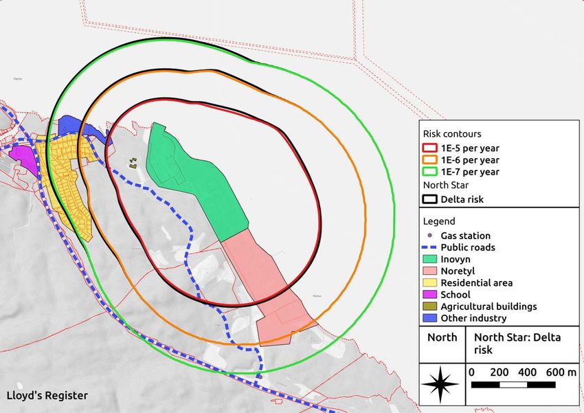
Glossary/abbreviations
ALARP                         As Low As Reasonably Practicable

AT                            The Norwegian Labour Inspection Authority (Arbeidstilsynet). A
                              governmental agency under the Ministry of Labour, focused on occupational
                              safety and health

BLEVE                         Boiling Liquid Expanding Vapour Explosion

CFD                           Computational Fluid Dynamics

DSB                           Norwegian Directorate for civil protection (Direktoratet for
                              Samfunnssikkerhet og Beredskap)

EDC                           Ethylene DiChloride, 1,2-dichloroethane

ESD                           Emergency Shut Down

EX                            Ex-equipment or explosive protected equipment, both electric and
                              mechanical.

FTM                           Forslag Til Modifikasjoner

Hazardous substances          Flammable, reactive, pressurised and explosive substances

HAZID                         Hazard Identification

Report no: PRJ11090011 Rev: Final                                                                               Page iii
Date: 11 January 2019                                                                            ©Lloyd’s Register 2019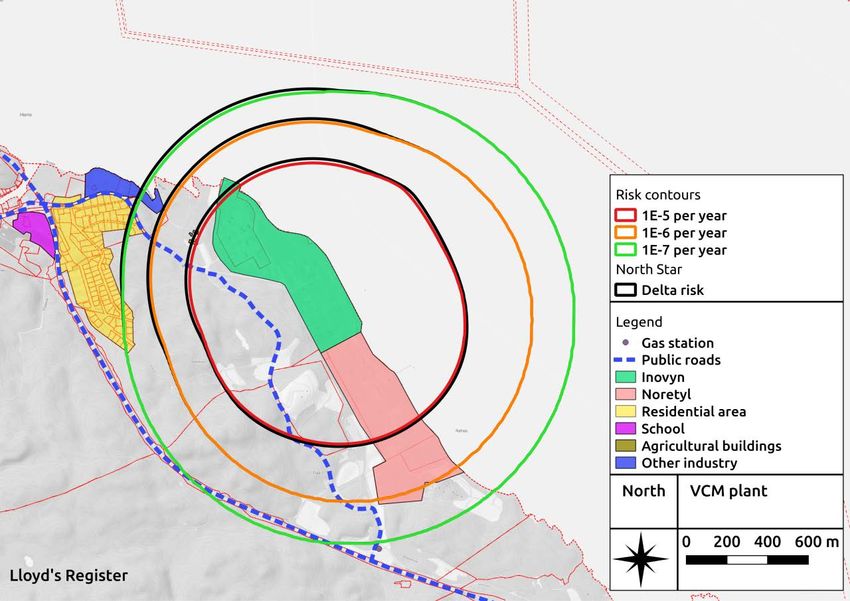
HCl                           Hydrogen Chloride

HTDC                          High Temperature Direct Chlorination

IR                            Individual Risk

LFL                           Lower Flammability Limit

LNF                           Landbruk-, Natur- og Friluftsområde

LOC                           Loss Of Containment

OHCL                          Oxy HydroChlorination

PSD                           Process Shut Down

QRA                           Quantitative Risk Analysis

RAC                           Risk Acceptance Criteria

Safeti                        Safeti QRA software tool - A user-friendly, industry standard method for
                              carrying out Quantitative Risk Assessments (QRA) of onshore process,
                              chemical and petrochemical facilities. Developed by DNV-GL.

Third party (3rd person)      People outside the production plant that may be affected by its activities.

                              (2nd person: People that are not directly related to the operation of the
                              plant, but benefit from being close to the plant

                              1st person: People who are directly involved in the operations of the plant,
                              i.e. the employees at the plant)

VCM                           Vinyl Chloride Monomer

Report no: PRJ11090011 Rev: Final                                                                                Page iv
Date: 11 January 2019                                                                             ©Lloyd’s Register 2019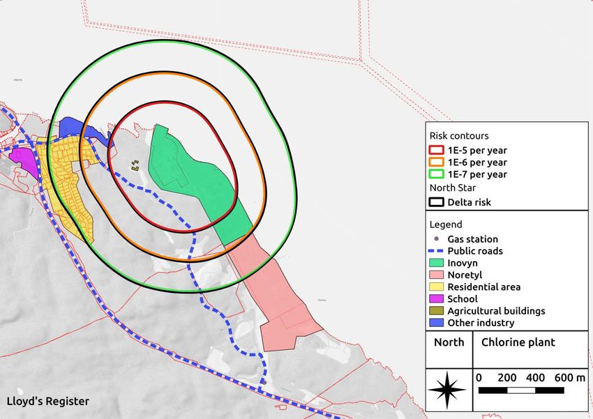
Table of contents                                                                 Page

1      Introduction                                                                     1
       1.1    Background                                                                1
       1.2    Objective                                                                 1
       1.3    Scope of work                                                             1
       1.4    Presumptions and limitations                                              1
              1.4.1       Presumptions                                                  1
              1.4.2       Limitations                                                   1
       1.5    Regulations and standards                                                 2
2      Framework                                                                        2
       2.1    Methodology                                                               2
       2.2    Assumptions and input data                                                4
       2.3    Acceptance criteria                                                       4
3      System description                                                               5
       3.1    General description                                                       5
       3.2    Process description                                                       5
              3.2.1       Chlorine – INOVYN scope                                       5
              3.2.2       VCM – Wood scope                                              6
       3.3    North Star project                                                        7
              3.3.1       VCM plant modifications                                       7
              3.3.2       Safety measures for the new HTDC module                       8
              3.3.3       Water curtain in the HTDC module                              8
              3.3.4       Chlorine plant modifications                                  9
       3.4    Safety measures                                                           9
              3.4.1       Pressure monitoring and shutdown                              9
              3.4.2       Chlorine absorption system                                    9
              3.4.3       Gas detection and emergency shutdown                          9
              3.4.4       Fire proofing of storage spheres                              9
              3.4.5       Emergency preparedness                                        9
4      Selection of hazardous events                                                    9
       4.1    Existing QRA                                                              9
       4.2    Scenarios for the new HTDC module                                       11
       4.3    Scenarios for the new OHCL reactor                                      12
       4.4    Risk screening of other North Star modifications                        12
5      Frequency analysis                                                             14
6      Consequence analysis                                                           15
       6.1    Event tree                                                              15
       6.2    Fatality criteria                                                       16
       6.3    Consequence modelling                                                   16
7      Risk picture and risk evaluation                                               18
       7.1    Total risk picture                                                      18

Report no: PRJ11090011 Rev: Final                                                  Page v
Date: 11 January 2019                                               ©Lloyd’s Register 2019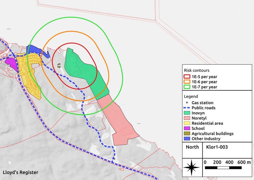
7.2    Risk from the chlorine plant                                19
       7.3    Risk from the VCM plant                                     21
       7.4    Individual risk at nearest resident                         24
8      Uncertainties                                                      26
9      Potential conservatism in the QRA                                  26
       9.1    Release durations and transient effects                     26
       9.2    Terrain effects                                             27
       9.3    Release modelling                                           27
       9.4    Event frequencies                                           27
       9.5    BLEVE                                                       27
       9.6    Flash fire envelope                                         27
10     Conclusion and recommendations                                     28
       10.1 Recommendations                                               28
       10.2 Conclusions                                                   28
11     References                                                         29

Appendix A – Assumptions and input data
Appendix B – Risk screening workshop – VCM plants
Appendix C – Risk screening workshop – Chlorine plant

Report no: PRJ11090011 Rev: Final                                      Page vi
Date: 11 January 2019                                   ©Lloyd’s Register 2019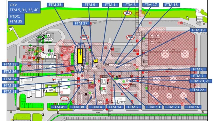
1        Introduction
1.1      Background
         Lloyd’s Register (LR) has been engaged by Wood and INOVYN Norge to carry out an update of the
         quantitative risk assessment (QRA) for INOVYN’ s Chlorine and Vinyl Chloride Monomer (VCM) plant at
         the Rafnes Industrial Site (Rafnes) conducted in 2015 (Ref. /1/).
         The North Star project introduces several modifications to the Chlorine and VCM plant in order to
         increase the production capacity of the plant. The modifications include:
         •    Installation of a new High Temperature Direct Chlorination (HTDC) module
         •    Replacing the existing Oxy HydroChlorination (OHCL) reactor with a new one
         •    Several other modifications to process vessels and equipment in the VCM plant to allow for the
              increased capacity
         •    Installation of a new electrolyser in the chlorine plant
         •    Replacement of the hydrogen compressor, chlorine compressor and chlorine cooler.
         INOVYN Norge is classified as a so called major accident facility according to “Storulykkeforskriften”
         (Ref. /9/). Hence, the facility is required by regulations to minimize the risk for major accidents. The QRA
         can be seen as part of the effort to reach this objective.

1.2      Objective
         The objective of the QRA update is to investigate the impact of the North Star project on the existing
         risk picture at INOVYN’s facility at Rafnes. The modifications will be assessed and included in the existing
         QRA of the facility. Potential risk drivers will be identified, and it will be evaluated if the project
         introduces significant change in the risk for third parties. The proposed risk acceptance criteria by DSB
         (Ref. /2/) are applied in the risk assessment.

1.3      Scope of work
         The scope of work involves using the risk model developed in the existing QRA of INOVYN’s facility at
         Rafnes as a starting point. The risk model is implemented using the Safeti software. Events introduced
         by the North Star project will be handled in a similar manner as in the existing QRA by using, e.g., the
         same event frequency references, fatality criteria and overall assumptions as a basis. The focus in the
         QRA is to address major accidental events that may influence the extent of risk zones (“hensynssoner”
         in Norwegian) around the facility.

1.4      Presumptions and limitations
1.4.1 Presumptions
         The following presumptions apply to the study:
         1. Normal operation including regular shut down and maintenance and start up activities are the base
            of the QRA.
         2. If risk reducing measures are disengaged during operation, it is a prerequisite that compensating
            measures are implemented so that the barrier’s function is kept. If compensating measures are not
            taken, the QRA is not valid.
1.4.2 Limitations
         The following limitations apply to the study:
         1.   Events while ship is at sea or mooring are not included
         2.   The ships on-board systems (tanks, pumps, piping) are not included

Report no: PRJ11090011 Rev: Final                                                                                Page 1
Date: 11 January 2019                                                                             ©Lloyd’s Register 2019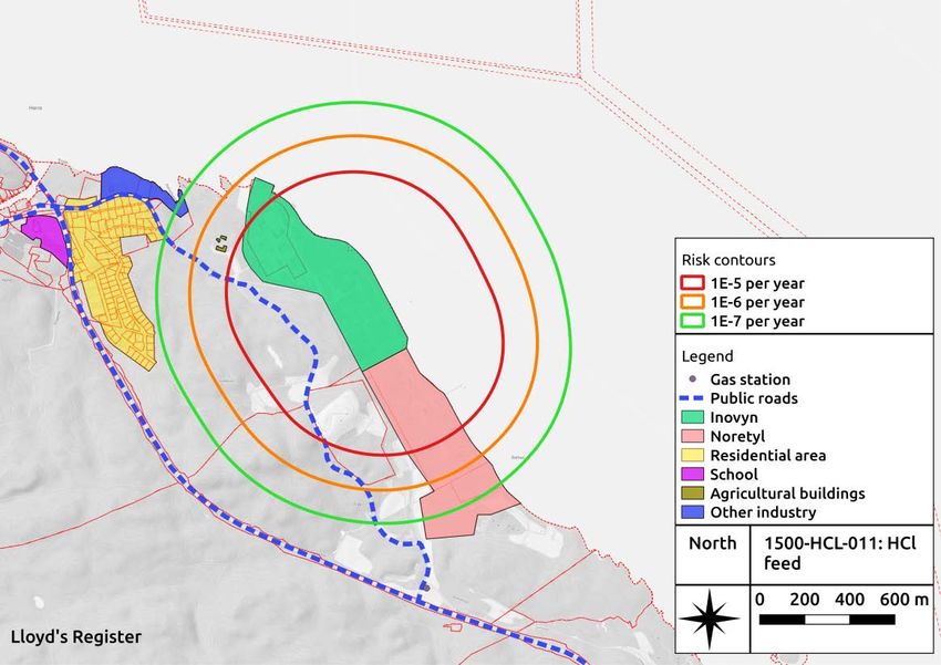
3.   The tunnel with export pipelines to Herøya is not included. A separate risk assessment for the
              tunnel has been conducted, Ref. /3/
         4.   Escalation effects have not been quantified. An escalation is defined as an initial event on the site,
              e.g. a fire that impairs other equipment containing flammable or toxic material on the same site.
              Thereby leading to a larger fire or more severe toxic effects. One exception is the inclusion of
              Boiling Liquid Expanding Vapour Explosion (BLEVE) events in the QRA. A BLEVE can be considered
              as an escalated event, since a prerequisite for such a scenario to occur is long exposure time to
              relatively high heat loads, i.e. fire exposure.
         5.   Domino effects, e.g. events where fire and explosion triggers new release scenarios (or other
              effects) from equipment in adjacent facilities, have not been calculated specifically. Domino effects
              are discussed in the risk analysis from 1991 and 1998 (Ref. /4/ and /5/) and in the report "Vurdering
              av dominoeffekter mellom fabrikkanleggene på Borealis AS, Noretyl AS og Hydro Polymers AS i
              forbindelse oppdatering av Sikkerhetsrapporten for Hydro Polymers og Noretyl", Ref. /6/.

1.5      Regulations and standards
         The most central regulations related to health, safety and the environment (HSE) for the onshore
         chemical process industry which come under the supervisory authority of the DSB and AT are found in
         the HSE regulations and the working environment regulations.
         The following relevant regulations apply for INOVYN Norge and set the premise for the current risk
         assessment:
         •    DSB: "Forskrift om håndtering av brannfarlig, reaksjonsfarlig og trykksatt stoff samt utstyr og
              anlegg som benyttes ved håndteringen (forskrift om håndtering av farlig stoff) ", FOR-2009-06-08-
              602, 8. juni 2009, Ref. /7/.
         •    DSB Temaveileder ”Sikkerheten rundt anlegg som håndterer brannfarlige, reaksjonsfarlige,
              trykksatte og eksplosjonsfarlige stoffer: Kriterier for akseptabel risiko”, May 2013, Ref. /8/.
         •    Storulykkeforskriften FOR-2005-06-17-672, Council Directive 96/82/EC of 9 December 1996 on the
              control of major-accident hazards involving dangerous substances, Ref. /9/.
         Also note, that since the QRA was established, DSB has introduced a new guideline for conducting
         QRAs, i.e. “Retningslinjer for kvantitative risikovurderinger for anlegg som håndterer farlig stoff” (Ref.
         /10/). Those new guidelines are not adopted at the present stage.

2        Framework
2.1      Methodology
         The overall methodology used in the QRA is illustrated in Figure 2.1.

Report no: PRJ11090011 Rev: Final                                                                                 Page 2
Date: 11 January 2019                                                                              ©Lloyd’s Register 2019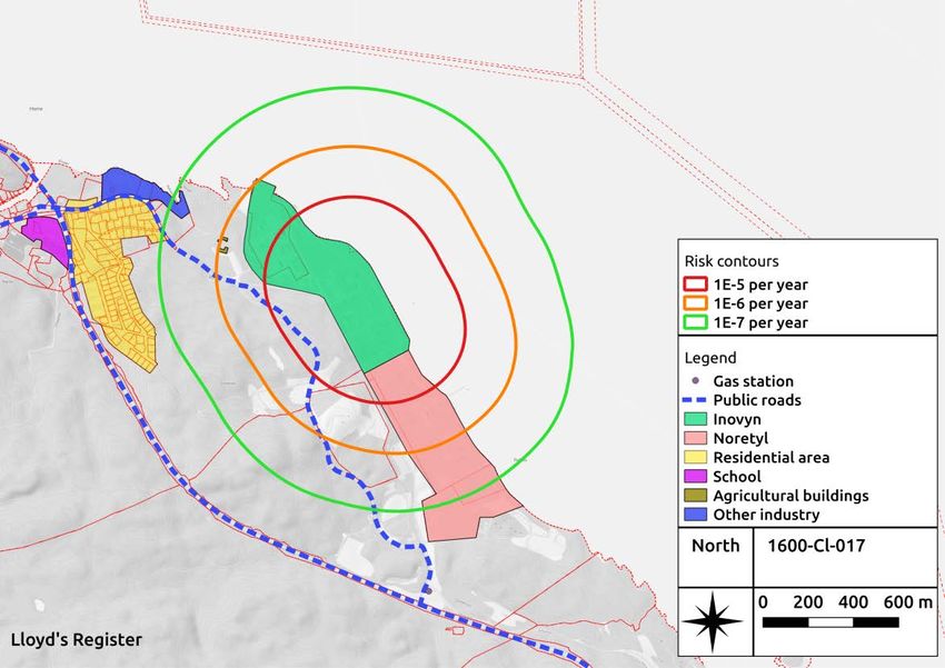
Figure 2.1 - QRA methodology

         The building blocks of the study are briefly discussed below.
         1.   Risk acceptance criteria
         The acceptance criteria are used to evaluate the risk and aid in decisions regarding need for risk
         reducing measures. The acceptance criteria applicable for this project are presented in Chapter 2.3.
         2.   System definition
         A presentation of the system included in the scope of the QRA and its limitations are presented in
         Chapter 3.
         3.   Hazard identification
         A hazard identification (HAZID) workshop was performed at Rafnes during the previous QRA update in
         2015 and was used to define relevant scenarios for the QRA.
         A risk screening workshop identifying the possible hazards related to the modifications of the North Star
         project was performed at Rafnes in October 2018. The results from the risk screening workshop are
         summarized in Chapter 4 and documented in Appendix B and C.
         4.   Frequency analysis
         The frequency analysis is performed to select and define a set of scenarios that represent the risk posed
         by the Chlorine and VCM plant. The frequency analysis is described in Chapter 5.
         5.   Consequence analysis
         The possible consequences from each scenario from the frequency analysis are simulated using the
         software Safeti. The consequence analysis is described in Chapter 6.
         6.   QRA results – Risk picture and risk evaluation
         The risk picture is the result of the frequency analysis and the consequence analysis. The resulting risk
         picture for the Chlorine and VCM plant is presented in Chapter 7. The risk is evaluated by comparing
         the resulting risk picture with the applied RAC.
         7.   Risk-reducing measures
         Risk-reducing measures are recommended in order to meet the acceptance criteria or to further reduce
         the risk in line with ALARP. Recommendations are given in Chapter 10.

Report no: PRJ11090011 Rev: Final                                                                                Page 3
Date: 11 January 2019                                                                             ©Lloyd’s Register 2019
2.2 Assumptions and input data
All assumptions made in the study are presented in the assumption sheets in Appendix A together with
any data used for the study including wind data, population data and vulnerabilities.
2.3 Acceptance criteria
This study applies the Risk Acceptance Criteria (RAC) proposed by Norwegian authority DSB (Ref. /8/) in
their guidance document regarding RAC for facilities storing and handling hazardous substances. The
RAC are based on the individual risk contours calculated for the facility, and defines a number of zones
for special consideration. The RAC are presented in Table 2-1 and Figure 2.2.
Table 2-1 - Acceptance criteria, defined zones for consideration
Zone for Acceptance criteria Provisions for the zone (accepted
consideration object and activities in the zone)
Inner zone IR is higher than 1E-5 per Primarily within the facility’s property
year limits, extension into LNF-areas may be
allowed.
Intermediate zone IR is in between 1E-5 and Public roads, railway, quays are accepted
1E-6 per year and also industries and offices.
No permanent housing is permitted,
though some scattered housing may be
permissible under certain circumstances
Outer zone IR is in between 1E-6 and Housing, public facilities, shops, smaller
1E-7 per year overnight accommodations and other
usage for the general public accepted
Outside outer zone IR is lower than 1E-7 per Schools, hospitals, shopping centres,
year hotels, large venues etc. should be
outside the outer zone
Figure 2.2 - Illustration of safety zones around a plant with marked iso-contours that defines
the zones (Ref. /8/)
Report no: PRJ11090011 Rev: Final Page 4
Date: 11 January 2019 ©Lloyd’s Register 20193 System description
3.1 General description
The INOVYN Norge production plant for vinyl chloride monomer, VCM, is located at Rafnes industry
facility in Bamble community in Norway. Figure 3.1 show an overview of the Rafnes industrial site and
the surrounding areas of the Chlorine and VCM plants. The closest residential area, Herre, is located
west of the chlorine plant. The closest house is approximately 400 m from the fence around the
chlorine plant. Highway 353 marks the property boundary towards west. The road is at a higher
elevation than the plant and there is also a ridge between the plant and the road. There is also a smaller
road that goes alongside the plant fence before it connects to the highway again. This road is public,
but can be blocked in case of an emergency.
Figure 3.1 – Overview of the Chlorine/VCM plant and the surrounding areas
Located southeast on the Rafnes industrial site and neighbouring the VCM plant is Noretyl AS ethylene
plant. A polyethylene plant owned by INOVYN Bamble AS lies further to the southeast, at the
Rønningen industrial site (not shown in Figure 3.1).
This report presents the risk introduced from the North Star project associated with the Chlorine and
VCM plant.
3.2 Process description
3.2.1 Chlorine – INOVYN scope
There are two almost identical production lines (Chlorine 1 and 2) with membrane electrolysers for
production of chlorine. Chlorine is produced on the anode side and hydrogen and caustic soda on
cathode side. The moist chlorine gas is cooled, filtered and dried with sulphuric acid before being
compressed to approx. 5.5 bar(g) and sent to the VCM plant. The chlorine gas from both line 1 and 2 is
delivered in a single 250 mm header.
Report no: PRJ11090011 Rev: Final Page 5
Date: 11 January 2019 ©Lloyd’s Register 2019The hydrogen gas is cooled, filtered, dried and compressed and sent to the VCM plant and to the
neighbouring industry Noretyl to be used as raw material or fuel gas.
The caustic soda is concentrated to 50 % using evaporation and then stored. The caustic soda is
exported by trucks and shipped by boats to several customers.
The chlorine plant is divided into the following areas:
• Water purification
• Brine
• Cell room
• Caustic soda
• Hydrogen
• Lean brine dechlorination
• Emergency scrubber/recovery chlorine
• Chlorine.
3.2.2 VCM – Wood scope
VCM is produced from the intermediate substance Ethylene DiChloride (EDC). EDC is produced in two
separate processes in the VCM plant. The first process is by direct chlorination, using ethylene gas from
Noretyl and chlorine gas from the chlorine plant. The second is by oxychlorination, using hydrogen
chloride, hydrogen gas, ethylene gas and air. The EDC from the direct chlorination and oxychlorination
is purified (distilled to remove light and heavy bi products) and intermediately stored before being sent
to the cracking furnaces.
VCM is produced by cracking EDC to VCM and Hydrogen Chloride (HCl) at a temperature of approx.
500 °C and 20 bar(g) pressure. The gas out of the cracking furnaces still holds a large amount of EDC
and a number of steps are needed to separate VCM, HCl and EDC from the raw gas. The EDC is
condensed by cooling and HCl stripped off by reducing the pressure. Finally a distillation process
removes the last traces of HCl and EDC and by-products from VCM. The pure VCM is stored as liquid in
pressurized spherical tanks before being offloaded by ship or pumped through piping under the
Frierfjord to INOVYN Norge PVC plant at Herøya.
Utility systems include steam and condensate system, cooling water system, waste water treatment,
incinerators for vented gases and fuel gas system.
The VCM plant is divided into process area, tank farm, control centre, flare and quay. Production, as
well as sewage treatment and combustion of bi-products, takes place in the process area. The process
area is further divided into a number of plant areas as listed below:
• 1100 - Oxychlorination
• 1200 - EDC-recovery
• 1300 - EDC purification
• 1400 - Cracking
• 1500 - VCM-purification
• 1600 - Direct chlorination
• 1700 - HCl-unit
• 1800-1900 - Waste water treatment
• 1800 - Incinerator
• 2700 - EDC/VCM/by-product storage
• 3000 - Jetty 2.
Report no: PRJ11090011 Rev: Final Page 6
Date: 11 January 2019 ©Lloyd’s Register 20193.3 North Star project
The North Star project introduces several modifications to increase the capacity of the Chlorine and
VCM plant. The modifications are designed to increase the overall production rate of the plant with
around 10 %.
3.3.1 VCM plant modifications
The main modifications to the VCM plant are installation of a new HTDC module and an OHCL reactor:
• The HTDC module is a new module at INOVYN and will operate in parallel to the existing LTDC
module. It is expected to have a footprint of approximately 28 m x 8 m with three levels. The
module is relatively congested with process equipment and reactors. A process flow diagram of the
new HTDC module located in the VCM plant is shown in Figure 3.2
• The OHCL reactor will replace an existing reactor. The flow throughput and the volume of the
reactor will be increased. The existing reactor will be put out of operation and work as a spare
reactor.
In addition, several minor modifications, or FTMs (“Forslag Til Modifikasjoner”), will be made to allow
for the increased production capacity. Details of the scope of these modifications can be found in
Appendix B. Figure 3-3 illustrates the locations of the North Star modifications in the VCM plant.
Figure 3.2 – Process flow diagram (PFD) of HTDC module
Report no: PRJ11090011 Rev: Final Page 7
Date: 11 January 2019 ©Lloyd’s Register 2019Figure 3-3 – VCM plant – Location of FTMs. The yellow box (left) is the location of the new
HTDC module, and the orange box (right) is the location of the OHCl reactor
3.3.2 Safety measures for the new HTDC module
The North Star modifications include installation of gas detection systems in the new HTDC module. The
following gas detection systems will be installed:
• EX detectors for explosive gas detection
• Chlorine gas detectors (point detectors)
• Sniffing detectors for detection of toxic gas releases (low concentrations).
Further, there will be replacement of the existing flame arrestor and fire water monitor for the HTDC
module. Fire water monitor X1032/12 shall be replaced by a new remotely controlled fire water monitor
(X1032/16). Fire water monitor X1032/10 will be moved to ensure better coverage of the HTDC area in
addition to the originally covered process areas.
3.3.3 Water curtain in the HTDC module
There is a discussion in the North Star project regarding the possible implementation of a water curtain
between the HTDC module and the vessels in area 1600. The main purpose of such a water curtain
would be to reduce the likelihood of escalation from an accidental event in the HTDC module to the
wash tanks in area 1600.
In general, water curtains are used to protect personnel from high heat radiation levels during, e.g.
escape or other special events such as an ignited flare during a blow down situation. For protection of
vessel containing hazardous substances, it is probably more optimal to apply a deluge system. Fire water
can then be applied over the tanks to enhance the cooling effect.
The HTDC module is already covered be two remotely controlled fire monitors. One of which has a
direct line of sight to the abovementioned vessels. This is likely to be sufficient. However, to further
quantify the benefit of a deluge system, in addition to fire monitor, one could establish:
• The consequence of vessel ruptures.
• The probability, or frequency, of fires that may lead to loss of containment of hazardous substances
in the 1600 area.
Report no: PRJ11090011 Rev: Final Page 8
Date: 11 January 2019 ©Lloyd’s Register 2019If INOVYN has a criteria for an unacceptable escalation this can be applied in the decision making, when
the consequence and likelihood of vessel rupture (escalation) has been established.
If the consequence of a vessel rupture is low, i.e., if it does not significantly increase the severity of the
event, a deluge system is unlikely to be in the ALARP range of measures. A similar argument can be
made if the frequency of fires that may cause an escalation is low.
The above discussion assumes that there is no BLEVE potential in area 1600. The matter should be
assessed in more detail if that is not the case.
3.3.4 Chlorine plant modifications
The modifications to the chlorine plant are:
• Installation of a new electrolyser
• Increased capacity of the chlorine compressor, hydrogen compressor and chlorine cooler.
Details of the scope of these modifications can be found in Appendix C.
3.4 Safety measures
3.4.1 Pressure monitoring and shutdown
The pressure is monitored in the chlorine header and many other places in the process. Detected very
low pressures, e.g. in case of a larger leak, lead to automatic shutdown.
3.4.2 Chlorine absorption system
In an event of leak or failure in the chlorine plant the production in the cells are stopped and the
emergency absorption system is started. The chlorine gas is absorbed in sodium chloride, producing
sodium hypochlorite. A low pressure is created with ejectors and the produced chlorine gas is sucked
through the absorption system.
3.4.3 Gas detection and emergency shutdown
Chlorine gas detectors are located both indoors in the chlorine plant and outdoors in the chlorine and
VCM plant. There is no automatic shutdown but an operator will directly suit up in gas protection gear
and look for the leak.
There is also VCM gas detectors located in the process area and around pumps in the storage area. The
detectors are very sensitive and detect at ppm level. No automatic shutdown and procedures are the
same as for chlorine.
3.4.4 Fire proofing of storage spheres
The VCM storage spheres are fitted with fire detection and deluge in order to minimize risk of
escalation and possible BLEVE event in the storage area.
3.4.5 Emergency preparedness
At Rafnes and Rønningen there is a common emergency preparedness plan and organisation. Norward
is a company providing services within industrial emergency preparedness and they are localized in the
fire station at Rafnes. They provide their services to the plants on Rafnes and Rønningen.
4 Selection of hazardous events
This section selects the units or process segments that may cause hazardous events that can influence
the risk picture around the facility.
4.1 Existing QRA
The events included in the present study are based on evaluations made in the previous QRA update in
2015, Ref. /1/. The general assumptions regarding each subsystem are presented in Table 4.1.
Report no: PRJ11090011 Rev: Final Page 9
Date: 11 January 2019 ©Lloyd’s Register 2019Table 4.1 – General assumptions regarding scenario selection, ref. /1/
Part of plant Scenarios included in General assumption
the QRA
Chlorine plant
Water purification No scenarios No (or limited) hazardous substances
Brine No scenarios No (or limited) hazardous substances
Cell room Cl2 header in the cell Leaks from individual cells and anolyte/
room is considered catolyte solutions are not considered to pose
a threat outside the cell room
Leak of H2 is assumed to give fire in the cell
room with only local effects. Domino effects
towards Cl2 system is considered negligible
Caustic soda No scenarios Leaks of NaOH solution is assumed to give
only local effects
Hydrogen H2 header to VCM is Leaks of H2 from compressors etc. are
considered assumed to give only local effects.
Domino effects towards Cl2 system is
considered negligible
Lean brine No scenarios Small amounts of Cl2, low pressures vacuum-
dechlorination 0.2 bar(g) and leaks are assumed to give only
local effects.
Leaks of anolyte solution is assumed to give
only local effects
Emergency If pumps P3704, P3706 Pumps are connected to emergency power.
scrubber/recovery stops while production Small amounts of Cl2, low pressures vacuum-
chlorine trips 0.2 bar(g) and leaks are assumed to give only
local effects
Chlorine All leak points of Cl2 Leak of H2SO4 is assumed to give only local
gas are considered effects.
No liquid Cl2 at any point assumed
VCM plant
1100 Leaks of C2H4 is Leak of EDC (C2H4Cl2) is assumed to give only
oxychlorination considered local effects and no scenarios for EDC (incl.
Leaks of HCl is reactor V1101/V1106 (OHCL)) are included in
considered the calculations
Leaks of H2 is
considered
NH3-tank considered
1200 EDC-recovery No scenarios Leak of EDC and by-products are assumed to
give only local effects
1300 EDC No scenarios Leak of EDC and by-products are assumed to
purification give only local effects
Report no: PRJ11090011 Rev: Final Page 10
Date: 11 January 2019 ©Lloyd’s Register 2019Part of plant Scenarios included in General assumption
the QRA
1400 cracking Fuel gas considered Release from crackers will be above auto
No scenarios for ignition and a jet flame with local effects is
EDC/VCM/HCl assumed for all releases.
according to comments Gaseous release from top system with HCl,
VCM and EDC assumed to only give local
effects.
EDC is the main component in bottom
system and refluxes and the same
consequences as 100 % EDC (only local
effects) are assumed
1500 VCM- All liquid leaks Leaks of EDC are assumed to only give local
purification considered (except for effects.
liquid in C1502 and Gaseous releases of HCl/VCM/EDC mixtures
EDC return) are assumed to give only local effects
Gaseous releases of
pure HCl are
considered
1600 direct Leaks of C2H4 is Leaks of EDC are assumed to only give local
chlorination considered effects and no scenarios for EDC (incl.
Leaks of Cl2 is reactors V1601A/B (LTDC) and V1651
considered (HTDC)) are included in the calculations
1700 HCl-unit Fuel gas considered Leaks of chlorinated waste, fuel gas, HCl and
NaOH solutions are assumed to give only
local effects
1800-1900 waste No scenarios No (or limited) hazardous substances
water treatment
1800 incinerator Fuel gas considered Pressure in vents etc. is assumed to be
~ atmospheric and leaks are assumed to give
only local effects
2700 EDC/VCM/by- VCM storage Leak of EDC and by-products are assumed to
product storage considered (liquid give only local effects
releases)
3000 Jetty 2 Loading/unloading of The total annual time of operation for VCM
VCM considered (liquid loading arms are 115 hour per year
releases)
4.2 Scenarios for the new HTDC module
All streams downstream the HTDC reactor consists of mainly EDC and some nitrogen. As stated in Table
4.1, leaks of EDC in area 1600 (Direct chlorination) are assumed to only give local effects and no
scenarios for EDC are included in the risk evaluation. Neither is Nitrogen a hazardous substance in the
context of the QRA. Hence, only leak from the feed lines of ethylene and chlorine, upstream the HTDC
reactor (including process tie-ins), are evaluated as additional hazardous events in the update of the risk
analysis for the VCM plant.
Report no: PRJ11090011 Rev: Final Page 11
Date: 11 January 2019 ©Lloyd’s Register 20194.3 Scenarios for the new OHCL reactor
The existing OHCL reactor (V1101) will be replaced by a new reactor (V1106) to allow for increased
capacity. As stated in Table 4.1, leaks of EDC in area 1100 (Oxychlorination) are assumed to only give
local effects and no scenarios for EDC, including the OHCL reactor V1101/V1106, are included in the
calculations. Hence, replacement of the reactor itself does not cause any additional hazardous events.
The ethylene and chlorine streams towards the existing OHCL reactor are already included in the risk
model, however, process tie-ins to the new reactor will create additional leak potential and are
therefore also evaluated in the update of the risk analysis for the VCM plant.
4.4 Risk screening of other North Star modifications
A risk screening workshop was held at Rafnes to evaluate the potential risk contribution of each FTM in
the context of the QRA. Representatives from Wood, INOVYN and LR were present at the workshop. In
addition, two representatives from Bilfinger participated in the site walk through of the chlorine plant.
The workshop participants are listed in Table 4.2.
Table 4.2 – Participant list for the risk screening workshop
Name Company
Kjetil Kristoffersen Wood
Roger M. Pettersen INOVYN
Øystein Palmgren INOVYN
Stian Jensen LR
Andrea Risan LR
Ingebjørg Valkvæ LR
Table 4.3 summarises the FTMs and their relevance to the QRA. A detailed evaluation of the FTMs and
their risk contributions is documented in Appendix B and C.
Table 4.3 – Summary of risk evaluation of FTMs for the Chlorine and VCM plant
FTM Area Scope description Medium Inclusion in
No. QRA?
VCM plant
FTM 01 1100 Replacement of line 400-RP 1069 to EDC gas No
DN500
FTM 02 1100 V1105 modifications HCl gas Yes
FTM 03 1100 H1104 replacement HCl gas, Yes
condensate
and steam
FTM 04 1100 Increase oxygen feed to OHCL with Condensate, No
new heat exchanger H1151 steam, N2,
enriched air
and LOX
FTM 05 1100 OHCL reactor cooling loop Boiler feed No
water
FTM 06 1000, 51 New IPS line to Chlorine plant Steam No
FTM 07 1300 P1305A/B/S replacement EDC gas No
Report no: PRJ11090011 Rev: Final Page 12
Date: 11 January 2019 ©Lloyd’s Register 2019FTM Area Scope description Medium Inclusion in
No. QRA?
FTM 08 Several Replacement of several control Fuel gas, No
valves NaOH,
Ethylene,
Crude EDC
liquid, EDC
liquid,
EDC/VCM/HCl
condensate,
VCM liquid
FTM 09 1100 V1102 Modification of demister Steam No
FTM 11 1400 Replacement of RP4015, RP4057 EDC gas, No
and RP4124 VCM, HCl
FTM 12 1400 New P1404S EDC liquid No
FTM 13 1400 New H1405C and new V1407 (new EDC/VCM/HCl No
balcony on str. 6) condensate
and cooling
water
FTM 14 1400 Replacement of H1403 EDC/VCM/HCl No
gas
FTM 16 2700 Replacement of RP5081 EDC liquid No
FTM 17 1500 Replacement of valves on C1501 EDC/VCM No
liquid,
EDC/VCM
gas, steam,
condensate
FTM 18 1500 DBB on C1502 EDC/VCM gas Yes
and liquid
FTM 19 1500 New H1541 with access platform EDC/VCM 2- Yes
phase
FTM 20 1500 Replacement of H1551 and increase EDC, EDC No
diameter on RP5056 and RP5190 liquid
FTM 21 1500 Install by-pass of H1512 EDC liquid No
FTM 22 1500 Replacement of H1510 Cooling Yes
water, VCM
liquid
FTM 23 2700 Existing FTM (M50913-06) EDC No
Replacement of P2752
FTM 29 2700,1300 New impeller P1507 EDC No
FTM 31 Utility tie-ins Various Yes
FTM 32 Process tie-ins Various Yes
FTM 33 1800 Vent gas scrubber ANH Nitrogen No
FTM 34 1650 Analyser house modifications N/A No
FTM 35 Underground piping H2O No
Report no: PRJ11090011 Rev: Final Page 13
Date: 11 January 2019 ©Lloyd’s Register 2019FTM Area Scope description Medium Inclusion in
No. QRA?
FTM 36 1600 Pipe rack HTDC bridge N/A No
FTM 37 Fire and gas N/A Yes
FTM 38 1600,1800 New flame arrestor for HTDC Nitrogen, No
oxygen,
ethylene
FTM 39 Fire water New fire water monitor H2O Yes
system
FTM 40 1100 Tie-in of new OHCL reactor and HCl, C2H4, Yes
required modifications due to EDC, Air
preservation of existing reactor
FTM 41 New HPN vessel for emergency Nitrogen No
purging
Chlorine plant
FTM 262 Cell room Installation of new electrolyser Brine, H2, Cl2, Yes
NaOH
FTM 361 Chlorine Increased capacity on chlorine cooler Cl2 gas Yes
FTM 366 Chlorine Increased capacity on chlorine Cl2 gas Yes
compressor
FTM 421 Hydrogen Increased capacity on hydrogen H2 Yes
compressor
5 Frequency analysis
Three leak scenarios (small leak, major leak and rupture) are typically defined for each segment, vessel,
specific equipment and transport pipe. Table 5.1 below presents the method to calculate leak
frequencies and representative equipment hole sizes for the different parts of the plant.
Note that calculated leak frequencies are presented in Appendix A. The different areas where the
selected hazardous events are located are presented in Figure 5.1.
Table 5.1 – Method for calculating leak frequencies
Part of plant Method Reference
Chlorine plant – Leak frequencies and representative hole sizes ULF (Ref. /11/)
process are calculated using the LRC spreadsheet tool Offshore QRA –
segments ULF (Utregning av Lekkasje Frekvenser). Standardised
The frequencies are based on Offshore statistics Hydrocarbon Leak
Frequencies (Ref. /12/)
Chlorine plant – The scenarios and frequencies are calculated HES-HB-002 (Ref. /13/)
Vessels and using the Hydro Handbook
specific
equipment
VCM plant – Leak frequencies and representative hole sizes ULF (Ref. /11/)
process are calculated using the LRC spreadsheet tool Offshore QRA –
segments ULF (Utregning av Lekkasje Frekvenser). Standardised
The frequencies are based on Offshore statistics Hydrocarbon Leak
Frequencies (Ref. /12/)
Report no: PRJ11090011 Rev: Final Page 14
Date: 11 January 2019 ©Lloyd’s Register 2019Part of plant Method Reference
VCM plant - The scenarios and frequencies are calculated HES-HB-002 (Ref. /13/)
Vessels and using the Hydro Handbook.
specific Loading arm frequencies are adjusted for
equipment estimated annual time of operation
Transport piping The scenarios and frequencies are calculated HES-HB-002 (Ref. /13/)
using the Hydro Handbook
Figure 5.1 – Illustration of location of hazardous events in QRA
6 Consequence analysis
Consequence modelling and risk calculations are performed using the software Safeti 8.11.
6.1 Event tree
The event tree in Figure 6.1 illustrates the different outcomes a release of a hazardous substance may
lead to. The outcome is a set of end events such as, e.g., fireball, jet fire or dispersion of toxic gases.
Parameters and assumptions for the probability for each branch in the event tree are documented in
Appendix A.
A BLEVE is an escalated event caused by an initial jet- or pool fire. If a pressurized vessel with liquefied
gas is exposed to heat radiation it can lead to a BLEVE event with consequence of both a large fireball
and explosion pressure from the expanding vapour. A BLEVE event may occur in the storage area for
VCM if the deluge system fails on demand and no other cooling is applied during a severe fire in the
area.
Report no: PRJ11090011 Rev: Final Page 15
Date: 11 January 2019 ©Lloyd’s Register 2019For INOVYN’s facility, the dimensioning events for the risk zones (cf. Figure 2.2) are dispersion of toxic
gases (such as chlorine, ammonia and HCl) and fire exposure of VCM storage tanks leading to a BLEVE.
This is further detailed in the subsequent section.
Figure 6.1 – Event tree
6.2 Fatality criteria
The TNO probit functions are used as fatality criteria. These are inherent in the Safeti software.
The process involves several toxic chemicals, where the most severe are listed in Table 6.1. The table
offers acute exposure guideline levels (AEGL) for life threatening health effects or death, as proposed by
US EPA (https://www.epa.gov/aegl). It can be seen that fairly low concentrations may cause fatal
consequences.
Table 6.1 – AEGL for airborne chemicals used in INOVYN’s process at Rafnes
Chemical AEGL 3 (10 min AEGL 3 (30 min AEGL 3 (60 min
exposure limit) [ppm] exposure limit) [ppm] exposure limit) [ppm]
Chlorine (Cl2) 50 28 20
Hydrogen 620 210 100
chloride (HCl)
Ammonia (NH3) 2700 1600 1100
6.3 Consequence modelling
Consequences for the outcomes in the event tree are calculated with Safeti. Two examples of
consequence computations are given below. The first example addresses a toxic release event and the
second example is a consequence computation of a BLEVE event.
Figure 6.2 shows downwind distances to different levels of toxic lethality given a rupture of the
piping/process equipment on the high pressure side of chlorine compressor #1 for wind conditions 2
m/s wind and Pasquille stability class F. The chlorine gas cloud with concentration corresponding to a
toxic lethality of 1 extends approximately 180 m downwind of the rupture location. A toxic lethality of
0.001 may occur up to 1.2 km downwind of the rupture.
Report no: PRJ11090011 Rev: Final Page 16
Date: 11 January 2019 ©Lloyd’s Register 2019Figure 6.3 shows ellipses of lethality levels for a BLEVE event in the VCM storage area for wind
conditions 2 m/s wind and Pasquille stability class F. Note that the consequence of BLEVE event is not
sensitive to the wind speed. A lethality of 1 (100 % probability of fatality) occurs in a circle around the
BLEVE event with a radius of approximately 400 m. The lethality is reduced to 0.01 in a circle with a
radius of approximately 1.1 km.
Figure 6.2 – Toxic lethality footprint for a rupture of the piping/process equipment on the high
pressure side of chlorine compressor 1 for wind conditions 2 m/s wind and Pasquille stability
class F
Figure 6.3 – Lethality ellipses for a BLEVE fireball event in the VCM storage area for wind
conditions 2 m/s wind and Pasquille stability class F
Report no: PRJ11090011 Rev: Final Page 17
Date: 11 January 2019 ©Lloyd’s Register 20197 Risk picture and risk evaluation
The results from the QRA are presented as Location Specific Individual Risk (LSIR) contours, or simply risk
contours, which allow comparison with the risk zones stipulated by DSB in "Tema 13" (Ref. /8/) as
shown in Section 2.3.
The definition of LSIR is expressed as the frequency at which an individual may be expected to sustain a
given level of harm from the realization of specific hazards. It is usually taken to be the risk of fatality,
and normally expressed as risk per year. Individual risk is the risk experienced by a single individual in a
given time period and reflects the severity of hazards and the amount of time the individual is exposed.
When calculating the risk, it is assumed that an individual is present at a particular location 24 hours per
day, and 365 days per year.
Vulnerability of humans regarding exposure to toxic releases and from impact of heat loads are used to
calculate the lethality from each branch in the event tree. To calculate the individual risk, all the
resulting consequences are added for a given point and constitute the combined effect of the
frequencies for loss of containment, atmospheric conditions, wind direction, and ignition probability.
The resulting risk contours for the facility including the North Star contribution are shown in the
subsections below.
7.1 Total risk picture
The combined risk contours for the chlorine and VCM plant are shown in Figure 7.1. The black lines
represent each contour when the North Star modifications are included. An immediate observation is
that the North Star project does not increase the risk for third parties considerably.
A few observations can be made when comparing the calculated risk to the RAC:
1. The RAC suggests that only the facility itself should be exposed to a risk of 1E-5 per year, with a
possible exception for LNF areas. As seen in the figure, Noretyl’s premises and a part of what is
denoted other industry lie within the contour of 1E-05 per year. One could argue that Noretyl and
INOVYN is the same company with an integrated production. Then it would probably be acceptable
that the 1E-5 per year contour expands into the Noretyl area. It is also noted that a public road is
located within the risk contour of 1E-05 per year. DSB’s RAC suggests that public roads should be
exposed to a risk below 1E-5 per year
2. Parts of the nearest residential area are located within the contour of 1E-06 per year. Permanent
housing should primarily be located in the outer risk zone, but scattered houses may be acceptable
under certain circumstances
3. The nearest vulnerable object, a school, is located outside the 1E-07 per year risk contour.
The North Star modifications do not cause any changes to the risk picture with respect to the
acceptance criteria.
Report no: PRJ11090011 Rev: Final Page 18
Date: 11 January 2019 ©Lloyd’s Register 2019Figure 7.1 – Combined risk contours for the VCM and chlorine plant. The black lines represent
each contour when the North Star modifications are included. The grey areas in the figure
mainly indicate LNF areas
7.2 Risk from the chlorine plant
The risk contribution from events in the chlorine plant, including transport piping of chlorine and
hydrogen to the VCM plant, is shown in Figure 7.2.
The main contributors to the risk from the chlorine plant are leaks from piping/process equipment on
the high-pressure side of chlorine compressor 1 and 2 (KLOR1-003 and KLOR2-003). The consequences
of these events are larger than for leaks from low-pressure piping/equipment. These segments also have
higher leak frequencies than e.g. the chlorine transport pipe to the VCM plant. The contributions from
one of the segments are visualized in Figure 7.3.
The chlorine plant modifications have been included in the risk model by assuming an overall increased
mass flow rate of 10 %. This increase is the cause of the delta risk due to the North Star modifications.
However, the delta risk is close to negligible.
Report no: PRJ11090011 Rev: Final Page 19
Date: 11 January 2019 ©Lloyd’s Register 2019Figure 7.2 – Risk contribution from the chlorine plant
Figure 7.3 – Risk contribution from the segment after the chlorine compressor #1, Klor1-003.
Report no: PRJ11090011 Rev: Final Page 20
Date: 11 January 2019 ©Lloyd’s Register 20197.3 Risk from the VCM plant
The risk contribution from events in the VCM plant is shown in Figure 7.4. Here, as in the figures above,
the black risk contours elucidate the increase in risk due to the North Star project. Again, the North Star
contribution is modest. There are several events that contribute to the risk picture of the VCM plant.
However, the main contributors to the risk are:
• BLEVE in the VCM storage area (the risk contribution is shown in Figure 7.5)
• Leaks from the HCl column V1501containing liquid HCl (the risk contribution is shown in Figure
7.6)
• Leaks from piping/process equipment with Cl and HCl, e.g.:
o The chlorine feed to the LTDC and HTDC modules (1600-Cl-017, 1600-Cl-HTDC). The risk is
shown in Figure 7.7.
o The HCl feed to C1501 (1500-HCL-011). The risk is shown in Figure 7.8.
By comparing the below figures, it can be seen that BLEVE events has the longest reach in terms of
exposure of adjacent land areas. As was calculated in the consequence section above (Section 6.3) the
analysed BLEVE can cause a fatal exposure up to 1.1 km away from the VCM vessels.
Except for BLEVE events, toxic releases dominate the risk picture for the VCM plant. Releases of VCM,
ethylene and EDC that ignites and leads to pool-, jet- or flash fires are less critical to the risk for third
parties.
As an example of events that are not dimensioning for the risk zones, the risk associated with the vessel
containing liquid ammonia (NH3), vessel V1012, is shown in Figure 7.9.
The main driver of the delta risk is the 10 % increase in overall mass flow rate. The additional feed lines
of ethylene and chlorine to the new HTDC module and the additional leak points on existing segments
do not contribute significantly to an increase in the overall risk.
Figure 7.4 – Risk contribution from the VCM plant
Report no: PRJ11090011 Rev: Final Page 21
Date: 11 January 2019 ©Lloyd’s Register 2019Figure 7.5 – Risk contribution from BLEVE events in the VCM storage area
Figure 7.6 – Risk contribution from major releases from the HCl column V1501. Release of
liquid HCl
Report no: PRJ11090011 Rev: Final Page 22
Date: 11 January 2019 ©Lloyd’s Register 2019Figure 7.7 – Risk posed by the chlorine feed to the LTDC and HTDC modules
Figure 7.8 – Risk posed by the HCl feed line to the LTDC and HTDC modules. Release of HCl in
liquid phase
Report no: PRJ11090011 Rev: Final Page 23
Date: 11 January 2019 ©Lloyd’s Register 2019Figure 7.9 – Risk contribution from the liquid ammonia vessel V1012
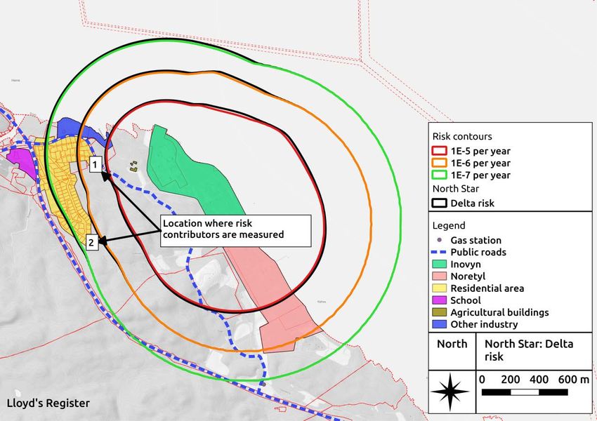
7.4 Individual risk at nearest resident
To further substantiate the discussion above, individual risk due to both the VCM and chlorine plants is
measured at two points located at the nearest residential houses as shown in Figure 7.10.
Figure 7.10 – Locations of the nearest residential houses
Report no: PRJ11090011 Rev: Final Page 24
Date: 11 January 2019 ©Lloyd’s Register 2019The total individual risk at the northernmost of the two locations is 2.88E-06 per year with the North
Star project modifications included. The total risk before including the North Star modifications was
2.58E-06. Hence, the North Star modifications cause an increase in the total risk at this point of
approximately 12 %. Table 7.1 present the largest contributors to the risk at this point before and after
including the North Star modifications. The main risk drivers in this point are the chlorine piping
segments. The modifications do not change the main risk drivers.
Table 7.1 – Risk contribution at resident location#1 before and after the North Star
modifications are included
Model name Description Risk Risk
contribution contribution
before after North
North Star Star
Chlorine KLOR1-003 Rupture of piping/process equipment on 36 % 35 %
RU high-pressure side of chlorine compressor
1
Chlorine KLOR2-003 Rupture of piping/process equipment on 36 % 35 %
RU high-pressure side of chlorine compressor
2
Chlorine KLOR1-001 Rupture of piping/process equipment on 6% 7%
RU chlorine header from cell room 1
Chlorine KLOR1-002 Rupture of piping/process equipment 6% 6%
RU between chlorine dryer and compressor 1
Chlorine KLOR2-001 Rupture of piping/process equipment on 4% 4%
RU chlorine header from cell room 2
Chlorine KLOR2-002 Rupture of piping/process equipment 3% 4%
RU between chlorine dryer and compressor 2
The total individual risk at resident location #2 is 7.09E10-7 per year with the North Star project
modifications included. The total risk before including the North Star modifications was 6.87E-07.
Hence, the North Star modifications cause an increase in the total risk at this point of approximately 3
%. Table 7.2 present the largest contributors to the risk at nearest resident 2 before and after including
the North Star modifications. The main risk driver in this point is a BLEVE event in the VCM storage area.
When the mass flow rate in the piping/process equipment segments is increased due to the North Star
modifications, the contribution to the total risk from the HCl column (V1501) becomes negligible
compared to other segments.
Table 7.2 – Risk contribution at resident location #2 before and after the North Star
modifications are included
Model name Description Risk Risk
contribution contribution
before after North
North Star Star
BLEVE fireball VCM BLEVE in the VCM storage area 70 % 68 %
Chlorine KLOR1-003 Rupture of piping/process equipment on 7% 8%
RU high-pressure side of chlorine compressor
1
Chlorine KLOR2-003 Rupture of piping/process equipment on 7% 8%
RU high-pressure side of chlorine compressor
2
Report no: PRJ11090011 Rev: Final Page 25
Date: 11 January 2019 ©Lloyd’s Register 2019Model name Description Risk Risk
contribution contribution
before after North
North Star Star
1500-HCl-011 RU Rupture of HCl feed to C1501 5% 7%
V1501 RU Rupture of HCl column V1501 4% ~0 %
1600-Cl-017 RU Rupture of the chlorine feed to the LTDC 2% 4%
module
8 Uncertainties
When performing a QRA of a complex industry facility, such as the chlorine and VCM plant at Rafnes, a
number of uncertainties need to be handled. Three categories of uncertainties are discussed to present
the major uncertainties of this study:
1. Uncertainties in parameters and data used as input and modelling assessments, e.g. duration of
process leaks.
2. Uncertainties in modelling tools
3. Uncertainties related to hazards that are not included in the QRA – this could be hazards
deliberately excluded or hazards that are not identified.
There is uncertainty in the use of generic leak scenarios and frequencies. The QRA cannot predict events
that will happen in the plant. The uncertainties are controlled by using a large statistical basis for the
generic data.
The applied modelling tool is a semi-empirical tool, and uses simplified mathematical equations
representing experience of natural phenomena. The modelling tool is verified against large scale tests of
releases of chemical substances. One example of uncertainty is that topography cannot be specifically
modelled.
Leaks from EDC and mixtures with EDC as the main medium are excluded due to the assumption that
release and possible ignition will only give local effects, i.e. within the plant boundary. A few test
releases of EDC have been modelled, albeit not reported, and the gas dispersion distances have been
found minimal. There is, however, a significant uncertainty regarding escalation and if a local fire in an
EDC release can cause equipment failure and release of e.g. HCl or VCM.
9 Potential conservatism in the QRA
This section addresses potential conservatism embedded in the QRA. Note, however, that there are
factors that may not be conservative, such as the exclusion of events with EDC.
9.1 Release durations and transient effects
In general, for process leaks the durations are fixed to either 3 min or 10 min depending on the event.
Also, the release rate is fixed for the duration of the event. For ruptures and large leaks, this can
potentially be conservative. It is typically such events that contribute to the risk contours defining the
risk zones. Hence, it could be worthwhile to investigate if transient effects introduce conservatism.
In order to do so, additional information (or assessment) is needed regarding process segmentation
volumes, flow rates, detection time, initiation of emergency or process shutdown, isolation of segments,
time for closing ESD/PSD valves etc.
Report no: PRJ11090011 Rev: Final Page 26
Date: 11 January 2019 ©Lloyd’s Register 20199.2 Terrain effects
Terrain effects, other than surface roughness, are not captured by the study. The terrain could
potentially provide shielding for some adjacent areas for some of the accidental events (see Figure 9-1).
Chlorine, for example, is a relatively heavy gas compared to air. Hence, it could be expected to follow
the terrain in dispersion scenarios. On the other hand, chlorine is toxic at low concentrations (~50 ppm)
and the terrain may not be that influential once the chlorine is diluted in air. Terrain effects can be
addressed by, e.g., executing CFD simulations of a selected set of scenarios. In addition, the parameter
value for surface roughness applied in the risk model is probably set in a conservative manner.
Figure 9.1 – Risk contours plotted on the terrain around INOVYN’s facility to illustrate the
topography in the area
9.3 Release modelling
The jet direction follows the wind direction in Safeti. This implies that the probability of jet to face the
wind is not included. A jet facing headwind is likely to result in shorter hazard distances. In addition, all
releases are modelled as free, i.e., as non-obstructed jets. In reality, some jets will be pointed
downwards or into process equipment or other obstacles. This will reduce the momentum of the jet,
leading to shorter hazard distances.
9.4 Event frequencies
One could consider adapting the event frequencies for the facility, if INOVYN has historic data over
accidental events.
9.5 BLEVE
A major risk driver for the VCM plant is BLEVE events with the VCM storage tanks; cf. Figure 7.5 in
Section 7.3. The BLEVE frequency is based on the fire frequency in the relevant area and a probability of
failure on demand of the deluge system (see Appendix A). However, fire water can also be supplied by
fire trucks and other means, which has not been credited. Also, the durations of the initial fires may be
too short to cause a BLEVE. Hence, the BLEVE event frequency might be conservative, and could be
investigated further in subsequent studies.
9.6 Flash fire envelope
The main risk drivers are not flash fires. Still, there is some conservatism in the model with respect to
how flash fire risks are modelled. The lethality range of a flash fire is linked to the extent of the 50%LFL
cloud size. With the new QRA guidelines (Ref. /10/), this would typically be reduced to 100%LFL.
Report no: PRJ11090011 Rev: Final Page 27
Date: 11 January 2019 ©Lloyd’s Register 201910 Conclusion and recommendations
10.1 Recommendations
It is recommended to address potential conservatism in the risk model in the next revision of the QRA.
Section 9 above lists some aspects to investigate in that respect. Following such an update one can look
into potential risk reducing measures. For example, avoiding a BLEVE event is obviously important, and if
there is a potential to reduce the risk of such an event, this could be addressed in the update. Risk
reducing measures regarding toxic releases could also be discussed.
One new process module, the HTDC module, is installed as part of the North Star project. A measure to
potentially reduce the probability of escalation from an accident in this module has been briefly
discussed in this report, i.e. the cooling effect of fire water. If INOVYN is uncomfortable with this
assessment, more detail studies can be executed to quantify the escalation potential.
For completeness, the recommendations from the existing QRA are included. These are:
• It is recommended to further develop and maintain systems and procedures to ensure fast detection
and minimisation of duration of a release in case of an accidental scenario involving chlorine gas
• Emergency preparedness and quick notification (alarm) to the public to move indoors and close all
doors and windows are essential to avoid severe 3rd party injuries, in case of a large toxic release
• INOVYN needs to make sure that the risk from the Chlorine and VCM plant are ALARP, As Low As
Reasonably Practicable.
10.2 Conclusions
Overall, the North Star project does not contribute with a significant risk increase compared to the
existing risk picture at INOVYN’s facility at Rafnes. The main risk drivers remain unchanged from the
existing QRA. Hence, toxic releases and BLEVE events in the VCM storage area dominate the risk picture
and are dimensioning for the risk contours that will define the risk zones around the facility.
When comparing the calculated total risk picture for the chlorine and VCM plant at Rafnes against the
DSB suggested RAC (Ref. /8/), the following are noted:
• Public roads and neighbouring industries are within the 1E-5 per year risk contour
• Parts of the neighbouring residential area are within the 1E-6 per year risk contour. However,
scattered houses may be permitted within the 1E-6 per year risk curve under certain circumstances.
The North Star modifications do not cause any changes to the risk picture with respect to the suggested
RAC.
Report no: PRJ11090011 Rev: Final Page 28
Date: 11 January 2019 ©Lloyd’s Register 2019You can also read