NRA Series Remote Analyzer - Operating Manual / Bedienungsanleitung - Narda Safety Test Solutions
←
→
Page content transcription
If your browser does not render page correctly, please read the page content below
NRA Series
Remote Analyzer

Operating Manual /
Bedienungsanleitung


NRA Series
Remote Analyzer

Operating Manual
Narda Safety Test Solutions GmbH
Sandwiesenstrasse 7
72793 Pfullingen, Germany
© 2022
® Names and Logo are registered trademarks of
Narda Safety Test Solutions GmbH - Trade
names are trademarks of the owners.

Order no.: 3200/98.11
Issue: 01/18/2022
Previous issue: 11/16/2015

Subject to change.
Our normal guarantee and delivery terms apply.
Printed in Germany
Contents

Contents
           1   Introduction.............................................................................. 3
               1.1        About this device............................................................................. 4
               1.1.1      NRA-2500 ........................................................................................ 4
               1.1.2      NRA-3000 RX .................................................................................. 4
               1.1.3      NRA-6000 RX .................................................................................. 4
               1.2        About this operating manual ........................................................... 5
               1.2.1      Symbols and terms used in warnings .............................................. 5
               1.2.2      Warning format ................................................................................ 5
               1.2.3      Symbols and characters .................................................................. 6

           2   Important safety instructions ................................................. 7
               2.1        Using this operating manual ........................................................... 8
               2.2        Before connecting up ...................................................................... 8
               2.3        Proper use ...................................................................................... 8
               2.4        Improper use ................................................................................... 8
               2.5        General hazards ............................................................................. 8
               2.6        Faults and unusual stresses ......................................................... 10

           3   Overview / Fitting / Connecting ............................................ 11
               3.1        Unpacking ..................................................................................... 12
               3.1.1      Packaging ...................................................................................... 12
               3.1.2      Package contents .......................................................................... 12
               3.1.3      Checking the device for shipping damage ..................................... 12
               3.1.4      Recovery after shipping and storage ............................................. 12
               3.2        Device overview ............................................................................ 13
               3.3        Symbols on the device .................................................................. 14
               3.4        Rack mounting .............................................................................. 14
               3.5        Connecting up ............................................................................... 15

           4   Getting started ....................................................................... 17
               4.1        General information ...................................................................... 18
               4.1.1      USB connection via virtual COM port ............................................ 18
               4.1.2      Ethernet link using crossover cable ............................................... 18
               4.1.3      Ethernet link via a network ............................................................. 19
               4.2        Switching on .................................................................................. 19
               4.3        Self test / Error codes ................................................................... 19
               4.4        Determining remote interface ready status ................................... 20
               4.5        USB connection ............................................................................ 20
               4.6        Firmware-Update .......................................................................... 21
               4.7        Network configuration ................................................................... 21

Narda                                NRA Series                                                                            1
Contents
4.8 Auxiliary and demo applications ................................................... 22
4.8.1 NRA Configurator and Device Finder ............................................ 22
4.8.2 NRA Tools ...................................................................................... 22
4.8.3 Demo applications ......................................................................... 22
4.8.4 Web server ..................................................................................... 22
5 Special functions ................................................................... 23
5.1 Antenna Control function description ............................................ 23
5.2 10 MHz reference input................................................................. 23
6 Cleaning / Maintenance / Repairs / Disposal ....................... 25
6.1 Cleaning ........................................................................................ 26
6.2 Maintenance and repairs .............................................................. 26
6.3 Replacing the fuse ........................................................................ 26
6.4 Correct disposal ............................................................................ 27
7 Remote Control ...................................................................... 28
8 Specifications ........................................................................ 30
8.1 Definitions and Conditions ............................................................ 31
8.2 Frequency ranges and modes ...................................................... 32
8.3 RF features ................................................................................... 32
8.3.1 Frequency ...................................................................................... 32
8.3.2 Amplitude ....................................................................................... 32
8.3.3 RF input ......................................................................................... 33
8.4 Spectrum analysis......................................................................... 33
8.5 Multi channel power (option) ......................................................... 33
8.6 Level meter (option) ...................................................................... 34
8.7 Scope and I/Q Data (option) ......................................................... 34
8.8 General specifications................................................................... 35
8.9 Declaration of origin ...................................................................... 35
8.10 CE Declaration of Conformity ....................................................... 36
9 Order information .................................................................. 37
9.1 Device versions............................................................................. 38
9.2 Options .......................................................................................... 38
10 Glossary ................................................................................. 39
2 NRA Series Narda1 Introduction
1 Introduction
This chapter contains basic information about using the NRA and about the structure of this
Operating Manual.
1.1 About this device (page 4)
1.2 About this operating manual (page 5)
Narda NRA Series 31 Introduction
1.1 About this device
The remote-controlled Analyzer NRA (Narda Remote Analyzer) is intended for measuring
and analyzing as well as short- and long-term monitoring of all types of RF signals. The NRA
is available in three versions, NRA-2500, NRA-3000 RX and NRA-6000 RX, which meet the
requirements of applications in satellite communications, broadcasting, and
telecommunications. Optional extras allow users to adapt the range of functions to suit
individual needs.
The NRA is a rack-mounted unit fitted into a rugged 19” casing just one unit in height
(1 HU = 1.75"). The device is characterized by its low power consumption of less than 20 W,
which means that it also generates very little waste heat. The use of a precision heterodyne
receiver coupled with modern digital signal processing means that the NRA can make
accurate measurements very quickly. The NRA RX models ensure better RF properties and
are specifically tailored to the Radio Monitoring the market.
Operation and remote control of the NRA is by means of an ASCII-based command set that
allows very efficient programming. All the available commands are described in detail in the
NRA Command Reference Guide, which also contains comprehensively documented
command sequences that make it easier to efficiently develop programs for remote control
and operation of the device.
1.1.1 NRA-2500
The NRA-2500 is a cost-effective entry level analyzer especially developed for
measurement tasks in the field of satellite communications (SatCom). Its 5 MHz to
2500 MHz frequency range is tailored to the L-Band, allowing the NRA-2500 to monitor the
intermediate frequencies and reference signals commonly used in satellite communications.
1.1.2 NRA-3000 RX
The NRA-3000 RX is an analyzer with receiver performance and is particularly suitable for
measurement tasks involving broadcasting equipment. Signals with frequencies up to 3 GHz
can be measured, and the maximum input level of +20 dBm means that the NRA-3000 RX
can also handle the higher signal levels that are typically encountered in the field of
broadcasting.
1.1.3 NRA-6000 RX
The NRA-6000 RX is an analyzer with receiver performance and extended frequency range
especially useful for measurements in telecommunications, such as wireless services up to
6 GHz. With its extremely large resolution bandwidth of up to 20 MHz, the NRA-6000 RX
covers the entire frequency spectrum from 9 kHz up to 6 GHz. Here too, high input levels of
up to +20 dBm can be measured and analyzed.
4 NRA Series Narda1 Introduction
1.2 About this operating manual
Various elements are used in this operating manual to indicate special meanings or
particularly important instructions.
1.2.1 Symbols and terms used in warnings
The following warnings, symbols and terms are used in this document in compliance with
the American National Standard ANSI Z535.6-2006:
This general danger symbol in conjunction with the terms
CAUTION, WARNING, or DANGER warns of the risk of severe
injury. Follow all subsequent instructions to avoid injury or death.
Indicates a danger that could lead to damage or destruction of
NOTICE the device.
CAUTION Indicates a danger that represents a low or medium risk of injury.
WARNING Indicates a danger that could lead to death or severe injury.
DANGER Indicates a danger that will result in death or severe injury.
1.2.2 Warning format
All warnings have the following format:
WARNING TERM
Type and source of danger
Consequences of ignoring the warning
► Action needed to avoid danger
Narda NRA Series 51 Introduction
1.2.3 Symbols and characters
Requirement
Indicates a requirement that must be fulfilled before the subsequent action
can be taken. Example:
The measurement screen is displayed.
► Action
Indicates a single action. Example:
► Switch the device on.
1. Sequence of actions
2. Indicates a sequence of actions that must be performed in the order given.
3.
Result
Indicates the result of an action. Example:
The device starts a self test.
Bold text Control element or menu name
Indicates device control elements and menu names. Example:
► Press the OK key.
Note: Important additional information or details of special features or situations.
6 NRA Series Narda2 Important safety instructions
2 Important safety instructions
This chapter contains important information on how to handle the device safely.
2.1 Using this operating manual (page 8)
2.2 Before connecting up (page 8)
2.3 Proper use (page 8)
2.4 Improper use (page 8)
2.5 General hazards (page 8)
2.6 Faults and unusual stresses (page 10)
Narda NRA Series 72 Important safety instructions
2.1 Using this operating manual
► Please read this manual carefully and completely before using the device.
► Keep this manual so that it is readily available to all users of the device.
► Always make sure that this manual accompanies the device if it is given to a third party.
2.2 Before connecting up
The device left the factory in perfect condition. We recommend that the following instructions
be followed to ensure that this condition is maintained and that operation of the device is
without danger.
2.3 Proper use
The device may only be used under the conditions and for the purpose for which it was
constructed. The NRA is designed for measuring and analyzing high frequency electrical
signals.
► Only use the device under the conditions and for the purpose for which it was
constructed.
► The device must only be used indoors and in dry conditions.
► Do not exceed the maximum permitted signal level for the device.
Proper use also includes the following:
► Following the national accident prevention rules that apply at the place of use.
► Only allowing appropriately qualified and trained persons to use the device.
2.4 Improper use
The device must not be used outdoors.
2.5 General hazards
WARNING
Electric shock
High voltages are present inside the device.
► Do not open the device. (Opening the device invalidates all claims under warranty.)
► Do not handle the opened device or a device which is visibly damaged.
► Only use the accessories designed for the NRA and supplied with the device.
8 NRA Series Narda2 Important safety instructions
WARNING
Electric shock from liquid entering the device
If liquid gets inside the device casing, there is a danger of potentially fatal electric
shock and the device may be damaged or destroyed.
► Make sure that no liquid can get into the device.
WARNING
Overvoltage
Incorrect connectors and excessive voltages adversely affect the safety of the
device and can endanger the user.
► This device is intended for use with the fixed electrical installation within a building
complying with IEC 61010-1 overvoltage category II. Only use the device under the
conditions specified in this standard.
► The inputs are not rated for connection to mains or overvoltage category II, III or IV
circuits.
WARNING
Safety and malfunction
Improper use, damage, and unauthorized repairs can affect the safety and function
of the device.
► Only use the device under the conditions and for the purpose for which it was
designed.
► Check the device for damage regularly.
► Make sure that any repairs are made only by qualified persons.
CAUTION
Hot connector sockets
The connecting sockets (RF IN) on the back panel can get very warm if the device is
used for long periods. This is normal.
► Please be careful when touching the connectors after using the device for a long period
of time.
NOTICE
Overheating in rack
Fitting the device in an unventilated rack may result in malfunctioning and damage.
► Make sure that the device is operated within the ambient temperature range stated in
the specifications.
► Make sure that there is adequate space around the device and that there is sufficient
ventilation.
Narda NRA Series 92 Important safety instructions
2.6 Faults and unusual stresses
Take the device out of service and secure it against unauthorized use if it can no longer be
used safely, for example as in the following situations:
• The device is visibly damaged.
• The device does not work anymore.
Contact your local Sales Partner for assistance in such cases.
10 NRA Series Narda3 Overview / Fitting / Connecting
3 Overview / Fitting / Connecting
This chapter contains an overview of the NRA and describes how to fit it in a rack and how
to connect it up.
3.1 Unpacking (page 12)
3.2 Device overview (page 13)
3.3 Symbols on the device (page 14)
3.4 Rack mounting (page 14)
3.5 Connecting up (page 15)
Narda NRA Series 113 Overview / Fitting / Connecting
3.1 Unpacking
3.1.1 Packaging
The packaging is designed to be re-used as long as it has not been damaged during
previous shipping. Please keep the original packaging and use it again whenever the device
is shipped.
3.1.2 Package contents
Carefully remove all items from the packaging and check that all items are correct:
• NRA version as ordered
• Support CD
• USB cable
• AC line cord (according to country)
• Test certificate
• NRA Operating Manual
• NRA Command Reference Guide
3.1.3 Checking the device for shipping damage
After unpacking, check the device and all accessories for any damage that may have
occurred during shipping. Damage may have occurred if the packaging itself has been
clearly damaged. Do not attempt to use a device that has been damaged.
3.1.4 Recovery after shipping and storage
Condensation can form on a device that has been stored or shipped at a low temperature
when it is brought into a warmer environment. To prevent damage, wait until all
condensation on the surface of the device has evaporated. The device is not ready for use
until it has reached a temperature that is within the guaranteed operating range of
-10 to +50 °C.
12 NRA Series Narda3 Overview / Fitting / Connecting
3.2 Device overview
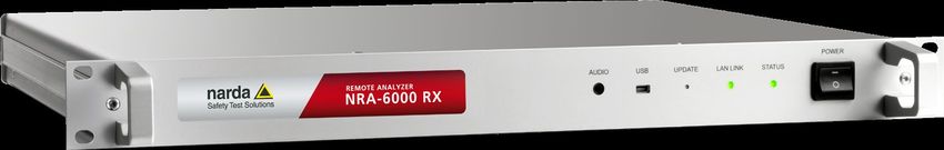
Figure 1: Overview of front and back panels
Nr. Element Function / Description
1 Label- Device Version
Device Each device version has its own Label.
versions
2 Audio 3,5 – Jack socket
For listening to demodulated analog signals.
3 USB Mini USB connector
4 UPDATE Activates a firmware update
Information on updating the firmware is found in chapter 4.6 on
page 21.
5 LAN LINK Network connection
• LED glows green: Network connection detected
• LED flashes green: Data transfer
6 STATUS Device status
• Start up phase 1: LED glows red = System start
• Start up phase 2: LED glows orange = Self test
• Start up phase 3: LED glows red = Loading program
• Start up phase 4: LED glows green = Ready
*If an error occurs during the self test, the LED will flash red. The
number of flashes indicates the type of error. Information about the
error codes is found in chapter 4.3 on page 19.
7 POWER AC power switch
The device is disconnected from AC power when the switch is set
to 0.
8 Power AC power socket and fuses
The fuses are in the fuse holder directly underneath the AC line
socket.
9 Option – Options information
Label Listing of ordered Soft- and Hardware options.
10 Ethernet RJ45 Ethernet connector
11 10 MHz IN BNC - Socket for 10 MHz-Referenz-Input
To connect an external reference signal. Technical parameter:
Ze = 600 Ohm; Ue = 0,1 Vss bis 3 Vss, max 10 VDC.
12 Ant-Ctrl Antenna Control
(Option) Capability to control Narda-STS antennas and cables.
13 RF IN 50 Ω Signal input connector, 50 Ω N connector
14 Type label Device identification (type, serial number)
Narda NRA Series 133 Overview / Fitting / Connecting
3.3 Symbols on the device
Symbol Description
Refer to operating manual
The operating manual contains important information about items marked with
the general warning symbol.
Compliance
Hereby, Narda STS declares that this equipment is in compliance with the
directives 2014/30/EU, EN61326-1:2013, 2014/35/EU, EN61010-1:2010, and
2011/65/EU.
The full text of the EU declaration of conformity is available at www.narda-
sts.com.
Separate disposal
This symbol indicates that the device must be disposed of separately from
household waste. For further information see 6.4 Correct disposal on page 27.
3.4 Rack mounting
The device is designed to be mounted in a 19” rack.
► Make sure the device is secure when mounting it in the rack.
NOTICE
Overheating in rack
Fitting the device in an unventilated rack may result in malfunctioning and damage.
► Make sure that the device is operated within the ambient temperature range stated in
the specifications.
► Make sure that there is adequate space around the device and that there is sufficient
ventilation.
14 NRA Series Narda3 Overview / Fitting / Connecting
3.5 Connecting up
WARNING
Electric shock risk if device not grounded
Operating this device from an AC line outlet without a ground connection can lead
to a potentially fatal electric shock.
► Use only the AC line cord supplied with the device.
► Do not use the AC line cord if it is damaged.
► Do not connect the device to any AC power outlet that is not equipped with a protective
ground.
NOTICE
Inaccessible AC line switch
The device must be disconnected from the AC line by means of the AC power
switch in an emergency.
► Make sure that you set up the device so that the AC power switch is easily accessible
at all times.
To connect up the device:
► Connect the device to the network using the Ethernet connection (Figure 1: 7).
or
Connect the device to a PC using the USB connection (Figure 1: 1).
► Connect the AC power input on the device (Figure 1: 6) to the AC power supply using the
AC power cord supplied with the device.
Narda NRA Series 153 Overview / Fitting / Connecting 16 NRA Series Narda
4 Getting started

4       Getting started

        This chapter describes how to start using the device.

        4.1    General information (page 18)

        4.2    Switching on (page 19)

        4.3    Self test / Error codes (page 19)

        4.4    Determining remote interface ready status (page 20)

        4.5    USB connection (page 20)

        4.6    Firmware-Update (page 21)

        4.7    Network configuration (page 21)

        4.8    Auxiliary and demo applications (page 22)

Narda                             NRA Series                                       17
4 Getting started
4.1 General information
The device can be addressed for control via the remote interface by means of a USB
connection and / or an Ethernet (TCP/UDP) connection. The USB interface appears as a so-
called virtual COM port on the PC and allows simple handling just like the usual serial
interface. The NRA internal TCP server allows connection to a client for exchanging data.
The IP address and the remote port of the TCP server must be known in order to set up the
Ethernet link. The IP address and port together with the communication protocol are also
called the socket interface.
The entire range of functions is available via the remote interface. You can set all the
measurement parameters and read out the measurement results cyclically.
NOTE: Every command sent to the remote device generates a response. The time taken for the
response to come from the remote device depends greatly on the type of command.
Commands received in parallel (e.g. from USB and Ethernet) are processed sequentially in
the remote device.
4.1.1 USB connection via virtual COM port
One USB client is always connected to the USB host via the USB connection.
No provision has been made for multiple client connections to one remote device. The USB
connection is used primarily to configure the remote device.
4.1.2 Ethernet link using crossover cable
You can directly connect a remote device to a computer using a crossover network cable.
Static IP addresses must be assigned to the client and the server for this, as the remote
device is not equipped with a DHCP server. In this instance, only one client can be
connected to the TCP server of the remote device.
18 NRA Series Narda4 Getting started
4.1.3 Ethernet link via a network
Indirect access via a network is achieved by connecting the remote device to a network. The
IP address can be assigned dynamically by a DHCP server (e.g. built in to a router) or
statically. A plain Ethernet (patch) cable is required.
4.2 Switching on
Make sure that all the connections have been made correctly
(see Chapter 3.5 on page 15).
► Switch the device on using the AC power switch:
Start up phase 1: Status LED glows red = System start
Start up phase 2: Status LED glows orange = Self test*
Start up phase 3: Status LED glows red = Loading program
Start up phase 4: Status LED glows green = Ready
If the Ready status is not indicated within about 1 minute:
► Switch the device off and then repeat the switch on process.
NOTE: If the device repeatedly does not switch on, please contact your local representative for
Narda products.
*If an error occurs during the self test, the LED will flash red. The number of flashes
indicates the type of error. Information about the error codes is found in the next section.
4.3 Self test / Error codes
If an error occurs during the self test, the LED will flash red. The number of flashes indicates
the type of error. The sequence of flashes is repeated three times at intervals of three
seconds.
Table 1: Error codes
Number of Error
flashes
1 Operating system
2 Hardware
3 Memory
4 Data Logger
5 Flash
Narda NRA Series 194 Getting started
4.4 Determining remote interface ready status
The Status LED glows green as soon as the boot process is completed and the
communication function is working for the remote interfaces (USB / Ethernet). This process
takes at least 20 seconds.
To check the communications function of the remote interface(s) it is a good idea to keep
transmitting the REMOTE?; command until the device responds.
4.5 USB connection
The USB connection can be used for the following tasks:
• Configuring the device
• Uploading firmware updates
• Monitoring (retrieving the measurement screen)
NOTE: The USB connection is of only limited use for controlling measurements because the input
is not electrically decoupled. Only use the Ethernet connection for controlling
measurements to ensure that the specifications are not impaired.
You will have to install the USB driver for the device before you can use the USB
connection.
► To do this, start the Setup program (setup.exe) from the USB_Driver_NRA folder on the
Support CD. Instead, you can also install NRA Tools (includes the driver installation).
On successful installation of the USB connection, a (virtual) COM port is shown in the
Device Manager of the host computer. Communication with the device is via this virtual
COM port which acts just like a normal serial interface.
The following interface parameters are used:
Table 2: USB interface parameters
Parameter Settings
Baud rate 115200 Baud
Start bits 1
Data bits 8
Stop bits 1
Parity None
Handshake None
20 NRA Series Narda4 Getting started
4.6 Firmware-Update
NOTE: The firmware can only be updated via the USB interface. Information about the latest
firmware updates can be found on the NRA product web page (www.narda-nra.com).
To update the firmware:
1. Install the program NRA Tools from the Support CD on your PC.
2. Download the zipped update file from the NRA product web page and unzip the file on
your PC.
3. Connect the NRA to a free USB socket on your PC and start NRA Tools.
4. Go to the Options Menu, click on the firmware update icon and follow the instructions of
the program.
To activate update mode on the NRA: Use e.g. the tip of a ballpoint pen to press and
hold down button (Figure 1: 4) on the front panel and switch the device on using the AC
power switch (Figure 1: 7).
The Status LED (Figure 1: 6) glows red continuously in Update mode.
4.7 Network configuration
The device operates as a TCP server and can accept a connection to a client.
► When starting up, make sure that the device is in the same subnet as the operating
computer and that there are no firewalls or other network components that might prevent
data communications.
A DHCP server (e.g. in the form of a router) must be present in the network if automatic IP
address assignment (DHCP service) is to be used.
The default settings are shown in the table below.
Table 3: Default parameters for TCP server network configuration
Parameter Default settings
DHCP OFF
IP address 192.168.128.128
Subnet mask 255.255.255.0
Gateway No default Gateway
TCP port 55555
NOTE: If you want to use settings other than the default settings, you can use the „NRA Tools“
application on the Support CD for this purpose.
Narda NRA Series 214 Getting started
4.8 Auxiliary and demo applications
This section gives a brief summary of the auxiliary and demo applications that are on the
Support CD. The applications are described in detail in electronic form on the Support CD.
4.8.1 NRA Configurator and Device Finder
The Configurator is primarily intended for network configuration of the device.
The Device Finder is intended for detecting NRA devices and its IP addresses in the
network (this function is not available for USB).
4.8.2 NRA Tools
NRA Tools is for activating new options by key code and managing firmware updates of the
device. Furthermore, external devices, antennas and cables can be added and configured.
The NRA Tools installation also includes the installation of the USB driver and NRA
Configurator.
The user interface provides direct access to the NRA Configurator for IP address
configurations.
For devices with activated Multi Channel Power Option, NRA Tools is useful to create and
transfer MCP tables.
4.8.3 Demo applications
The demo applications on the Support CD have the following features:
• They demonstrate the performance of the remote interface of the device.
• They help you in taking the first steps in familiarizing yourself with the device.
• Separate demo applications are available for each operating mode.
4.8.4 Web server
The web server is an integral part of the NRA device with the following functions:
• It enables communication with the device using a standard web browser.
• No PC application installation is required.
• It enables access to the HTML pages stored in the device.
• Java applets are being used.
• Web applications “NRA Web Terminal” and “NRA Live Display Viewer” based on Java
Applets and HTML.
• For web terminal Java “Version 7 Update 79” or previous version required.
22 NRA Series Narda5 Special functions
5 Special functions
This chapter describes special functions of the device. These functions may only be
available in certain device versions.
5.1 Antenna Control function description
The NRA series provides an optional Ant-CTRL. With this connector a Narda antenna can
be connected, correction values can be read and the antenna can be controlled. The same
applies to the extension cord from Narda.
The individual commands to control the antennas and cables can be found in the NRA
Command Reference Guide under the heading “Antenna and Cable” and “Axis
Commands“.
5.2 10 MHz reference input
The NRA Series provides a 10 MHz reference input. With this reference input it is possible
to synchronize the internal reference clock with an external signal source. The external
reference source must comply with following parameters:
Z = 600 Ohm; U = 0,1 Vpp bis 3 Vpp, max 10 VDC. The external 10 MHz reference signal
will be connected over a BNC socket.
The individual commands to control the 10 MHz Reference Input can be found in the NRA
“Command Reference Guide” under the heading “Reference Input 10 MHz“.
Narda NRA Series 235 Special functions 24 NRA Series Narda
6 Cleaning / Maintenance / Repairs / Disposal

6       Cleaning / Maintenance /
        Repairs / Disposal

        This chapter contains information about how to clean the device, how to replace the fuses,
        and how to dispose of the device when it is to be scrapped.

        6.1    Cleaning (page 26)

        6.2    Maintenance and repairs (page 26)

        6.3    Replacing the fuse (page 26)

        6.4    Correct disposal (page 27)

Narda                             NRA Series                                                     25
6 Cleaning / Maintenance / Repairs / Disposal
6.1 Cleaning
WARNING
Electric shock risk from liquid entering the device
Liquid getting inside the device casing can lead to a potentially fatal electric shock
and can damage or destroy the device.
► Do not let water or cleaning fluid get inside the device.
► Use only a slightly damp cloth for cleaning the device.
6.2 Maintenance and repairs
There are no user-replaceable or serviceable parts in the device.
► Please contact your local representative for Narda products in the event of a problem.
6.3 Replacing the fuse
Both phases of the AC supply to the device are fuse protected. Both the fuses
(size 5 x 20 mm) are located in the fuse holder directly underneath the AC line connector on
the back panel of the device:
1
Figure 2: Fuses are located underneath the AC line connector.
To change the fuses:
1. Switch off the device using the AC power switch, and unplug the AC line cord from the
device.
2. Use a small screwdriver to lift out the fuse holder (1).
3. Remove the defective fuse or fuses and replace it or them with fuses of the same type
and rating. Information about the correct type of fuse is printed on the back panel of the
device.
4. Push the fuse holder back in to the casing, reconnect the AC line cord, and switch the
device on again.
26 NRA Series Narda6 Cleaning / Maintenance / Repairs / Disposal
6.4 Correct disposal
6.4.1 Disposal of used equipment
The crossed-out wheeled garbage can symbol indicates that this product is subject to the
European WEEE Directive 2012/19/EU on the disposal of waste electrical and electronic
equipment and must be disposed of separately from household waste in accordance with
your national regulations.
In the European Union, all electronic measuring systems purchased from Narda after August
13, 2005 can be returned at the end of their useful life.
► For more information, please contact your Narda distributor.
6.4.2 Disposal of removable batteries
Batteries must not be disposed of in household waste, but must be disposed of separately
from the product in accordance with the applicable regulations. They can be returned free of
charge to the appropriate collection points, your dealer or directly via Narda.
► Please discharge the batteries before disposal.
6.4.3 Disposal of permanently installed batteries
There are no permanently installed batteries in this device.
6.4.4 Deleting private data
Make sure that you delete any stored private data before passing on or disposing of the
device.
Narda NRA Series 277 Remote Control
7 Remote Control
Detailed information about remote control together with descriptions of the remote control
commands and application examples can be found in the separate Command Reference
Guide supplied with the device.
28 NRA Series Narda7 Remote Control Narda NRA Series 29
8 Specifications

8                  Specifications

                   This chapter contains the specifications of the NRA.

                   Unless otherwise stated, the quoted specifications apply only within the temperature range
                   20 °C to 26 °C and relative humidity between 25 % and 75 %.
                   The device must be switched on for at least 30 minutes before the specifications can be
                   checked. All specifications are valid only for remote control using the Ethernet interface.

                   All data are subject to change without notice.

                   The technical specifications may change due to product developments. The latest technical
                   specifications can be found in the datasheet of the product. The datasheet can be
                   downloaded from the Narda website www.narda-sts.com under the corresponding product
                   page.

                   8.1    Definitions and Conditions (page 31)

                   8.2    Frequency ranges and modes (page32)

                   8.3    RF features (page32)

                   8.4    Spectrum analysis (page 33)

                   8.5    Multi channel power (option) (page 33)

                   8.6    Level meter (option) (page 34)

                   8.7    Scope and I/Q Data (option) (page 34)

                   8.8    General specifications (page 35)

                   8.9    Declaration of origin (page 35)

                   8.10   CE Declaration of Conformity (page 36)

30                                           NRA Series                                                   Narda
8 Specifications
8.1 Definitions and Conditions
Conditions
Unless otherwise noted, specifications apply after 30 minutes warm-up time within the
specified environmental conditions. The product is within the recommended calibration
cycle.
Specifications with limits
These describe product performance for the given parameter covered by warranty.
Specifications with limits (marked as , ≥, ±, max., min.) apply under the given
conditions for the product and are tested during production taking measurement uncertainty
into account.
Specifications without limits
These describe product performance for the given parameter covered by warranty.
Specifications without limits represent values with negligible deviations which are ensured
by design (e.g. dimensions or resolution of a setting parameter).
Typical values (typ.)
These characterize product performance for the given parameter that is not covered by
warranty. When stated as a range or as a limit (marked as , ≥, ±, max., min.), they
represent the performance met by approximately 80 % of the instruments. Otherwise, they
represent the mean value. The measurement uncertainty is not taken into account.
Nominal values (nom.)
These characterize expected product performance for the given parameter that is not
covered by warranty. Nominal values are verified during product development but are not
tested during production.
Uncertainties
These characterize an interval for a given measurand estimated to have a level of
confidence of approximately 95 percent. Uncertainty is stated as the standard uncertainty
multiplied by the coverage factor k=2 based on the normal distribution. The evaluation has
been carried out in accordance with the rules of the "Guide of the Expression of Uncertainty
in Measurement" (GUM).
Narda NRA Series 318 Specifications
8.2 Frequency ranges and modes
NRA-2500 NRA-3000 RX NRA-6000 RX
9 kHz to 3 GHz
Frequency range 5 MHz to 2.5 GHz 9 kHz to 6 GHz
Spectrum Analysis
Spectrum Analysis
Multi Channel Power (option)
Modes Multi Channel Power (option)
Level Meter (option)
Level Meter (option)
Scope and I/Q (option)
8.3 RF features
8.3.1 Frequency
NRA-2500 NRA-3000 RX NRA-6000 RX
Resolution bandwidth (RBW) See specifications for each mode
fc df= 10 kHz df=100kHz
Phase noise 57,5 MHz ≤ -121 dBc/Hz ≤ -126 dBc/Hz
(SSB) 2,1405 GHz ≤ -92 dBc/Hz ≤ -100 dBc/Hz
4,5005 GHz ≤ -97 dBc/Hz ≤ -100 dBc/Hz
Initial deviation: < 1 ppm
Reference frequency Aging: < 1 ppm/year (< 5 ppm over 15 years)
Thermal drift: < 1.5 ppm (within temperature range -10 °C to 50 °C)
8.3.2 Amplitude
NRA-2500 NRA-3000 RX NRA-6000 RX
Reference level RL -30 dBm to 0 dBm -30 dBm to +20 dBm
(in 1 dB steps)
From Displayed Average
Display range From Displayed Average Noise Level (DANL) to +20 dBm
Noise Level (DANL) to 0 dBm
RF attenuation
0 to 30 dB in steps of 1 dB 0 to 50 dB in steps of 1 dB
(coupled with RL)
Maximum RF power level +27 dBm (destruction limit)
Maximum DC voltage 50 V
f ≤ 50 MHz: < -160 dBm/Hz (noise figure < 14 dB)
f ≤ 2 GHz: < -156 dBm/Hz (noise figure < 18 dB)
Display Average Noise Level (DANL) < -140 dBm/Hz
for RL=-30 dBm (input attn = 0 dB) (noise figure < 34 dB) f ≤ 4 GHz: < -155 dBm/Hz
f ≤ 3 GHz: < -155 dBm/Hz (noise figure < 19 dB)
(noise figure < 19 dB) f ≤ 6 GHz: < -150 dBm/Hz
(noise figure < 24 dB)
< -76 dBc for two single tones with a level of 6 dB below RL,
f ≤ 50 MHz: spaced by 1 MHz or more
3rd order intermodulation IP3 ≥ +22 dBm (@ RL = -10 dBm)
(IP3) < -60 dBc for two single tones with a level of 6 dB below RL,
f > 50 MHz: spaced by 1 MHz or more
IP3 ≥ +14 dBm (@ RL = -10 dBm)
Extended level measurement < ± 1.5 dB (15 °C to 30 °C) < ± 1.2 dB (within temperature range 15 °C to 30 °C)
uncertainty b)
< ± 2.3 dB (-10 °C to 50 °C) < ± 2.0 dB (within temperature range -10 °C to 50 °C)
32 NRA Series Narda8 Specifications
Spurious responses
< -50 dBc or RL -50 dB < -60 dBc or RL -60 dB
(input related) c), d)
Spurious responses (residual) < -80 dBm < -90 dBm
for RL=-30 dBm (input att = 0 dB)
b) 95 % confidence level, includes absolute uncertainty, frequency response in all RL settings and temp. response. Valid for Spectrum and MCP mode.
c) Carrier offset of ≥100 kHz
d) Whichever is worse
8.3.3 RF input
NRA-2500 NRA-3000 RX NRA-6000 RX
Type N-connector, 50 Ω
Return loss (typ.) > 12 dB for f ≤ 4.5 GHz
> 10 dB > 12 dB
for RL ≥ -28 dBm (input attn ≥ 2 dB) > 10 dB for f > 4.5 GHz
8.4 Spectrum analysis
NRA-2500 NRA-3000 RX NRA-6000 RX
Frequency span 10 kHz to 2.495 GHz 1 kHz to 2.999 GHz 1 kHz to 5.999 GHz
Measurement principle Spectrum analysis with up to 600.000 samples (bins) per Result Type and Sweep
Set individually from a list or using the “RL Search” function
Reference level setting (RL)
for determining the optimum measurement range at a given time
Resolution bandwidths RBW 1 kHz to 1 MHz 10 Hz to 20 MHz
(-3 dB nominal) (in steps of 1, 2, 3, 5,10,20...) (in steps of 1, 2, 3, 5, 10, 20, …)
Video bandwidth (VBW) Off, 0.2 Hz to 2 MHz (depending on the selected RBW)
ASCII: < 21 ms (@ RBW = 0.5 MHz, 201 bins)
50 MHz Span
Sweep time BINARY: < 17 ms (@ RBW = 0.5 MHz, 201 bins)
(typ.)
ASCII: < 119 ms (@ RBW = 1 MHz, 2001 bins)
1 GHz Span
BINARY: < 88 ms (@ RBW = 1 MHz, 2001 bins)
including
communication ASCII: < 875 ms
over Ethernet 6 GHz Span NA NA BINARY: < 500 ms
(@ RBW = 0.5 MHz, 24001 bins)
Type Gaussian
Filter
Shape factor
< 3.8 (typ.)
(-3 dB / 60 dB)
ACT: Displays current (actual) spectrum
MAX: Maximum hold function
AVG: Average over a selectable number of spectra (4 to 256)
Result Type or a selectable time period (1 to 30 minutes)
Max AVG: Maximum hold function after averaging over a defined number of spectra
Min: Minimum hold function
Min AVG: Minimum hold function after averaging over a defined number of spectra
8.5 Multi channel power (option)
NRA-2500 NRA-3000 RX NRA-6000 RX
Spectrum analysis, followed by Channel Power evaluation
Measurement principle
(Number of Channels 1 to 500)
Channel band width (CBW)
Individually selectable for each channel, from 40 Hz to 6 GHz
(-3 dB nominal)
Roll-off factor < 4 * RBW / CBW
Automatic: Frequency range of channel divided by 4 but not more than 20 MHz
Applied RBW (-3 dB) Manually: Can be set in the range of available RBWs of spectrum analysis, but not more than
CBW of channel divided by 4
Narda NRA Series 338 Specifications
Individual: separately defined for each individual service
Detection Root mean square value (RMS), RMS (integration time ≈1/RBW)
Result Type and RBW See Spectrum Analysis mode
Summarizes all measurement values for frequency gaps within the list of channels and shows
Result value “Others”
the total value for all gaps. “Others” can be switched ON or OFF.
8.6 Level meter (option)
NRA-2500 NRA-3000 RX NRA-6000 RX
Measurement principle Selective level measurement at a selectable frequency (see frequency range)
Peak
Detection Root mean square value (RMS),
RMS (averaging time selectable from 480 ms up to 30 min)
Type Steep cut-off channel filter (app. raised cosine)
Filter
Roll-off factor 0.16
100 Hz to 32 MHz (in steps of 100, 125, 160, 200, 250, 320, 400, 500, 640, 800, 1000,…,
Channel bandwidth CBW (-6 dB)
10 MHz, 13.333 MHz, 16 MHz, 20 MHz, 26.666 MHz, 32 MHz)
0.01 Hz to 32 MHz or off
Video bandwidth (VBW)
VBW range = CBW/1 … CBW/10000
Peak ACT: Displays the actual peak value
Peak MAX: Max hold function for peak values
Result Type
RMS ACT: Averaging over a defined time period (0.48 seconds to 30 min)
RMS MAX: Max hold function for RMS values
8.7 Scope and I/Q Data (option)
NRA-2500 NRA-3000 RX NRA-6000 RX
Measurement principle Selective level measurement vs. time at a selectable frequency (see frequency range)
Channel bandwidth CBW (-6 dB 100 Hz to 32 MHz (in steps of 100, 125, 160, 200, 250, 320, 400, 500, 640, 800, 1000,…,
nominal) 10 MHz, 13.333 MHz, 16 MHz, 20 MHz, 26.666 MHz, 32 MHz)
Type Steep cut-off channel filter (app. raised cosine)
Filter
Roll-off factor 0.16
Video bandwidth (VBW) Off, 0.01 Hz to 32 MHz (depending on the selected CBW)
Sweep Time 500 ns to 24 h
Time Resolution Selectable from 31.25 ns up to 90 min
Time resolution Act: Instantaneous magnitude value
= 1/ CBW I, Q or I&Q: In-phase demodulated signal, Quadrature demodulated signal or both
Result type
MAX: Maximum value within the time resolution interval (corresponds to peak detector).
Time resolution
AVG: Average value within the time resolution interval (corresponds to RMS detector).
> 1/ CBW
MIN: Minimum value within the time resolution interval.
Evaluation functions Duty cycle (ratio of average power to maximum power)
Free run, single, multiple, manual start, time controlled
Triggering
Programmable trigger level, trigger slope and trigger delay
34 NRA Series Narda8 Specifications
8.8 General specifications
NRA-2500 NRA-3000 RX NRA-6000 RX
Intended use Indoors
Remote access ASCII based command sets, response in ASCII or fast Binary Mode (selectable)
AM, FM, LSB, USB, CW Demodulation bandwidth 100 Hz to 200 kHz (max. 16 kHz for LSB,
Demoldulation
USB)
Web applications “NRA Web Terminal” and “NRA Live Display Viewer”
Web server based on Java Applets and HTML. For web terminal Java “Version 7 Update 79” or previous
version required
Operating
-10 °C to +50 °C
Environmental temperature
Humidity < 29 g/m³ (< 93 % RH at +30 °C), non-condensing
Storage 1K3 (IEC 60721-3) extended to -10 °C to +50 °C
Climatic Transport 2K4 (IEC 60721-3)
Operating 7K2 (IEC 60721-3) extended to -10 °C to +50 °C
Storage 1M3 (IEC 60721-3)
Mechanical Transport 2M3 (IEC 60721-3)
Compliance
Operating 7M3 (IEC 60721-3)
Ingress protection IP 50
European Complies with EMC Directive 2014/30/EU (previously 2004/108/EC)
Union and IEC/EN 61326-1: 2013
EMC
Immunity IEC/EN: 61000-4-2, 61000-4-3, 61000-4-4, 61000-4-5, 61000-4-6, 61000-4-11
Emissions IEC/EN: 61000-3-2, 61000-3-3, IEC/EN 55011 (CISPR 11) Class B
Complies with European Low Voltage Directive 2014/35/EU (previously 2006/95/EC)
Safety
and IEC/EN 61010-1: 2010
Overvoltage This product is designed for INSTALLATION CATEGORY II per IEC 61010-1, respectively.
Dimensions (W x H x D) Standard EIA Rack Unit (1RU): 482 mm x 45 mm x 362 mm (19" x 1.75" x 14.3")
Weight < 5 kg (11 lbs)
USB mini B (USB 2.0) on the front panel – for programming / debugging and updates
Ethernet (10/100BaseT) on the rear panel – galvanically isolated for measurement control
Audio socket 3,5 mm - for listening to demodulated analog signals AM, FM, LSB, USB, CW in
Level Meter mode demodulation bandwidth 100 Hz to 200 kHz (max. 16 kHz for LSB, USB).
Interface Squelch: -120 dB to -40 dB nominal, Off
BNC socket on back panel – for external 10 MHz reference input
Ze = 600 Ohm; Ue = 0,1 Vss bis 3 Vss, max 10 VDC
Antenna Control – for control Narda antennas and cables
Capability to stream demodulated signals over Ethernet. AM, FM, LSB, USB, CW.
Digital audio streaming
Demodulation bandwidth 100 Hz to 200 kHz (max. 16 kHz for LSB, USB)
Status information System-LED (bi-colored) and LAN (single-colored)
Power supply 100 to 240 VAC (50/60Hz)
Power consumption < 20 W
Recommended calibration interval 24 months
8.9 Declaration of origin
Country of origin Germany
Narda NRA Series 358 Specifications
8.10 CE Declaration of Conformity
Hereby, Narda STS declares that this equipment is in compliance with the directives
2014/30/EU, EN61326-1:2013, 2014/35/EU, EN61010-1:2010, and 2011/65/EU.
The full text of the EU declaration of conformity is available at www.narda-sts.com.
36 NRA Series Narda9 Order information
9 Order information
This chapter contains the information for ordering the NRA.
All information is subject to change without notice.
9.1 Device versions (page 38)
9.2 Options (page 38)
Narda NRA Series 379 Order information
9.1 Device versions
NRA-2500 Remote Analyzer, 5 MHz – 2.5 GHz 3201/201
NRA-3000 RX Remote Analyzer, 9 kHz – 3 GHz 3202/201
NRA-6000 RX Remote Analyzer, 9 kHz – 6 GHz 3203/201
9.2 Options
Option, Multi Channel Power 3200/95.01
Option, Level Meter 3200/95.02
Option, Scope and I/Q Data (Not 3200/95.03
for NRA-2500)
Option, Calibration Report NRA Series 3200/92.01
Option, Antenna Control 3200/91.01
38 NRA Series Narda10 Glossary
10 Glossary
Terms and abbreviations and their meanings are described in this section.
Term / Abbreviation Meaning Explanation
AM Amplitude modulation Modulation method (used e.g. for radio
broadcasting)
Avg Average The measured values are averaged over a
specific number or a specific time period. The
resulting value (also called the RMS value) is
displayed.
BOS Authorities and organizations BOS radio is a non-public mobile VHF
concerned with security (Behörden terrestrial radio service in Germany (police,
und Organisationen mit technical assistance, customs, fire brigades,
Sicherheitsaufgaben) rescue services, etc.).
Tetra is a sub-group of BOS.
DVB-T Digital Video Broadcasting Terrestrial Terrestrial earth-bound propagation of digital
TV signals.
Fcent Center frequency Center frequency in a frequency range
FM Frequency modulation Modulation method
Fmax Upper limit frequency Upper frequency in a frequency range
Fmin Lower limit frequency Lower frequency in a frequency range
Fspan Sweep span Frequency band symmetrical above and
below the center frequency Fcent
Full Span Full bandwidth All frequency values set by Fmin, Fmax,
Fcent or Fspan are set to the largest possible
frequency range that is permitted by the
antenna or cable used or by the NRA.
GPRS General Packet Radio Service Packet-switched data communications service
in GSM networks.
GSM Global System for Mobile Standard for fully digital mobile networks used
Communications mainly for telephony but also for circuit- and
packet switched data communications.
ICNIRP International Commission on Non- International, independent association of
Ionizing Radiation Protection) scientists researching the effects of non-
ionizing radiation on human health.
Narda NRA Series 3910 Glossary
Isotropic Measurement of radiation propagated equally
measurement in all directions in three-dimensional space.
Max Maximum Maximum value of all the measured values
Max Avg Maximum Average Maximum value of all the averaged measured
values
Min Minimum Minimum value of all the measured values
Min Avg Minimum Average Minimum value of all the averaged measured
values
P-CPICH Primary Common Pilot Channel UMTS control channel
RBW Resolution bandwidth Ability to distinguish between signals.
Only signals with frequency differences
greater than the defined resolution bandwidth
can be distinguished from each other. A
correspondingly small RBW must be chosen
for measuring signals that are very close
together in frequency. A larger RBW can be
selected for measuring broadband signals.
The indicated level will be too low if the RBW
is too small.
Individual signals cannot be separated if the
RBW is too large.
Result Type Result (evaluation) type Defines how the values recorded are
evaluated.
RL Reference Level The system sensitivity depends on the input
attenuator setting. This is determined by the
Reference Level. High measurement
sensitivity avoids falsification of the results
due to intrinsic noise.
Tetra Terrestrial trunked radio Standard for digital trunked radio used as a
universal platform for various mobile wireless
services for users with special security needs,
such as BOS, industry, public transport,
airports, military, etc.
UMTS Universal Mobile Third-generation mobile wireless standard
Telecommunications System (3G)
VBW Video bandwidth The VBW is used to smooth signals, generally
to reduce noise. The selected VBW affects the
sweep time. The smaller the VBW, the greater
the smoothing of noise but the longer the
sweep time. When measuring unknown
signals, the VBW should be reduced in stages
from the largest to the smallest value.
WiMax Worldwide Interoperability for Radio system defined by IEEE Standard
Microwave Access 802.16 for both fixed locations (e.g. radio
links) and mobile devices.
WLAN Wireless Local Area Network Wireless local area radio network defined by
the IEEE-802.11 standard.
40 NRA Series NardaNRA Series Remote Analyzer Bedienungsanleitung
Narda Safety Test Solutions GmbH
Sandwiesenstraße 7
72793 Pfullingen, Deutschland
© 2022
® Namen und Logo sind eingetragene
Warenzeichen der Narda Safety Test Solutions
GmbH – Handelsnamen sind Warenzeichen der
jeweiligen Eigentümer.

Bestell-Nr.: 3200/98.11
Ausgabe: 18.01.2022
Frühere Ausgabe: 13.11.2015

Änderungen vorbehalten.
Es gelten unsere normalen Garantie- und
Lieferbedingungen.
Printed in Germany
Inhaltsverzeichnis

Inhaltsverzeichnis
         1   Einleitung ................................................................................. 3
             1.1        Zu dieser Gerätefamilie................................................................... 4
             1.1.1      NRA-2500 ........................................................................................ 4
             1.1.2      NRA-3000 RX .................................................................................. 4
             1.1.3      NRA-6000 RX .................................................................................. 4
             1.2        Zu dieser Bedienungsanleitung ...................................................... 5
             1.2.1      Symbole und Warnworte in Warnhinweisen .................................... 5
             1.2.2      Aufbau der Warnhinweise ................................................................ 5
             1.2.3      Symbole und Textauszeichnungen.................................................. 6

         2   Wichtige Sicherheitshinweise ................................................ 7
             2.1        Verwenden dieser Bedienungsanleitung ........................................ 8
             2.2        Vor dem Anschließen...................................................................... 8
             2.3        Bestimmungsgemäßer Gebrauch ................................................... 8
             2.4        Nicht bestimmungsgemäßer Gebrauch .......................................... 8
             2.5        Allgemeine Gefahren ...................................................................... 8
             2.6        Fehler und außergewöhnliche Belastungen ................................. 10

         3   Übersicht / Einbau / Anschluss ............................................ 11
             3.1        Auspacken .................................................................................... 12
             3.1.1      Verpackung .................................................................................... 12
             3.1.2      Lieferumfang .................................................................................. 12
             3.1.3      Gerät auf Transportschäden untersuchen ..................................... 12
             3.1.4      Erholung nach Transport und Lagerung ........................................ 12
             3.2        Geräteübersicht ............................................................................ 13
             3.3        Symbole am Gerät ........................................................................ 14
             3.4        Einbau ........................................................................................... 14
             3.5        Anschluss ...................................................................................... 15

         4   Inbetriebnahme ...................................................................... 17
             4.1        Allgemeine Hinweise..................................................................... 18
             4.1.1      USB-Verbindung über virtuellen COM-Port ................................... 18
             4.1.2      Ethernet-Anbindung mit Crossover-Kabel ..................................... 18
             4.1.3      Ethernet-Anbindung über ein Netzwerk ......................................... 19
             4.2        Einschalten ................................................................................... 19
             4.3        Selbsttest / Fehlercodes ............................................................... 19
             4.4        Betriebsbereitschaft der Remote-Schnittstelle feststellen ............ 20
             4.5        USB-Verbindung ........................................................................... 20
             4.6        Firmware-Update .......................................................................... 21
             4.7        Netzwerkkonfiguration .................................................................. 21

Narda                              NRA Series                                                                              1
You can also read